DURKOPP ADLER 745-34-2 Programming Instructions Manual
Sewing unit for runstitching of piped flap and welt pocket openings and pocket corners
Hide thumbs
Also See for 745-34-2:
- Installation instructions manual (160 pages) ,
- Operating instructions manual (94 pages) ,
- User manual (28 pages)
Table of Contents
Advertisement
Sewing unit for runstitching of piped flap
and welt pocket openings and pocket corners
Postfach 17 03 51, D-33703 Bielefeld • Potsdamer Straße 190, D-33719 Bielefeld
Telefon + 49 (0) 5 21 / 9 25-00 • Telefax + 49 (0) 5 21 / 9 25 24 35 • www.duerkopp-adler.com
Ausgabe / Edition:
Änderungsindex
08/2007
Rev. index: 01.0
Manual, complete
745 - 34 - 2
Working methods: A, B, D, F
Operating Instructions
Installation Instructions
Service Instructions
Instructions for Programming DAC
Printed in Federal Republic of Germany
1
2
3
4
Teile-Nr./Part.-No.:
0791 745181
Advertisement
Table of Contents

Related Manuals for DURKOPP ADLER 745-34-2


Summary of Contents for DURKOPP ADLER 745-34-2
-
Page 1: Operating Instructions
Manual, complete 745 - 34 - 2 Sewing unit for runstitching of piped flap and welt pocket openings and pocket corners Working methods: A, B, D, F Operating Instructions Installation Instructions Service Instructions Instructions for Programming DAC Postfach 17 03 51, D-33703 Bielefeld • Potsdamer Straße 190, D-33719 Bielefeld Telefon + 49 (0) 5 21 / 9 25-00 •... - Page 2 745 - 34 - 2 Manual, complete Contents Operating Instructions Installation Instructions Service Instructions Instructions for Programming DAC Interconnection-diagram 9870 745154 B 9890 745002 B Pneumatic circuit plan 9770 745005 All rights reserved. Property of Dürkopp Adler AG and copyrighted. Reproduction or publication of the content in any manner, even in extracts, without prior written permission of Dürkopp Adler AG, is prohibited.
- Page 3 Foreword This instruction manual is intended to help the user to become familiar with the machine and take advantage of its application possibilities in accordance with the recommendations. The instruction manual contains important information on how to operate the machine securely, properly and economically. Observation of the instructions eliminates danger, reduces costs for repair and down-times, and increases the reliability and life of the machine.
-
Page 4: General Safety Instructions
General safety instructions The non-observance of the following safety instructions can cause bodily injuries or damages to the machine. 1. The machine must only be commissioned in full knowledge of the instruction book and operated by persons with appropriate training. 2. -
Page 5: Table Of Contents
Contents page: Part 4: Instructions for Programming DACIII, class 745-34-2 Program version A 01 General ........... - Page 6 Contents page: 7.3.6 Testing needle and center-blade activation ......7.3.7 Checking the tape feed ......... . 7.3.8 Checking the gripper folder without feed clamp (versions B and F only).
-
Page 7: General
Each pocket sequence can be composed of a maximum of 8 pocket programs in any order. On the “slanting-pocket version” of the class 745-34-2 all practical angles can be programmed by the operator, who can thus dispense with the need to spend time and effort readjusting the corner blades and programming seam displacements. -
Page 8: Operating Terminal
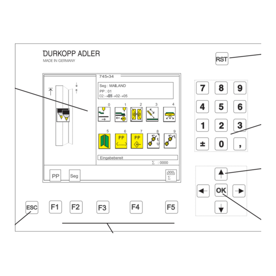
Operating terminal Data input and output is done via an operating terminal with a colour LCD display and a multipurpose keyboard. RST (reset) Colour display Decimal keypad Cursor keys OK key ESC key Function keys Key/key group Function Function keys Call sewing-program parameter screens (from the main screen). -
Page 9: Selecting The Language
Selecting the language – Switch on the main switch and keep pressing the “ñ” key or – Press the keys “RST” and “ñ” in order to activate the language selection – The different languages are memorized in the control. – By pressing the cursor keys “ñ“... -
Page 10: Memory Dongle
Data transfer can be started by pressing the “F5” key and stopped with the “ESC” key. – If no data dongle 745-34-2 is indicated but e. g. Boot 745-34-2, the dongle will first be formatted after pressing the “F5” key before the data are saved on the dongle. - Page 11 – The dongle is formatted – The data is saved onto the dongle...
-
Page 12: Main Operating Screen
Main operating screen Sewing and test programs: menu structure The user interface exclusively employs internationally intelligible symbols. In addition each function is briefly explained in an information line. The individual parameters and setting and test programs are arranged in various groups. Turn on main switch Main screen... -
Page 13: Changing Parameter Values
Changing parameter values Parameter values are changed in the individual parameter screens. – Select the required parameter with the “ï” or “ð” cursor keys. A black background appears behind the symbol of the selected parameter. – Press the OK key. The settings window appears with the current values or to enable values to be entered. -
Page 14: Sewing Programs
Sewing programs With Class 745-34-2 you can program up to 99 different sewing programs. The individual sewing programs (pocket programs) are freely programmable. 20 independent pocket sequences are available. Each pocket sequence can be composed of a maximum of 8 pocket programs in any order. -
Page 15: Running A Machine Program
6.2 Running a machine program – Turn on the main switch. The controller is initialized. – The Dürkopp Adler Logo briefly appears in the display. – The controller checks the position of the transport carriage. The following display appears: Info line: Reference run –... -
Page 16: Main Screen
6.3 Main screen The main screen displays the seam pattern, sewing program, selected pocket sequence and important parameters. Parameters can be individually selected by the user. Info line Seam pattern The left half of the display shows the seam pattern of the selected pocket program. - Page 17 Parameters The symbols in the center of the right half of the display give rapid access to important parameters. Up to ten parameters can be selected by the operator for display on the main screen (see also section 6.7). Parameters can be changed directly on the decimal keypad. The number of the key to be pressed is displayed to the right of the parameter symbol.
-
Page 18: Pocket Programs
Pocket programs ( This menu item contains the parameters for programming the various pocket programs. They are used to program the seam and its associated additional functions. Info line: Select pocket program – While the main screen is displayed press function key F1. The display switches to the pocket-program screen. - Page 19 Programming the seam pattern The actual pocket form is programmed under this menu item. The programmed pocket is shown with the corresponding information in the left half of the display. The corresponding parameter symbols appear in the right half. – Select the required parameter with cursor keys “ï”, “ð”, “ñ”...
- Page 20 Seam-start pattern This parameter selects the form of the seam pattern at the seam start. Straight seam pattern Slanting seam pattern (left) Slanting seam pattern (right) – Select the required seam form with cursor keys “ï”or “ð”. – Press the “OK” key. The seam-angle entry window appears: Seam angle Entry: 01 …...
- Page 21 Seam-end pattern This parameter selects the form of the seam pattern at the seam end. Straight seam pattern Slanting seam pattern (left) Slanting seam pattern (right) – Select the required seam form with cursor keys “ï”or “ð”. – Press the “OK” key. The seam-angle entry window appears: Seam angle Entry: 01 …...
- Page 22 Select flap side The sewing length is equipped with a reflecting light barrier for the recognition of the seam start and end when sewing with flaps. The parameter indicates which side the flap is attached. When the parameter is changed the flap side of the seam pattern automatically switches in the display.
- Page 23 Seam-end mode left/ right needle Four different seam locks are available for the seam end. They can be set separately for the right and left needles. Single bartack Stitch compaction Number of bartack stitches Entry: 01 … 05 [stitches] In zip-fastener mode the bartack length at the seam end is limited to a maximum of 3 mm.
- Page 24 Selecting the positioning point Depending on the type of piece being sewn, positioning takes place at the rear, center or front positioning point. Rear positioning point (with respect to the operator) Center positioning point Front positioning point (with respect to the machine) head) Distance from the center positioning point to the rear positioning point...
- Page 25 Light-barrier adjustment This parameter is used to adjust the light barrier for the seam start and seam end. Seam-start adjustment Seam-end adjustment Entry: -20.0 … + 20.0 mm Selecting laser markings A maximum of 16 lasers can be assigned to each pocket program. With the number keys 1 to 8 on the numerical display the respective laser (1-8) can be switched on (with asterisk) or off (no asterisk).
- Page 26 Sewing head This parameter is used to change values affecting the sewing head. Sewing speed Entry: 2000 … 3000 [rpm] Soft start Entry: on/off Soft-start speed Entry: 0500 … 900 [rpm] Number of soft-start stitches Entry: 01 … 20 [stitches] Reselect icon Thread-clamp release stitches Entry: 01 - 99...
- Page 27 Center blade Center blade Entry: on/off CAUTION: Switching off the center blade automatically switches off the corner blades too. However, switching the center blade back on does not automatically switch the corner blades back on again. They must be switched on separately. Center-blade rpm Entry: 1700...3000 [rpm] Select with the “ñ”...
- Page 28 Corner blades Manual corner-blade station Switching corner blades on/off Entry: on/off Info line: Corner blades on/off All four corner blades on/off Left corner-blade incision at seam start on/off Right corner-blade incision at seam start on/off Left corner-blade incision at seam end on/off Right corner-blade incision at seam start on/off...
- Page 29 Automatic corner-blade station Switching corner blades on/off Entry: on/off Info line: Corner blades on/off All four corner-blades on/off Left corner-blade incision at seam start on/off Right corner-blade incision at seam start on/off Left corner-blade incision at seam end on/off Right corner-blade incision at seam end on/off...
- Page 30 Adjusting the left-corner-blade incision at the seam start Changing this value carries out the fine adjustment of the left-corner-blade incision at the seam start. Entry: - 20.0 … + 20.0 0 = no adjustment + = corner-blade position sooner - = corner-blade position later Adjusting the right-corner-blade incision at the seam start...
- Page 31 Tape feed Switching the tape feed on/off Entry: on/off Seam-start tape-length Entry: 00.0 … 99.9 mm Seam-end tape-length Entry: 00.0 … 99.9 mm Flap sequence No flap clamps Close left flap clamp first, then right Close right flap clamp first, then left Close both flap clamps simultaneously Only right flap clamp present Only left flap clamp present...
- Page 32 Transport-carriage settings Info line: Return velocity Return velocity (after sewing) The return velocity from the needles to the insertion station can be reduced. Entry: 010 … 100 %] Even if work is interrupted the carriage moves backwards at the same velocity. Slide-in velocity The slide-in velocity from the insertion station to the needle and corner station can be reduced.
- Page 33 No material feed after corner incision Material feed/ Stacker position After the corner incision the feed clamps transport the material to the set position. Entry: 001 - 100 [mm] Hint: The smaller the entry, the further the carriage moves to the rear. = rear position = cutting position Carriage return with material feed...
- Page 34 Switching the flap feed on/off (versions B and F only) Entry: on/off Mode 1 Flap feeders swivel out. Mode 2 Flap feeders remain swivelled in. Sewing patterned or plain material (versions “D” and “F” only) Patterned material Plain material Switching the piping blade on/off (versions B and F only) Entry: on/off Cutting depth at the seam beginning...
- Page 35 Breast-welt mode Entry: on/off Rapid clamp adjustment Info line: Rapid clamp adjustment Rapid clamp adjustment Clamp left outer, right outer Clamp left outer, right inner Clamp left inner, right outer Clamp left inner, right inner CAUTION: danger of breakage If the single-piping folder is fitted do not select a double-piping program, i.e.
- Page 36 Feed-clamp sequence right/left Both clamps descend simultaneously Lower left clamp first Lower right clamp first Entering the program name This parameter assigns a name to any pocket program. The program name is limited to 18 letters. – Select the parameter with cursor keys “ð” or “ï”. –...
- Page 37 Switching the zip-fastener scissors on/off Entry: on/off Initializing program memory The program loads a standardized factory setting, including seam pattern, for the sewing-program parameters. – Press function key F3. “Initialize sewing program?” appears in the display. – Press function key F5. The parameters are restored to the factory settings.
-
Page 38: Blower Mode
Blower mode Entry: 0, 1, 2, 3, 4. 5. 6, 7 Valve YC108 Valve YC109 Application Position blowing on blowing off Position blowing on blowing off Mode 0 active active function off Mode 1 blower pipe flap clamps needles on blower pipe needles on folding sheet needles on... - Page 39 Notes:...
-
Page 40: Pocket Sequence
Pocket sequence ( This menu item is used to assemble individual pocket programs into callable sequences. A total of 20 independent pocket sequences are available. Each pocket sequence can consist of up to 8 pocket programs in any order. Info line: Sequence programming Programming a pocket sequence –... - Page 41 Entering a sequence name – While the sequence screen is displayed press function key “F2”. The display switches to the sequence-name screen. Info line: Entering sequence name – Press function key “F2” or “F3” to enter the first letter. – Press the “ð”...
-
Page 42: Setting And Test Programs
Setting and test programs The machine software includes various machine-specific setting and test programs, together with the well-known MULTITEST system. A terminal self-test checks the individual components of the operating terminal. Calling setting and test programs Once the machine has been switched on, pressing certain keys opens the various groups of setting and test programs. - Page 43 – The key for the required setting or test program should be pressed and held down. – Turn on the main switch. The controller is initialized. The DÜRKOPP-ADLER logo briefly appears in the display. The display switches to the corresponding group of setting and test programs.
-
Page 44: Machine Parameters
Machine parameters ( or main switch on + The machine parameters describe the machine’s technical configuration as well as its settings and their adjustment values. CAUTION: Changes to machine settings usually entail mechanical conversion. For this reason this program section is only accessible after the entry of code number “25483”. - Page 45 Corner-blade settings for angles This parameter tells the controller whether the corner blades are to be set manually or automatically. Manual corner-blade positioning Automatic corner-blade positioning Maximum sewing length Entry: 180, 200, 200 , 220 [mm] Select with the “ò” or “ñ” keys. Folder unit Entry: A, B, D, F...
- Page 46 Selecting the flap feed mode (versions B and F only) Info line: without flap feed without Flap Feed Flap Feed switched off Flap Feed Mode 1 Step forward on the right pedal, left flap feed opens. Step back on the right pedal, right flap feed opens.
- Page 47 without Tape Feed Tape feeding switched off Tape Feed with Step Motor Equipment: electromotor driven tape feeder Electro-pneumatic Tape Feeding Equipment: electro-pneumatic driven tape feeder Switching the vacuum system on/off This parameter tells the controller whether the machine is fitted with a vacuum system.
- Page 48 Switch waistband clamp on/off This parameter signalizes the control whether the sewing unit is equipped with a waistband clamp or not. Pocket bag over flap mode Any change concerning the pocket bag over flap mode should be done here i.e. in which position the raised feed clamp goes for the inserting position.
- Page 49 Activating the smoother This parameter tells the controller whether the machine is fitted with a smoother. The smoother is switched on and off in the pocket-program menu item (F1) on the main screen. Entry: on/off Selecting light barriers for flap scanning Info line: distance measurement…...
-
Page 50: Machine-Specific Setting And Test Programs
7.3 Machine-specific setting and test programs or main switch on + The machine-specific test programs test and adjust individual machine components. Info line: Adjusting the looper-thread monitor – Press the “RST” key or turn the main switch on and press function key “F2”. -
Page 51: Adjusting The Looper-Thread Monitor
7.3.1 Adjusting the looper-thread monitor This program aligns the reflecting light barriers of the looper-thread monitor. Info line: Adjusting the looper-thread monitor – Press OK to run the test program. Two looper-thread bobbins and the light-barrier reflecting heads appear in the display. When the light barriers are correctly aligned a reflection occurs when an empty bobbin turns. -
Page 52: Initializing Memory
7.3.2 Initializing memory The program loads a standardized factory setting for the sewing-program parameters, e.g. for a new controller: Info line: Initializing memory CAUTION: Once one of these three programs has been run the parameters set are overwritten with a standardized factory setting. For this reason this program section can only be run after the entry of code number “25483”. -
Page 53: Checking The Smoother Function
– Select the required test program with cursor keys “ï” or “ð”. A black background appears behind the symbol. – Press OK to run the selected program. – To leave machine parameters press the “RST” key or turn off the main switch. -
Page 54: Aligning The Light Barriers
7.3.4 Aligning the light barriers This program aligns the reflecting light barriers for recognition of the seam start and end. First light barrier Second light barrier for flap scanning Info line: Aligning the light barriers The light barriers are adjusted with two templates. Left template = for straight pockets. -
Page 55: Preparing The Sewing Unit And Feed Clamps
7.3.4.1 Preparing the sewing unit and feed clamps Caution: danger of injury The light barriers are adjusted with the machine switched on. The utmost care must be taken when carrying out adjustments and function-testing. CAUTION: danger of breakage It is essential for the folder station to be swivelled out for the light barriers to be adjusted. -
Page 56: Service Instructions
Check of the light barrier position with swung-in folder – When the feeding clamps are in the rear position, swing the folding station 1 in. – Press key “7“. Folder (A) or pick-up folder (B/F) are made pressureless. – Press the folder on the sliding sheet manually and pull the feeding clamps to the front. -
Page 57: Sewing Unit With Two Light Barriers For Automatic Angle Recognition
7.3.4.2 Sewing unit with two light barriers for automatic angle recognition Caution: danger of injury During the reference run the feed clamps move forwards or back and forth several times. Do not reach into the path of the feed clamps. Folding station must be swung out –... - Page 58 Caution: danger of injury During template scanning the feed clamps move back and forth several times. Do not reach into the path of the feed clamps. – Press function key “F5”. The straight-pocket template is scanned. The scanned parameters appear in the display. They are automatically passed to the controller.
-
Page 59: Sewing Unit With Two Light Barriers, Left Or Right Flap Positioning
7.3.4.3 Sewing unit with two light barriers, left or right flap positioning Caution: danger of injury During the reference run the feed clamps move forwards or back and forth several times. Do not reach into the path of the feed clamps. Folding station must be swung out –... - Page 60 Caution: danger of injury During template scanning the feed clamps move back and forth several times. Do not reach into the path of the feed clamps. Folding station must be swung out – Press function key “F5”. The template is scanned. The scanned parameters appear in the display.
-
Page 61: Sewing Unit With One Light Barrier
7.3.4.4 Sewing unit with one light barrier Caution: danger of injury During the reference run the feed clamps move forwards or back and forth several times. Do not reach into the path of the feed clamps. Folding station must be swung out –... -
Page 62: Error Display
Caution: danger of injury During template scanning the feed clamps move back and forth several times. Do not reach into the path of the feed clamps. Folding station must be swung out – Press function key “F5”. The template is scanned. The scanned parameters appear in the display. -
Page 63: Checking The Corner-Blade Settings
7.3.5 Checking the corner-blade settings This program checks the corner-blade distances. Info line: Adjusting corner blades – Select the required parameter with cursor keys “ï” or “ð” . A black background appears behind the symbol. – Press OK to run the selected program. Corner-blade machine parameters Corner-blade distance Seam-start corner-blade adjustment... -
Page 64: Checking The Corner-Blade Station
7.3.5.1 Checking the corner-blade station Caution: danger of injury Serious cuts may result from reaching into the vicinity of the corner blades. The utmost care must be taken when carrying out tests on the machine when it is running. – Press function key “F3”. -
Page 65: Checking Corner-Blade Motion
7.3.5.4 Checking corner-blade motion Caution: danger of injury Do not reach into the vicinity of the corner blades. When rising they can inflict serious cuts. The utmost care must be taken when testing the corner blades when the machine is in operation. The individual corner blades are tested in sequence. -
Page 66: Corner-Blade Machine Parameters
7.3.5.5 Corner-blade machine parameters Basic positioning of the corner blades to the seam is carried out in the machine-parameter program. – Select “corner-blade machine parameters ” with cursor keys “ï” or “ð”. A black background appears behind the symbol. – Press OK to start the program. - Page 67 Seam-end corner-blade correction value Entry: -99.9 … 99.9 Seam-start corner-blade correction value Entry: -99.9 … 99.9 Hint: The value entered is valid for all pocket programs. If the seam-end value is changed, the seam-start value is automatically corrected. Distance from the center-blade incision to the seam ends (x) (see the illustration at the foot of page 62) Entry: - 99.9 …...
-
Page 68: Testing Needle And Center-Blade Activation
7.3.6 Testing needle and center-blade activation This program tests the activation of the needles and the center blade with the machine running. Info line: Activating needle, center blade – Press OK to start the program. – Press function key F3: once to start the sewing drive at 1000 rpm, a second time to increase the sewing-drive speed to 3000 rpm and a third time to stop in position 2 (thread lever up) -
Page 69: Checking The Tape Feed
7.3.7 Checking the tape feed This program tests the feed and trimming function of the tape feed Info line: Checking tape feed – Press OK to run the test program. – Press function key F4. The tape feed starts. The tape is fed and the brake released. key is blocked. -
Page 70: Checking The Gripper Folder Without Feed Clamp (Versions B And F Only)
7.3.8 Checking the gripper folder without feed clamp (versions B and F only) This program tests the function of the gripper folder. The feed clamps remain in their rear end position. Info line: Testing gripper folder – Press OK to run the test program. –... -
Page 71: Checking The Insertion Process With Feed Clamp
7.3.9 Checking the insertion process with feed clamp This program tests the insertion process. Info line: Testing insertion process – Press OK to run the test program. A reference run must be executed. The following appears in the display: – Push the left pedal down. -
Page 72: Checking And Adjusting The Piping Knives
7.3.10. Checking and adjusting the piping knives In the test program “Checking and adjusting the piping knives” you can check the knife and step motor motion and adjust the reference position of the piping knives. – Press key “F3“ : Make reference run. -
Page 73: Setting The Piping Knife Reference Position
7.3.10.2 Setting the piping knife reference position – Select the symbol with the cursor keys “ï” and “ð” – Start the program with the “OK” key. The display shows the input prompt for the code number. Code Enter the code number “25483" via the numeric keyboard. The screen menu for the piping knife reference position appears. -
Page 74: Step-By-Step Mode
7.3.11 Step-by-step mode In the step-by-step mode the sewing cycle is halted at important positions so that individual processes can be checked. – Press OK to run the test program. The main screen appears with a reminder to execute a reference run. -
Page 75: Determining The Cycle Time
7.3.12 Determining the cycle time This program determines the machine’s cycle time. – Press OK to run the test program. The cycle time appears on the main screen. Info line: Cycle time Reference run – Execute a reference run. – When the set sewing program has been completed the cycle time appears in the display. -
Page 76: Multitest System
7.4 MULTITEST system ( or main switch on + The MULTITEST system programs enable input and output elements to be tested quickly. No additional instruments are required. – Press and hold down key “F3”. – Press the “RST” key. The controller is re-initialized and the MULTITEST system screen is loaded. -
Page 77: Displaying The Program Version And Checksum
7.4.1 Displaying the program version and checksum This program tests the microcomputer’s read-only memory (ROM). Program version Where program versions are of the same class and have the same code letter the higher version replaces all lower versions. Checksum The checksum is only intended for factory servicing. It enables our specialists to establish whether the controller’s program memory (EPROM) contains the whole program with no errors. -
Page 78: Testing Ram
7.4.2 Testing RAM (Random-Access Memory) This program tests the microcomputer’s working memory (RAM). – Press OK to run the test program. The test result appears in the display. Display Explanation RAM OK random-access memory is operating perfectly RAM ERROR error in random-access memory Hint: If the message RAM ERROR occurs during the RAM test, the control must be replaced. -
Page 79: Selecting Input Elements
7.4.3 Selecting input elements This program adjusts the input elements. CAUTION: The input elements are factory-set with great care. Adjustment and correction may only be undertaken by trained service personnel. – Press OK to run the test program. – Use the key to select between the basic module and the CAN node. - Page 80 Input elements DACIII Input Function Insertion method element Needle-thread monitor left Needle-thread monitor right Folder down Folding station swung in Simple piping right Simple piping left Knife bracket monitoring Remove material/ cover monitoring Pressure monitor Right pedal forward Left pedal forward Left pedal back Right pedal back Flap scanning 1...
-
Page 81: Checking Input Elements
7.4.4 Checking input elements This program tests automatically the input elements. – Press OK to run the test program. – Select the input element to be tested. – The display shows the circuit diagram designation and the switching status of the input element selected (e.g. “+s17”). The display changes if the switching status is altered or another input element is changed. -
Page 82: Selecting Output Elements
7.4.5 Selecting output elements This program checks the function of the output elements. One (single mode) or several (multi-mode) output elements can be tested simultaneously. Caution: danger of injury ! Do not reach into the machine while it is running and the function of the output elements is under test. - Page 83 Output elements head unit (DACIII) Output Function Insertion method element Upper thread cutter on/ Close thread clamp Center blade on Blow away fluff/advance thread Open thread clamp Lower thread cutter on Thread tension on Needle left on Needle right on Output elements transport unit (DACIII) Output Function...
- Page 84 Output Function Insertion method element YC119 Close tape cutter YC120 Pull tape to the front YC121 Loosen tape YC122 Zip-fastener scissors forward Piping knife forward YC123 Open zip-fastener scissors Piping knife forward Swivel positioning device YC124 Lift stop motion device Swivel positioning device YC125 Drive out waistband-clamp needles...
-
Page 85: Can Test
7.4.6 CAN test Press “OK” to run the test program. Hint: Displaying the OK message takes some considerable time. CAN modules work with no errors. -
Page 86: Checking The Sewing Drive
7.4.7 Checking the sewing drive This program tests the needle position and the various speed stages of the sewing drive. – Press OK to run the test program. – Select the required parameter with cursor keys “ï” or “ð”. A black background appears behind the symbol. –... -
Page 87: Error List
Set sewing-drive speed minimum = 70 rpm maximum = 3000 rpm Checking the sewing drive key F2 = start key F3 = stop – To leave the test program press function key F1. 7.4.8 Error list The program shows the 10 last error messages. –... -
Page 88: Terminal Self-Test
7.5 Terminal self-test ( or turn on main switch + Service personnel use the terminal self-test to check the individual components of the operating terminal. – RAM test The RAM test checks the operating terminal’s working memory (“video RAM”). On completion of the RAM test the self-test automatically switches to the EPROM test. -
Page 89: Display Contrast Value
7.6 Display contrast value ( or turn on main switch + This program sets the contrast value of the display. – Set the contrast value with cursor keys “ñ” or “ò”. – Press the “ESC” key to store the value and leave the program. -
Page 90: Editing Menus
7.7 Editing menus ( or turn on main switch + This determines which parameters can be directly edited on the main screen with keys 0 to 9. – Pressing function key F5 switches to the next screen with other parameters. –... -
Page 91: Adjusting The Serial Interface
7.8 Adjusting the serial interface ( This test program sets the correct transfer speed (baud rate) for the serial interface. The correct baud rate for the serial interface is: Com 0 = n, 8, WA, 1 - 125 K Baud CAUTION: If the machine is switched on with one of the following keys pressed, baud rates incompatible with the operating panel of the controller will... -
Page 92: Error Messages
Error messages In the event of an error in the control system or the machine program the error number appears in the display. The following tables will enable the cause of the error to be identified and remedied. 8.1 Sewing motor controller error messages Error number Meaning Remedy... -
Page 93: Stepping Motor Error Messages
8.2 Stepping motors error messages Error number Meaning Remedy Error 2101 Step motor feed clamp timeout reference - Faulty cable to the reference switch - Replace cable - Faulty reference switch - Replace reference switch Error 2103 Step motor feed clamp has step loss - Check seizing of the feed clamp Error 2152 Step motor feed clamp excess... - Page 94 Error number Meaning Remedy Error 3121 Insufficient or missing compressed Increase the flow or stabilize the air air pressure pressure Error 3210 Thread breakage Re-thread the machine again Error 3220 Empty bobbin Insert full bobbin Error 3500 Error Command Interpreter / - Switch the machine off/on again 3507 Motor synchronization...
- Page 95 Error number Meaning Remedy Error 7556 Communication Control Panel 7557 interface - Interference - Switch off the source of interference - Faulty control panel interface cable - Replace the cable Error 8151 IDMA error 8156 - Failure - Switch the machine off/on again - Faulty control - Replace the control 8159...
- Page 96 Error number Meaning Remedy Info 9000 Reminder to execute the reference Push left pedal backwards run after switching on Info 9001 Corner-blade station is swivelled out Swivel corner-blade station in Error 9001 Corner-blade station swivelled out Check/adjust the fastening of the during sewing.
- Page 97 Error number Meaning Remedy Info 9720 Error at the light barrier for flap Check the reflecting foil; Check the scanning alignment of the light barriers Info 9721 Flap has been positioned in front of Position the flap correctly the front positioning point Info 9722 Flap protrudes from the maximum...
Need help?
Do you have a question about the 745-34-2 and is the answer not in the manual?
Questions and answers