
Subscribe to Our Youtube Channel
Related Manuals for Power Acoustik PL-10A


Summary of Contents for Power Acoustik PL-10A
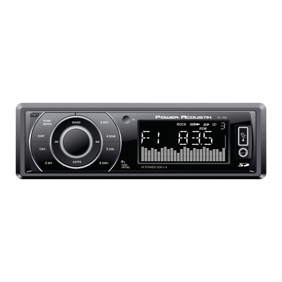
- Page 1 OWNER’S MANUAL Mobile Audio System PL-10A PLL Synthesizer Stereo Radio Automatic Memory Storing Full Detachable Panel Preset Equalization USB Interface SD/MMC Interface...
-
Page 2: Table Of Contents
CONTENTS Installation ........... 3 SD/MMC operation ........ 10 Take out screw before installation ..3 Remote control ........11 DIN Front-Mount (Method A) ....3 Specification ......... 12 Trouble shooting ........13 Installing the unit ....... 3 Removing the unit ......4 DIN Rear-Mount (Method B) .... -
Page 3: Installation
INSTALLATION Notes: DIN FRONT-MOUNT (Method A) Choose the mounting location where Installation Opening the unit will not interfere with the This unit can be installed in any dashboard normal driving function of the driver. having an opening as shown below: Before finally installing the unit, connect ... -
Page 4: Removing The Unit
INSTALLATION 6. Mount the sleeve by inserting the sleeve terminal to the dashboard. into the opening of the dashboard and Hex Nut Spring Washer bend open the tabs located around the Metal Strap sleeve with a screwdriver. Not all tabs Mounting Bolt will be able to make contact, so Plain Washer... - Page 5 INSTALLATION asten the unit to the factory radio mounting brackets supplied with your vehicle. Side View showing Screw Holes marked T, N Screw Factory Radio Mounting Bracket Screw Dashboard or Console To fasten the unit to the factory radio mounting brackets. Align the screw holes on the bracket with the screw holes on the unit, and then tighten the screws (5x5mm) on each side.
-
Page 6: Using The Detachable Front Panel
USING THE DETACHABLE FRONT PANEL REMOVING THE FRONT PANEL Precautions when handling 1. Press the release button ( ) on the 1. Do not drop the front panel. front panel and pull off the front panel. 2. Do not put pressure on the display or control buttons when removing or installing the front panel. -
Page 7: Wiring Connection
WIRING CONNECTION ISO CONNECTION... -
Page 8: Operation
OPERATION LOCATION OF KEYS 1. “ ” button. 13. “ ” button 2. “POW/ MODE” button. 14. “AS/PS” button. 3. “DISP” button. 15. “VOL / SEL/ENT” button. 4. “BAND” button. 16. “ ” button. 5. “4 RDM” button. 17. “2 INT ” button. 6. -
Page 9: Switching On/Off The Unit
OPERATION SWITCHING ON/OFF THE UNIT AUXILIARY INPUT Press PWR button (2) to turn on the unit. The unit can be connected to a portable When the unit is on. Press and hold for 2 seconds to turn off the unit. audio player through the AUX IN jack (9). -
Page 10: Sd/Mmc Operation
OPERATION AUTOMATIC MEMORY STORING & Press 5 DIR-button (11) or 6 DIR+ button PROGRAM SCANNING (12) to select previous directory or next - Automatic memory storing directory. Press AS/PS button (14) for several seconds, the radio searches from the PAUSING PLAYING current frequency and checks the Press 1... -
Page 11: Remote Control
REMOTE CONTROL HANDSET(OPTIONAL) FUNCTION KEY & CONTROL 1. POWER Power ON/OFF Button 2. MODE Mode Botton(S,T,U,7,For MP3/WMA Operation) 3. TUNE/SKIP Tune/SKIP Down Button(V,W,X,8 For MP3/WMA Operation) 4. 7/BND Band Select Button(When pressed shortly) 5. SCN Scanning Button(D,E,F,2 For MP3/WMA Operation) 6. -
Page 12: Specification
SPECIFICATION GENERAL Power Supply Requirements : DC 12 Volts, Negative Ground Chassis Dimensions : 178 (W) x 97 (D) x 50 (H) Tone Controls Bass (at 100 Hz) : ±10 dB Treble (at 10 kHz) : ±10 dB Maximum Output Power Version V : 4x40watts Current Drain... -
Page 13: Trouble Shooting
TROUBLE SHOOTING Before going through the checklist, check wiring connection. If any of the problems persist after checklist has been made, consult your nearest service dealer. Symptom Cause Solution The car ignition switch is power supply No power. not on. connected to the car accessory circuits, but the engine is not moving, switch the ignition key...
Need help?
Do you have a question about the PL-10A and is the answer not in the manual?
Questions and answers