Table of Contents
Advertisement
Quick Links
Download this manual
See also:
Service Manual
Advertisement
Table of Contents

Subscribe to Our Youtube Channel
Related Manuals for Icom IC-M32


Summary of Contents for Icom IC-M32
-
Page 1: Instruction Manual
INSTRUCTION MANUAL VHF MARINE TRANSCEIVER iM32 This device complies with Part 15 of the FCC Rules. Operation is subject to the condition that this device does not cause harmful inter- ference. -
Page 2: Safety Training Information
• ALWAYS keep the antenna at least 2.5 cm (1 inch) away from the body such levels for exposure to humans: when transmitting and only use the Icom belt-clips which are listed on • FCC OET Bulletin 65 Edition 97-01 Supplement C, Evaluating Compli- page 32 when attaching the radio to your belt, etc., to ensure FCC RF... -
Page 3: In Case Of Emergency
IN CASE OF EMERGENCY RECOMMENDATION If your vessel requires assistance, contact other vessels and CLEAN THE TRANSCEIVER THOROUGHLY WITH FRESH WATER after exposure to saltwater, and dry it before opera- the Coast Guard by sending a distress call on Channel 16. tion. -
Page 4: Foreword
FOREWORD FEATURES ☞ Waterproof construction Thank you for purchasing this Icom product. The IC-M32 VHF MARINE TRANSCEIVER is designed and built with Icom’s Built tough to withstand the punishing marine environ- state of the art technology and craftsmanship. With proper care ment, the transceiver’s submersible construction meets... -
Page 5: Precaution
FCC regulations. from your vessel’s magnetic navigation compass. Icom, Icom Inc. and the Icom logo are registered trademarks of Icom Incor- porated (Japan) in the United States, the United Kingdom, Germany, France, Spain, Russia and/or other countries. -
Page 6: Table Of Contents
TABLE OF CONTENTS SAFETY TRAINING INFORMATION ........i 5 SCAN OPERATION ����������������������������������������������� 14–15 IN CASE OF EMERGENCY ..........ii ■ Scan types ..............14 RECOMMENDATION ............ii ■ Setting tag channels ..........15 FOREWORD ..............iii ■ Starting a scan ............15 IMPORTANT .............. -
Page 7: Operating Rules
(1) SHIP STATION LICENSE When your craft is equipped with a VHF FM transceiver, you NOTE: Even though the IC-M32 is capable of operation must have a current radio station license before using the on VHF marine channels 3, 21, 23, 61, 64, 81, 82 and transceiver. -
Page 8: Supplied Accessories And Attachments
SUPPLIED ACCESSORIES AND ATTACHMENTS ■ Supplied accessories D Handstrap Pass the handstrap through the loop on the side of the The following accessories are supplied: Qty. transceiver as illustrated at • Flexible antenna ....... . 1 right. -
Page 9: Supplied Accessories And Attachments
CAUTION: To attach the battery pack: When attaching or removing a battery pack, make sure Insert the battery pack in the IC-M32 completely, then turn the rubber seal is set in the groove of the battery pack the screw clockwise. -
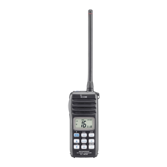
Page 10: Panel Description
PANEL DESCRIPTION ■ Front, top and side panels q POWER SWITCH [PWR] Push and hold to turn power ON and OFF. w ANTENNA CONNECTOR (p. 2) Connects the supplied antenna. e SCAN/DUAL KEY [SCN• DUAL • Starts and stops normal or priority scan. (p. 15) Speaker •... - Page 11 PANEL DESCRIPTION u CHANNEL UP/DOWN KEYS [Y]/[Z]• o CHANNEL 16 KEY [16•9] [TAG] • Selects an operating channel. (pgs. 8, 9) • Selects Channel 16 when pushed. (p. 8) • Selects the SET mode condition of the item. (p. 17) •...
-
Page 12: Function Display
PANEL DESCRIPTION ■ Function display t LOCK INDICATOR (p. 13) Appears while the lock function is activated. y BATTERY INDICATOR Indicates remaining battery power. Indication Charging Battery level Full Middle No battery required blinks when the battery over charged. blinks when the battery is exhaustion. u SCAN INDICATOR (p. -
Page 13: Panel Description
PANEL DESCRIPTION !1 SQUELCH LEVEL INDICATOR !8 LOW POWER INDICATOR (p. 11) Shows the squelch level. • “LOW” appears when low power is selected. • “LOW” blinks when switching forced low power mode !2 VOLUME LEVEL INDICATOR because of a high temperature error or low voltage. Shows the volume level. -
Page 14: Basic Operation
BASIC OPERATION ■ Channel selection D Channel 9 (Call channel) IMPORTANT: Prior to using the transceiver for the first time, the battery pack must be fully charged for optimum Channel 9 is the leisure-use call channel. Each regular chan- life and operation. To avoid damage to the transceiver, nel group has separate call channels. -
Page 15: Weather Channels
U/I/C ✔ CONVENIENT! U.S.A. channels The IC-M32 can detect a weather alert tone on the selected weather channel while in another channel (when the power save function is turned ON) or during scanning. See the “SET mode items” on p. 18 for details. -
Page 16: Adjusting The Volume Level
■ Adjusting the squelch level The volume level can be adjusted with [+]/[–]. The IC-M32 has a squelch level adjustment, even though there is no control knob for it. In order to receive signals properly, as ➥ Push [+]/[–] to adjust the volume level. -
Page 17: Receiving And Transmitting
MONI For U.S.A version: To prevent accidental prolonged level. transmission, etc., the IC-M32 has a time-out timer func- e Push [Y]/[Z] to select the desired channel. tion. This timer cuts a transmission OFF after 5 min. of - When receiving a signal, “... -
Page 18: Call Channel Programming
BASIC OPERATION ■ Call channel programming t Push [16 ] to program the dis- The call channel key is used to select Channel 9 by default, •9 however, you can program your most often-used channel in played channel as the call chan- nel. -
Page 19: Lock Function
BASIC OPERATION ■ Lock function ■ Monitor function This function electronically locks all keys (except for [+]/[–], The monitor function releases the noise squelch mute. See [PTT], [SQL• ] and [H/L ]) to prevent accidental p. 19 for details of the monitor switch action. MONI •LOCK channel changes and function access. -
Page 20: Scan Operation
SCAN OPERATION ■ Scan types Set the tag channels (scanned channel) before scanning. Scanning is an efficient way to locate signals quickly over a wide frequency range. The transceiver has priority scan and Clear the tag channels which inconveniently stop scanning, such as digital communications. -
Page 21: Setting Tag Channels
SCAN OPERATION ■ Setting tag channels ■ Starting a scan For more efficient scanning, add desired channels as tag Set the weather alert function, priority scan function, scan channels or clear the tag for unwanted channels. resume timer and auto scan function in advance, using SET Non-tag channels will be skipped during scanning. -
Page 22: Dualwatch/Tri-Watch
DUALWATCH/TRI-WATCH ■ Description ■ Operation Dualwatch monitors Channel 16 while you are receiving q Select the desired operating channel. another channel; tri-watch monitors Channel 16 and the call w Push [SCN ] for 1 sec. to start dualwatch or tri-watch •DUAL channel while receiving another channel. -
Page 23: Set Mode
SET MODE ■ SET mode programming D SET mode operation SET mode is used to change the condition of 12 transceiver functions: Beep tone function, Weather alert function, Prior- q Turn power OFF. ity scan function, Scan resume timer, Auto scan function, w While pushing [SQL•... -
Page 24: Set Mode Items
SET MODE ■ SET mode items D Weather alert function “AL” D Beep tone function “bP” An NOAA broadcast station transmits a weather alert tone You can select silent operation by turning the beep tones OFF, or you can have 2 types of confirmation beeps sound before any important weather announcements. - Page 25 SET MODE D Scan resume timer “St” D Dual/Tri-watch function “dt” The scan resume timer can be set as a pause (OFF) or timer This item selects dual or tri-watch as desired. See p. 16 for scan (ON). When OFF is selected, the scan pauses until a details.
- Page 26 SET MODE D Automatic backlighting “bL” D Power save function “PS” This function is convenient for nighttime operation. The au- The power save function reduces current drain by deactivat- tomatic backlighting turns the backlighting ON when any key ing the receiver circuit for preset intervals. except for [PTT] is pushed.
- Page 27 SET MODE D Self check function “SC” D Battery voltage indicator “bt” The self check function checks transceiver conditions by it- The voltage of the connected battery pack can be turned ON self, and informs you in case a problem is found. The follow- (displayed for 2 sec.) or OFF (non-displayed) after power is ing items are checked after the power is turned ON, then it turned ON.
-
Page 28: Set Mode
SET MODE SET MODE LIST Function Indication Switch Beep tone function "bP" OFF / ON* / US Weather alert function "AL" OFF* / ON Priority scan function "Pr" OFF* / ON Scan resume timer "St" OFF* / ON Auto scan function "AS"... -
Page 29: Battery Charging
BATTERY CHARGING ■ Battery charging ■ Battery caution CAUTION! NEVER insert battery pack/transceiver Please refer to the BC-162 instruction manual when (with the battery pack attached) with wet or soiled into the charging the BP-252 with the BC-162 Li-ion battery pack charger. -
Page 30: Optional Battery Case
BATTERY CHARGING ■ Optional battery case D Charging connections q Attach the BC-150 to a flat surface, such as a desk or cabin, etc., if desired. When using a battery case attached to the transceiver, in- w Connect the AC adapter as shown below. stall 6 ×... -
Page 31: Optional Battery Chargers
BATTERY CHARGING ■ Optional battery chargers D AD-103 installation w Connect the plugs of the BC-119N/121N to the AD-103 q Install the AD-103 desktop charger adapter into the holder space of the BC-119N/121N. desktop charger adapter with the connector, then install the adapter into the charger with the supplied screws. - Page 32 BATTERY CHARGING D Rapid charging with the BC-119N+AD-103 D Rapid charging with the BC-121N+AD-103 The optional BC-119N provides rapid charging of battery The optional BC-121N allows up to 6 battery packs to be packs. The following are additionally required. charged simultaneously. The following are additionally re- •...
-
Page 33: Swivel Belt Clip
SWIVEL BELT CLIP ■ MB-87 contents w Clip the belt clip to a part of your belt and insert the trans- ceiver into the belt clip until the base clip fitting into the groove. Qty. q Belt clip ................1 w Base clip ................ -
Page 34: To Detach
SWIVEL BELT CLIP ■ To detach Turn the transceiver upside down in the direction of the ➥ arrow and pull out from the belt clip. CAUTION: HOLD THE TRANSCEIVER TIGHTLY, WHEN HANGING OR DETACHING THE TRANSCEIVER FROM THE BELT CLIP� Otherwise the transceiver may not be attached to the holder or swivelled properly if the transceiver is acciden- tally dropped and the base clip is scratched or damaged. -
Page 35: Troubleshooting
TROUBLESHOOTING PROBLEM POSSIBLE CAUSE SOLUTION REF� The transceiver does • The battery is exhausted. • Recharge the battery pack. p. 23 not turn ON. • Bad connection to the battery pack. • Check the connection to the transceiver. p. 3 No sound from speaker. -
Page 36: Vhf Marine Channel List
VHF MARINE CHANNEL LIST Channel number Frequency (MHz) Channel number Frequency (MHz) Channel number Frequency (MHz) Channel number Frequency (MHz) CAN Transmit Receive CAN Transmit Receive CAN Transmit Receive CAN Transmit Receive 156.050 160.650 157.275 161.875 19A 156.950 156.950 156.325 160.925 20 * 157.000 161.600 66A * 157.275 157.275... -
Page 37: Specifications
SPECIFICATIONS D GENERAL D RECEIVER • Frequency coverage : Transmit 156.025–157.425 MHz • Receive system : Double-conversion Receive 156.050–163.275 MHz superheterodyne • Mode : FM (16K0G3E) • Sensitivity (12 dB SINAD) : 0.25 µV typical • Channel spacing : 25 kHz •... -
Page 38: Options
An AC adapter should be purchased sepa- used with this transceiver. We are not responsible for the transceiver rately. being damaged or any accident caused when using non-Icom op- Charging time: approx. 1.5 to 2 hours. tional equipment. - Page 40 A-6297D-1EX-y Printed in Japan 1-1-32 Kamiminami, Hirano-ku, Osaka 547-0003, Japan 2003–2009 Icom Inc. ©...
Need help?
Do you have a question about the IC-M32 and is the answer not in the manual?
Questions and answers
I have a IC-M32 and I broke my antenna, What is the replacement antenna number?
The replacement antenna number for the Icom IC-M32 is FA-SC58V.
This answer is automatically generated