Table of Contents
Advertisement
Quick Links
Advertisement
Table of Contents

Related Manuals for Extech Instruments 380976-K


Summary of Contents for Extech Instruments 380976-K
- Page 1 User Guide 1Φ/3Φ 1000 Amp True RMS Power Clamp-On Model 380976...
-
Page 2: Table Of Contents
Introduction Congratulations on your purchase of the Extech 380976 Power Clamp-On Meter. This device measures 1Φ/3Φ Power (True, Apparent, and Reactive), Horsepower, Phase Angle, True RMS Current/Voltage, Resistance, Capacitance, Frequency, & Temperature. Power measurements can be achieved on 3- or 4-wire configurations. Please read the entire manual to get the most from the meter’s wide array of capabilities. -
Page 3: Warranty
Warranty EXTECH INSTRUMENTS CORPORATION warrants this instrument to be free of defects in parts and workmanship for one year from date of shipment (a six month limited warranty applies to sensors and cables). If it should become necessary to return the instrument for service during or beyond the warranty period, contact the Customer Service Department at (781) 890-7440 ext. -
Page 4: Meter Description
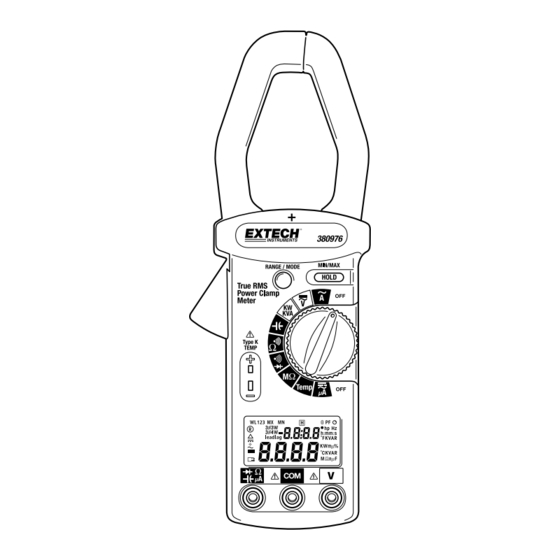
Meter Description Transformer Jaws Jaw opening trigger Data Hold & MX/MN button Function Selector Range button Temperature input jack LCD Display ‘COM’ input jack ‘V’ input jack µA Ω input jack 380976-EU-EN-V3.2 6/12... -
Page 5: Ac + Dc Voltage Measurements
Measurements AC + DC Voltage Measurements WARNING The maximum input is 600V. Do no attempt voltage measurements above this limit. Exceeding this limit could cause electrical shock and damage to the meter. 1. Set the rotary switch to the ‘ V’... -
Page 6: Kw, Kva, Kvar, Power Factor & Phase Angle Measurement
AC Power Measurements 1Φ KW, KVA, KVAR, Power Factor & Phase Angle Measurement 1. Set the rotary switch to the ‘KW/KVA’ position. 2. Insert the test leads to the meter as follows: Black to ‘COM’ and Red to ‘V’. 3. Connect the black lead to the neutral line. 4. -
Page 7: 3-Wire Kw, Hp, Kva, Kvar, Power Factor & Phase Angle Measurement
3Φ 3-Wire KW, HP, KVA, KVAR, Power Factor & Phase Angle Measurement 1. First, measure W (refer to the diagram below). RS(L1L2) Set the rotary switch to the “ V ”. Press and hold the “HOLD” key while setting the rotary switch to “KW/KVA”, the 33W and symbols will appear. - Page 8 3. The power clamp will process these two sets of data (W ), and show the result on the LCD. The W symbol will be shown to indicate 3 3W power. The 3 3W power (in watts) is L123 stored in the meter memory.
- Page 9 NOTE Once a phase is selected as COM, users can not change this selection in the subsequent measurement. For example, if S (or L2) phase is selected, S (or L2) phase is always connected to the COM during measurement of W (or W ) and L1L2...
-
Page 10: 4-Wire Kw, Hp, Kva, Kvar, Power Factor & Phase Angle Measurement
3Φ 4-Wire KW, HP, KVA, KVAR, Power Factor & Phase Angle Measurement 1. First, measure W (refer to the diagram below). R(L1) Set the rotary switch to the “ V ” position. Press and hold the “RANGE” key while setting the rotary switch to the “KW/KVA” position, the 34W and W symbols should appear. - Page 11 3. Third, measure W T(L3) (refer to the diagram that follows the steps below) Disconnect the test probe from the phase where the jaws were clamped in the previous measurement. Connect the test probe of the V (red) terminal to the third phase (e.g. T or L3 phase). Clamp the phase where the test probe is connected to (e.g.
- Page 12 4. The power clamp will process these three sets of data (W ) and show the result on the LCD. The WL symbol will be shown to indicate the 3 4W power (refer to diagram). The 3 4W power value in watts is now stored in the meter’s memory. 5.
-
Page 13: Resistance And Audible Continuity Measurements
KW+KVAR, KVA+ θ (Phase Angle) or A+V displays. 6. W R(L1) S(L2) T(L3) KVAR 7. Set the rotary switch to another position to exit this mode and clear the stored data. NOTE 1. -
Page 14: Capacitance Measurements
Capacitance Measurements 1. Fully discharge the capacitor under test before proceeding. 2. Insert the test leads into the input jacks. (Black to ‘COM’ and Red to ‘ ’). 3. Set the rotary switch to the ‘ ’ position. 4. Connect the red and black test leads to the capacitor. For Electrolytic (polarized) capacitors, connect the red test lead to the positive side and the black lead to the negative side. -
Page 15: Meter Control Keys
Meter Control Keys HOLD - MX/MN Key Data Hold Function Press this key momentarily to put the meter into Data Hold mode (HOLD will appear on the LCD). In this mode, the meter freezes the displayed reading. To exit the Data Hold mode, press the key again (the HOLD icon will switch off). -
Page 16: Automatic Sleep Mode And Battery Replacement
Automatic Sleep Mode and Battery Replacement The Meter is powered by a 9V battery. An AUTO SLEEP feature is included to preserve battery life. Note: The Auto Power OFF feature is disabled when the meter is in the MIN/MAX mode Note: In the sleep mode the meter continues to draw a small amount of battery current. -
Page 17: Specifications
Specifications General Specifications Display Dual Display; 4-digit, 10,000 count (0 to 9999) LCD Jaw Opening 1.6” (42mm) Max. Input limit Max. voltage between any terminal and ground: 600Vrms Sampling rate 2.5 times per second (Digital Display); Once every 6 seconds (KW, KVA, and KVAR) Auto Sleep After approx. - Page 18 Measurement Specifications Accuracy: ± (% of rdg + number of digits) from 18 C to 28 C (64 F to 82 F) R.H. < 80% AC Current (50Hz to 400Hz) True RMS Range Resolution Accuracy (% reading) Sensitivity Overload Protection 99.99A 10mA ±...
- Page 19 M(Resistance) Range Resolution Accuracy Overload Protection 9.999MΩ 1KΩ ±(5% + 10d) 600V 99.99MΩ 10KΩ Capacitance Range Resolution Accuracy Overload Protection 10.000F 10nF ±(1.5% + 5d) 100.00F 600V 100nF 1000.0F ±(4.5% + 15d) 7000F 1F Diode (Continuity <40mV) Range Resolution Accuracy Overload Protection 2.000V ±(2% + 1d)
- Page 20 ±6.0º ACV>100V, ACA>10A Frequency Range Resolution Accuracy Sensitivity 40Hz/1KHz 0.1Hz ±(0.5% + 2d) ACV>5V, ACA>6A Copyright © 2012 Extech Instruments Corporation All rights reserved including the right of reproduction in whole or in part in any form. www.extech.com 380976-EU-EN-V3.2 6/12...
Need help?
Do you have a question about the 380976-K and is the answer not in the manual?
Questions and answers