Table of Contents
Advertisement
Quick Links
LAN9303M Evaluation Board User Manual
Copyright © 2009 SMSC or its subsidiaries. All rights reserved.
Circuit diagrams and other information relating to SMSC products are included as a means of illustrating typical applications. Consequently, complete information
sufficient for construction purposes is not necessarily given. Although the information has been checked and is believed to be accurate, no responsibility is assumed
for inaccuracies. SMSC reserves the right to make changes to specifications and product descriptions at any time without notice. Contact your local SMSC sales office
to obtain the latest specifications before placing your product order. The provision of this information does not convey to the purchaser of the described semiconductor
devices any licenses under any patent rights or other intellectual property rights of SMSC or others. All sales are expressly conditional on your agreement to the terms
and conditions of the most recently dated version of SMSC's standard Terms of Sale Agreement dated before the date of your order (the "Terms of Sale Agreement").
The product may contain design defects or errors known as anomalies which may cause the product's functions to deviate from published specifications. Anomaly sheets
are available upon request. SMSC products are not designed, intended, authorized or warranted for use in any life support or other application where product failure
could cause or contribute to personal injury or severe property damage. Any and all such uses without prior written approval of an Officer of SMSC and further testing
and/or modification will be fully at the risk of the customer. Copies of this document or other SMSC literature, as well as the Terms of Sale Agreement, may be obtained
by visiting SMSC's website at http://www.smsc.com. SMSC is a registered trademark of Standard Microsystems Corporation ("SMSC"). Product names and company
names are the trademarks of their respective holders.
SMSC DISCLAIMS AND EXCLUDES ANY AND ALL WARRANTIES, INCLUDING WITHOUT LIMITATION ANY AND ALL IMPLIED WARRANTIES OF
MERCHANTABILITY, FITNESS FOR A PARTICULAR PURPOSE, TITLE, AND AGAINST INFRINGEMENT AND THE LIKE, AND ANY AND ALL WARRANTIES
ARISING FROM ANY COURSE OF DEALING OR USAGE OF TRADE. IN NO EVENT SHALL SMSC BE LIABLE FOR ANY DIRECT, INCIDENTAL, INDIRECT,
SPECIAL, PUNITIVE, OR CONSEQUENTIAL DAMAGES; OR FOR LOST DATA, PROFITS, SAVINGS OR REVENUES OF ANY KIND; REGARDLESS OF THE
FORM OF ACTION, WHETHER BASED ON CONTRACT; TORT; NEGLIGENCE OF SMSC OR OTHERS; STRICT LIABILITY; BREACH OF WARRANTY; OR
OTHERWISE; WHETHER OR NOT ANY REMEDY OF BUYER IS HELD TO HAVE FAILED OF ITS ESSENTIAL PURPOSE, AND WHETHER OR NOT SMSC HAS
BEEN ADVISED OF THE POSSIBILITY OF SUCH DAMAGES.
USER MANUAL
SMSC LAN9303M
Revision 1.0 (05-28-09)
Advertisement
Table of Contents

Related Manuals for SMSC LAN9303M


Summary of Contents for SMSC LAN9303M
- Page 1 Any and all such uses without prior written approval of an Officer of SMSC and further testing and/or modification will be fully at the risk of the customer. Copies of this document or other SMSC literature, as well as the Terms of Sale Agreement, may be obtained by visiting SMSC’s website at http://www.smsc.com.
- Page 2 802.1D/802.1Q management protocol specifications, enabling compatibility with industry standard Ethernet and Fast Ethernet applications. The EVB9303M is an Evaluation Board (EVB) that utilizes the LAN9303M to provide a fully functional three-port dual MII/RMII/Turbo MII Ethernet switch. The EVB9303M provides two fully integrated MAC/PHY Ethernet ports (Ports 1 &...
-
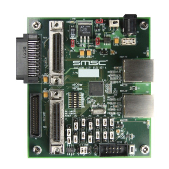
Page 3: Board Details
The following sections describe the various board features, including jumpers, LEDs, test points, system connections, and switches. A top view of the EVB9303M is shown in Figure 2.1. Note: The LAN9303M device is RoHS compliant. However, support components on the EVB9303M board are not necessarily RoHS compliant. Power Switch +5V Power... - Page 4 LED1 circuit as a pull-up, and the LED2 circuit as a pull-down. To illuminate LED1, the LAN9303M will drive the cathode of the LED1 low. To illuminated LED2, the LAN9303M will drive the anode of the LED2 high.
- Page 5 All strap values are read during power-up and on the rising edge of the nRST signal. Once the strap value is set, the LAN9303M will drive the LEDs high or low for illumination according the strap value. For other designs which may use these pins as GPIOs or interrupts, refer to the LAN9303M datasheet for additional information.
- Page 6 LAN9303M Evaluation Board User Manual 2.1.2.2 Serial Management Jumpers Table 2.3 Jumpers - Serial Management JUMPER PAIR DESCRIPTION SETTINGS Set MNGT0 to “1” Serial management MNGT0 JP10, JP16 jumper (Note 2.3, Note 2.4) 2---3 Set MNGT0 to “0” 1---2 Set MNGT1 to “1”...
-
Page 7: Test Points
LAN9303M Evaluation Board User Manual LEDs Table 2.7 LEDs REFERENCE COLOR INDICATION (Note 2.7) LED1 Green +3.3V power active LED2 Green Full-duplex/Collision Port 1 LED3 Green Full-duplex/Collision Port 2 Green Link/Activity Port 1 Yellow Speed Port 1 Green Link/Activity Port 2... -
Page 8: System Connections
LAN9303M Evaluation Board User Manual System Connections Table 2.9 System Connections PLUG/HEADER DESCRIPTION PART 2-pin populated GND header 2-pin (1x2) header 2-pin populated GND header 2-pin (1x2) header MII female connector for external PHY AMP/Tyco 749069-4 MII female connector for external PHY... - Page 9 LAN9303M Evaluation Board User Manual 2.5.2 Port 0 Mode Table 2.11 Port 0 Mode Switches SWITCH DESCRIPTION FUNCTION Sets P0_MODE0 low when closed (on). S2-1 8-position DIP switch, position 1 Otherwise, the signal is pulled-up internally. (Note 2.8, Note 2.9) Sets P0_MODE1 low when closed (on).
- Page 10 LAN9303M Evaluation Board User Manual 2.5.3 Port 1 Mode Table 2.13 Port 1 Mode Switches SWITCH DESCRIPTION FUNCTION Sets P1_MODE0 low when closed (on). S2-5 8-position DIP switch, position 5 Otherwise, the signal is pulled-up internally. (Note 2.10, Note 2.11) Sets P1_MODE1 low when closed (on).
-
Page 11: Top View
LAN9303M Evaluation Board User Manual 2.5.4 Reset Table 2.15 Reset Switch SWITCH DESCRIPTION FUNCTION SW pushbutton Reset: Generates nRST Mechanicals Figure 2.3 details the EVB9303M mechanical dimensions. 0.275 0.192 0.240 0.240 Ø0.125 Ø0.125 TOP VIEW Ø0.125 Ø0.125 0.240 0.240 0.275 0.192...
Need help?
Do you have a question about the LAN9303M and is the answer not in the manual?
Questions and answers