Table of Contents
Advertisement
Quick Links
EVB8700 Evaluation Board User Manual
Copyright © 2010 SMSC or its subsidiaries. All rights reserved.
Circuit diagrams and other information relating to SMSC products are included as a means of illustrating typical applications. Consequently, complete information
sufficient for construction purposes is not necessarily given. Although the information has been checked and is believed to be accurate, no responsibility is assumed
for inaccuracies. SMSC reserves the right to make changes to specifications and product descriptions at any time without notice. Contact your local SMSC sales office
to obtain the latest specifications before placing your product order. The provision of this information does not convey to the purchaser of the described semiconductor
devices any licenses under any patent rights or other intellectual property rights of SMSC or others. All sales are expressly conditional on your agreement to the terms
and conditions of the most recently dated version of SMSC's standard Terms of Sale Agreement dated before the date of your order (the "Terms of Sale Agreement").
The product may contain design defects or errors known as anomalies which may cause the product's functions to deviate from published specifications. Anomaly sheets
are available upon request. SMSC products are not designed, intended, authorized or warranted for use in any life support or other application where product failure
could cause or contribute to personal injury or severe property damage. Any and all such uses without prior written approval of an Officer of SMSC and further testing
and/or modification will be fully at the risk of the customer. Copies of this document or other SMSC literature, as well as the Terms of Sale Agreement, may be obtained
by visiting SMSC's website at http://www.smsc.com. SMSC is a registered trademark of Standard Microsystems Corporation ("SMSC"). Product names and company
names are the trademarks of their respective holders.
SMSC DISCLAIMS AND EXCLUDES ANY AND ALL WARRANTIES, INCLUDING WITHOUT LIMITATION ANY AND ALL IMPLIED WARRANTIES OF
MERCHANTABILITY, FITNESS FOR A PARTICULAR PURPOSE, TITLE, AND AGAINST INFRINGEMENT AND THE LIKE, AND ANY AND ALL WARRANTIES
ARISING FROM ANY COURSE OF DEALING OR USAGE OF TRADE. IN NO EVENT SHALL SMSC BE LIABLE FOR ANY DIRECT, INCIDENTAL, INDIRECT,
SPECIAL, PUNITIVE, OR CONSEQUENTIAL DAMAGES; OR FOR LOST DATA, PROFITS, SAVINGS OR REVENUES OF ANY KIND; REGARDLESS OF THE
FORM OF ACTION, WHETHER BASED ON CONTRACT; TORT; NEGLIGENCE OF SMSC OR OTHERS; STRICT LIABILITY; BREACH OF WARRANTY; OR
OTHERWISE; WHETHER OR NOT ANY REMEDY OF BUYER IS HELD TO HAVE FAILED OF ITS ESSENTIAL PURPOSE, AND WHETHER OR NOT SMSC HAS
BEEN ADVISED OF THE POSSIBILITY OF SUCH DAMAGES.
USER MANUAL
SMSC LAN8700
Revision 1.0 (02-23-10)
Advertisement
Table of Contents

Related Manuals for SMSC EVB8700


Summary of Contents for SMSC EVB8700
- Page 1 Any and all such uses without prior written approval of an Officer of SMSC and further testing and/or modification will be fully at the risk of the customer. Copies of this document or other SMSC literature, as well as the Terms of Sale Agreement, may be obtained by visiting SMSC’s website at http://www.smsc.com.
-
Page 2: Pin Connector
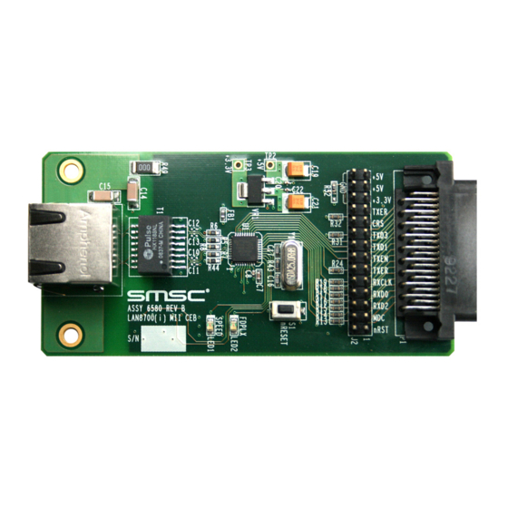
(BLW) correction, and clock and data recovery functions. The EVB8700 is an Evaluation Board (EVB) that interfaces a standard 40-pin female MII connector from an existing MAC controller to the SMSC LAN8700 Ethernet PHY, and out to an RJ45 Ethernet Jack for 10/100 connectivity. -
Page 3: Board Details
Mechanicals Power Power is normally supplied to the EVB8700’s +3.3V regulator externally via the +5V power pins of the MII connector. If desired, the EVB8700 can be powered without +5V present on the MII connector by supplying +5V to the TP2 test point with ground connected to pin 20 of header J2. - Page 4 Table 2.1 details the proper configuration required for each PHY address value. By default, all EVB8700 PHY address straps are configured to a value of “1”. Note: The PHYAD1 and PHYAD2 LEDs may function active-high or active-low depending on the boards PHY address configuration.
-
Page 5: Boot Mode Configuration
All capable. Auto-negotiation enabled (Default) Unpopulated Unpopulated Unpopulated Note 2.1 Refer to the LAN8700 Datasheet for additional information on Repeater mode. Note 2.2 Refer to the LAN8700 Datasheet for additional information on Power-Down mode. USER MANUAL SMSC LAN8700 Revision 1.0 (02-23-10) -
Page 6: Test Points
The nINT, TX_ER, and TXD4 functions share a common LAN8700 pin. This pin can operate in two functional modes: nINT (Interrupt) Mode and TX_ER/TXD4 Mode. The RXD3/nINTSEL pin is used to select one of these two modes. The EVB8700 must be properly configured for each mode as follows: nINT Mode (Default EVB8700 Mode) The nINTSEL configuration strap is pulled-up internally (by default) to select nINT mode. - Page 7 J2 location, as determined by the nINTSEL configuration strap value. Refer to Section 2.2.3, "nINT/TX_ER/TXD4 Pin Configuration," on page 6 for additional information. 2.2.6 Switches Table 2.7 Switches SWITCH DESCRIPTION FUNCTION Reset switch When pressed, triggers a board reset USER MANUAL SMSC LAN8700 Revision 1.0 (02-23-10)
-
Page 8: Top View
LAN8700 Evaluation Board User Manual Mechanicals Figure 2.2 details the EVB8700 mechanical dimensions. 0.255 0.175 Ø0.125 TOP VIEW Ø0.125 0.175 0.255 3.530 Figure 2.2 EVB8700 Mechanicals USER MANUAL Revision 1.0 (02-23-10) SMSC LAN8700... - Page 9 LAN8700 Evaluation Board User Manual 3 User Manual Revision History Table 3.1 Revision History REVISION LEVEL & DATE SECTION/FIGURE/ENTRY CORRECTION Rev. 1.0 Initial Release (02-23-10) USER MANUAL SMSC LAN8700 Revision 1.0 (02-23-10)
- Page 10 Mouser Electronics Authorized Distributor Click to View Pricing, Inventory, Delivery & Lifecycle Information: Microchip EVB8700...
Need help?
Do you have a question about the EVB8700 and is the answer not in the manual?
Questions and answers