Advertisement
Quick Links
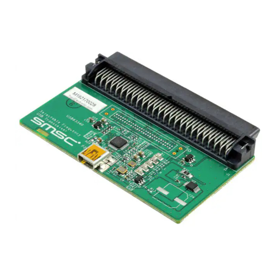
EVB-USB3340 USB Transceiver
Evaluation Board User Manual
Copyright © 2010 SMSC or its subsidiaries. All rights reserved.
Circuit diagrams and other information relating to SMSC products are included as a means of illustrating typical applications. Consequently, complete information
sufficient for construction purposes is not necessarily given. Although the information has been checked and is believed to be accurate, no responsibility is assumed
for inaccuracies. SMSC reserves the right to make changes to specifications and product descriptions at any time without notice. Contact your local SMSC sales office
to obtain the latest specifications before placing your product order. The provision of this information does not convey to the purchaser of the described semiconductor
devices any licenses under any patent rights or other intellectual property rights of SMSC or others. All sales are expressly conditional on your agreement to the terms
and conditions of the most recently dated version of SMSC's standard Terms of Sale Agreement dated before the date of your order (the "Terms of Sale Agreement").
The product may contain design defects or errors known as anomalies which may cause the product's functions to deviate from published specifications. Anomaly
sheets are available upon request. SMSC products are not designed, intended, authorized or warranted for use in any life support or other application where product
failure could cause or contribute to personal injury or severe property damage. Any and all such uses without prior written approval of an Officer of SMSC and further
testing and/or modification will be fully at the risk of the customer. Copies of this document or other SMSC literature, as well as the Terms of Sale Agreement, may be
obtained by visiting SMSC's website at http://www.smsc.com. SMSC is a registered trademark of Standard Microsystems Corporation ("SMSC"). Product names and
company names are the trademarks of their respective holders.
SMSC DISCLAIMS AND EXCLUDES ANY AND ALL WARRANTIES, INCLUDING WITHOUT LIMITATION ANY AND ALL IMPLIED WARRANTIES OF
MERCHANTABILITY, FITNESS FOR A PARTICULAR PURPOSE, TITLE, AND AGAINST INFRINGEMENT AND THE LIKE, AND ANY AND ALL WARRANTIES
ARISING FROM ANY COURSE OF DEALING OR USAGE OF TRADE. IN NO EVENT SHALL SMSC BE LIABLE FOR ANY DIRECT, INCIDENTAL, INDIRECT,
SPECIAL, PUNITIVE, OR CONSEQUENTIAL DAMAGES; OR FOR LOST DATA, PROFITS, SAVINGS OR REVENUES OF ANY KIND; REGARDLESS OF THE
FORM OF ACTION, WHETHER BASED ON CONTRACT; TORT; NEGLIGENCE OF SMSC OR OTHERS; STRICT LIABILITY; BREACH OF WARRANTY; OR
OTHERWISE; WHETHER OR NOT ANY REMEDY OF BUYER IS HELD TO HAVE FAILED OF ITS ESSENTIAL PURPOSE, AND WHETHER OR NOT SMSC HAS
BEEN ADVISED OF THE POSSIBILITY OF SUCH DAMAGES.
USER MANUAL
SMSC USB3340 EVB
Revision 1.1 (12-14-10)
Advertisement

Subscribe to Our Youtube Channel
Related Manuals for SMSC EVB-USB3340


Summary of Contents for SMSC EVB-USB3340
- Page 1 Any and all such uses without prior written approval of an Officer of SMSC and further testing and/or modification will be fully at the risk of the customer. Copies of this document or other SMSC literature, as well as the Terms of Sale Agreement, may be obtained by visiting SMSC’s website at http://www.smsc.com.
-
Page 2: User Manual
The board edge connector meets the UTMI+ Low Pin Interface (ULPI) Standard requirements for the T&MT connector. A link to the ULPI Working Group Page is available at www.smsc.com or may be obtained from your local FAE. The USB3340 EVB includes USB3340 packaged silicon and all external components required for the USB transceiver function. -
Page 3: Usb Connector
EVB-USB3340 USB Transceiver Evaluation Board User Manual Edge Connector for Digital I/O The T&MT edge connector is compliant to the ULPI specification. Part numbers and manufacturers for this connector and it’s mate are given in Table 2.1. Table 2.1 Edge Connector on the USB3340 EVB... - Page 4 EVB-USB3340 USB Transceiver Evaluation Board User Manual ULPI Signal Test Points Probe points at location J2, provide access to all ULPI signals. Install the Tektronix logic analyzer probe retention kit at J2 to probe these signals. Ordering information for the retention kit is provided in the bill of materials.
- Page 5 EVB-USB3340 USB Transceiver Evaluation Board User Manual 2.13 T&MT Pin Description The T&MT signal names, pin number and function are described in Table 43 and Table 44 of the ULPI Specification rev 1.1. The USB3340 EVB fully implements a ULPI compliant interface to the T&MT connector, including support for ULPI Clock Input Mode.
-
Page 6: Getting Started
EVB-USB3340 USB Transceiver Evaluation Board User Manual 3 Getting Started The block diagram in Figure 3.1 gives a simplified view of the USB3340 EVB. The USB3340 EVB is ready for device operation. To modify the board for OTG or Host applications, refer to Section 2.10... - Page 7 EVB-USB3340 USB Transceiver Evaluation Board User Manual The voltage at C3 should be approximately 3.3V. This is the USB3340 internal 3.3V voltage regulator output. The voltage at C4 should be 1.8V. This is the 1.8V regulator output. 4 Protecting VBUS from Non-Compliant VBUS Voltages The USB3340 is fully tolerant to VBUS voltages up to 30V.
- Page 8 EVB-USB3340 USB Transceiver Evaluation Board User Manual 5 USB3340 EVB Schematic Figure 5.1 USB3340 EVB Schematic Revision 1.1 (12-14-10) SMSC USB3340 EVB USER MANUAL...
- Page 9 EVB-USB3340 USB Transceiver Evaluation Board User Manual 6 USB3340 EVB Bill of Materials Figure 6.1 USB3340 EVB Bill of Materials SMSC USB3340 EVB Revision 1.1 (12-14-10) USER MANUAL...
- Page 10 EVB-USB3340 USB Transceiver Evaluation Board User Manual 7 User Manual Revision History Table 7.1 Customer Revision History REVISION LEVEL & DATE SECTION/FIGURE/ENTRY CORRECTION Rev. 1.1 (12-14-10) R9 on Schematic and BOM Changed from 10k to 169k Rev. 1.0 (05-01-10) Initial Release Revision 1.1 (12-14-10)
Need help?
Do you have a question about the EVB-USB3340 and is the answer not in the manual?
Questions and answers