Advertisement
Quick Links
PLEASE LEAVE WITH HOMEOWNER
Serial Number _________ Date of Purchase __________Point of Purchase _________________
HV1000
under-the-eaves attic space. Cooler outside air should be able to move through the window, the space that needs to be
cooled, and exhaust out through the fan into the attic.
Before installing your HV: Read all instructions carefully
► Some state and local electrical codes require fan products be installed by a licensed electrician. Check with your local
code officials before installation.
► Make sure that you have adequate net free exhaust area out of your attic. A minimum of 2 square feet is required for
the HV1000 and 3-1/2 square feet for the HV1600. This can be accomplished with a combination of roof, ridge, soffit or
gable end vents or other attic exhaust points.
► Make sure that there is enough clearance for the doors to open. Minimum requirement for the HV with R22 insulating
doors (HV1000 and HV1600-GR) is 11" and 12" for models with R38 insulating doors (HV1000-DB and HV1600-GDR).
► Make sure that there aren't any pipes, wires, rafters, or air conditioning or heating ducts running through the space
where the HV will be installed and that the doors will face an unoccupied area.
Unpacking your HV:
HV1000 (silver faced insulation)
One (1) HV1000 Whole House Cooler
One (1) White Metal Grille w/(6) Screws
One (1) Package of Foam Gasket
One (1) Metal Electrical Box Cover w/(2) Screws
One (1) Wall Switch (SPST)
Four (4) #8x3/4 Screws
One (1) Grounding Screw (green)
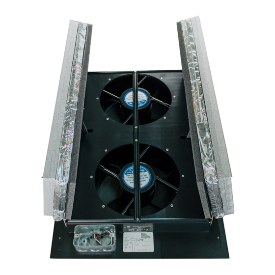
Please note the serial number, date of purchase and the point of purchase on the top of this page for handy
reference. The serial number is located on a label affixed to the HV next to the junction/utility box.
©Tamarack Technologies, Inc.• 320 Main Street • Buzzards Bay, MA 02532
508-759-4660 • 800-222-5932 • Fax 508-759-6001
Product Manual & Installation Guide
What the HV whole house cooling fans do
The HV is used to assist the natural cooling process in the house. When the
outside temperature drops below the inside temperature, the cooler outside air
can be used to cool the house. The HV will pull the cooler air from the outside,
through the house, up into the attic and push the hot air outside. The HV is a fan
product and will not cool the house below the outside air temperature or create
a noticeable breeze. The HV can be used any time, for as long as needed, to
cool or change the air in the house.
The best location for your HV
The HV should be located as central as possible to the area that you want to
cool. Above a central hallway or at the top of a stairwell provide the best airflow.
The fan can also be mounted vertically, exhausting through a knee wall into an
When you have unpacked your HV carefully you will find the following:
HV1600 (gold faced insulation)
One (1) HV1600 Whole House Cooler
One (1) White Metal Grille w/(6) Screws
One (1) Package of Foam Gasket
Four (4) #8x3/4 Screws
One (1) Hand Held Remote Transmitter
Whole House Cooling Fans
Warning: Not to be used over cooking appliances.
HV Series
HVM.02
DO NOT
PULL ON,
CARRY BY
OR STRESS
THE DOORS
www.tamtech.com
Advertisement

Related Manuals for Tamarack Technologies HV1000


Summary of Contents for Tamarack Technologies HV1000
- Page 1 ► Make sure that you have adequate net free exhaust area out of your attic. A minimum of 2 square feet is required for the HV1000 and 3-1/2 square feet for the HV1600. This can be accomplished with a combination of roof, ridge, soffit or gable end vents or other attic exhaust points.
- Page 2 Figure 4 Be sure at least one window is open when the fan is operating HV1000 - The HV1000 is operated by the wall switch installed per the wiring instructions. HV1600 - The HV1600 is controlled by the hand held remote transmitter. Button 1 is used to turn the unit On/Off and button 2 for High/Low.
-
Page 3: Specifications
The HV whole house cooling fans are not for use with solid state speed controls A Remote Control Kit for the HV1000 is available and may be purchased separately. Installation is quick and easy and it may be installed at any time. -
Page 4: Troubleshooting
The most common problem with the HV1000 is caused by incorrect wiring. Before you check anything else make sure: WHITE wire in HV1000 is connected to 115 VAC Line Neutral; RED wire in HV1000 is connected to 115 VAC Line Hot (Constant Hot Feed);...