Sun Microsystems StorageTek 2500 Series Hardware Installation Manual
Hide thumbs
Also See for StorageTek 2500 Series:
- Hardware installation manual (168 pages) ,
- Release notes (26 pages)

Related Manuals for Sun Microsystems StorageTek 2500 Series


Summary of Contents for Sun Microsystems StorageTek 2500 Series
- Page 1 Sun StorageTek 2500 Series Array ™ Hardware Installation Guide Sun Microsystems, Inc. www.sun.com Part No. 820-0015-10 March 2007 Submit comments about this document at: http://www.sun.com/hwdocs/feedback...
- Page 2 Products bearing SPARC trademarks are based upon an architecture developed by Sun Microsystems, Inc. The OPEN LOOK and Sun™ Graphical User Interface was developed by Sun Microsystems, Inc. for its users and licensees. Sun acknowledges the pioneering efforts of Xerox in researching and developing the concept of visual or graphical user interfaces for the computer industry. Sun holds a non-exclusive license from Xerox to the Xerox Graphical User Interface, which license also covers Sun’s licensees who implement OPEN...
-
Page 3: Table Of Contents
Contents Preface xiii Tray Overviews 1 Front-Access Components of the Trays 2 LEDs on the Front of the Trays 3 Rear-Access Components of the Trays 5 Controllers 6 Sun StorageTek 2540 Array 6 SFP Transceivers 7 Sun StorageTek 2530 Array 8 Controller Tray and Drive Expansion Tray Power-Fan Assembly 9 Sun StorageTek 2501 Array 10 Drive Expansion Tray IOM 10... - Page 4 Cabling an Expansion Tray to a Controller Tray 45 Cabling an Expansion Tray to Another Expansion Tray 45 Drive Module Cable Labeling 47 Example Label Abbreviation 47 Simplex Configurations 47 Next Steps 48 Sun StorageTek 2500 Series Array Hardware Installation Guide • March 2007...
- Page 5 Connecting the Management Host and Data Hosts 49 Connecting the Management Host 49 Attaching the Ethernet Ports to the LAN of the Management Host 50 Attaching the Ethernet Ports to the Management Host Using an Ethernet Hub 51 Attaching the Ethernet Ports Directly to the Management Host With a Cross- Over Cable 51 Connecting Data Hosts to the 2540 Array 51 2540 Array Data Host Connection Topologies 52...
- Page 6 Setting Up a Windows 2000 Advanced Server 86 Installing the DHCP Server 87 Configuring the DHCP Server 87 Using DC Power 91 DC Power Overview 91 Installation Notes for DC Power 92 Sun StorageTek 2500 Series Array Hardware Installation Guide • March 2007...
- Page 7 Ship Kit Changes 93 DC Power LEDS 93 Connecting Power Cables 94 ▼ Connecting the Cables 95 Turning Off the DC Power During an Emergency 96 Relocation Cautions 96 Glossary 97 Index 107 Contents...
- Page 8 Sun StorageTek 2500 Series Array Hardware Installation Guide • March 2007...
- Page 9 Figures FIGURE 1-1 Sun StorageTek 2500 Series Array Product Overview 2 FIGURE 1-2 Tray Front-Access Components 3 FIGURE 1-3 Location of the LEDs on the Front of the Trays 4 FIGURE 1-4 Controller Tray Rear-Access Components 5 FIGURE 1-5 Drive Expansion Tray Rear-Access Components 6...
- Page 10 FIGURE B-1 Power Fan Assembly Locations. 92 FIGURE B-2 DC Power Connector Cable and Source Wires 92 FIGURE B-3 DC Power Module LEDs, Power Switch, and Power Cable Receptacle. 93 Sun StorageTek 2500 Series Array Hardware Installation Guide • March 2007...
- Page 11 Descriptions of the Disk Drive LEDs 18 TABLE 1-7 Disk Drive States Represented by the LEDs 19 TABLE 1-8 Sun StorageTek 2500 Series Array Hardware Installation Checklist 20 TABLE 2-1 Controller and Expansion Tray Configurations 43 TABLE 6-1 RJ45 to DIN Serial Cable Pinouts 76 TABLE B-1 DC Power Module LEDs.
- Page 12 Sun StorageTek 2500 Series Array Hardware Installation Guide • March 2007...
-
Page 13: Preface
Manager Software Installation Guide. Before You Read This Book Before you begin to install the Sun StorageTek 2500 Series array, you must have already prepared the site as described in these books: Sun StorageTek 2500 Series Array Regulatory and Safety Compliance Manual ■... -
Page 14: Related Documentation
How This Book Is Organized Chapter 1 provides an overview of the Sun StorageTek 2500 Series array and the hardware installation process. Chapter 2 describes how to install rack-mounting rails, controller modules, and expansion cabinets in three Sun cabinets. Chapter 3 describes how to connect the management host and data hosts to enable access to the array. - Page 15 Instructions for installing Sun Rack Installation Guide 816-6386-nn the Sun Rack 900/1000 cabinets In addition, the Sun StorageTek 2500 Series Array includes the following online documentation: Sun StorageTek Common Array Manager online help ■ Contains system overview and configuration information.
- Page 16 You can submit your comments by going to: http://www.sun.com/hwdocs/feedback Please include the title and part number of your document with your feedback: Sun StorageTek 2500 Series Array Hardware Installation Guide, part number 820-0015-10. xvi Sun StorageTek 2500 Series Array Hardware Installation Guide • March 2007...
-
Page 17: Tray Overviews
C H A P T E R Tray Overviews The Sun StorageTek 2540 Array, the Sun StorageTek 2530 Array, and the Sun StorageTek 2501 Array are a family of storage products that provide high-capacity, high-reliability storage in a compact configuration. The Sun StorageTek 2540 Array is a modular, rackmountable controller tray. -
Page 18: Front-Access Components Of The Trays
The disk drives in your controller tray might differ in appearance from those shown in FIGURE 1-2. The variation does not affect the function of the disk drives. Sun StorageTek 2500 Series Array Hardware Installation Guide • March 2007... -
Page 19: Leds On The Front Of The Trays
The front-access components include the following: End caps – Plastic, removable caps on the right and left side of the tray. Numbers ■ on the side of the right end cap indicate the numbering of the drives. LEDs (light emitting diodes) – Four LEDs located on the on the left-side end cap ■... -
Page 20: Figure 1-3 Location Of The Leds On The Front Of The Trays
Over Amber The tray temperature has The tray temperature is within Temperature reached an unsafe level. operational range. Power Green Power is present. Power is not present. Sun StorageTek 2500 Series Array Hardware Installation Guide • March 2007... -
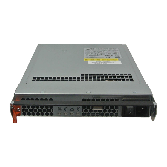
Page 21: Rear-Access Components Of The Trays
Rear-Access Components of the Trays Components that are accessed from the rear of the Sun StorageTek 2540 Array and the Sun StorageTek 2530 Array controller trays include: Controller Modules – Two removable controller modules. ■ Power-fan assembly – Two removable power supply modules with cooling fans. ■... -
Page 22: Controllers
ID numbers on both of the controllers in one controller tray are identical under optimal operating conditions. Sun StorageTek 2540 Array This Fibre Channel (FC) controller tray provides the following capabilities: Sun StorageTek 2500 Series Array Hardware Installation Guide • March 2007... -
Page 23: Sfp Transceivers
Two data host connectors per controller that can support either a fiber-optic ■ interface or a copper interface with 1, 2, or 4 Gb/s data host connection speed One drive expansion tray Serial Attached SCSI (SAS) connector with 3 Gb/s drive ■... -
Page 24: Sun Storagetek 2530 Array
One drive expansion tray SAS connector for the drive channel with 3 Gb/s drive ■ expansion tray connection speed 512-MB or 1-GB mirrored cache ■ Maximum connection of 36 disk drives (one controller tray and two drive ■ expansion trays) Sun StorageTek 2500 Series Array Hardware Installation Guide • March 2007... -
Page 25: Controller Tray And Drive Expansion Tray Power-Fan Assembly
Sun StorageTek 2530 Array Controller Connectors FIGURE 1-8 1. Drive Expansion Tray Connector (SAS Out) 2. Ethernet Management Host Connector 3. SAS Data Host Connectors 4. RS-232 Connector (Diagnostics Port) Controller Tray and Drive Expansion Tray Power- Fan Assembly The power-fan assembly for the Sun StorageTek 2540 Array, the Sun StorageTek 2530 Array, and the Sun StorageTek 2501 Array is identical and interchangeable. -
Page 26: Sun Storagetek 2501 Array
If the cable is plugged into two connectors with arrows of the same direction, communication between the two drive expansion trays is lost. Sun StorageTek 2500 Series Array Hardware Installation Guide • March 2007... -
Page 27: Leds On The Rear Of The Trays
LEDs on the Rear of the Trays Controller LEDs on the Sun StorageTek 2540 Array Locations of the Controller LEDs on the Sun StorageTek 2540 Array FIGURE 1-10 Descriptions of the Controller LEDs on the Sun StorageTek 2540 Array (1 of TABLE 1-2 Location Color... -
Page 28: Controller Leds On The Sun Storagetek 2530 Array
All links have failed. Link Fault Amber At least one link has an error. Normal condition. Battery Fault Amber Indicates a fault within the Normal condition. battery backup unit. Sun StorageTek 2500 Series Array Hardware Installation Guide • March 2007... -
Page 29: Controller Tray And Drive Expansion Tray Power-Fan Assembly Leds
Descriptions of the Controller LEDs on the Sun StorageTek 2530 Array (2 of TABLE 1-3 Location Color Cache Active Green Caching is enabled. Indicates a problem if caching is enabled. When blinking, the cache has data. Service Action Blue The controller can be removed The controller cannot be Allowed from the controller tray. -
Page 30: Figure 1-12 Locations Of The Power-Fan Assembly Leds
Fault Amber A fault exists within the Normal condition power-fan assembly. Power (AC Good) Green Power is present Power is not present Sun StorageTek 2500 Series Array Hardware Installation Guide • March 2007... -
Page 31: Iom Leds On The Sun Storagetek 2501 Array
IOM LEDs on the Sun StorageTek 2501 Array Locations of the IOM LEDs FIGURE 1-13 Descriptions of the IOM LEDs TABLE 1-5 Location Color IOM Link Fault Amber A link error occurred. No errors have occurred. IOM Link Green The link is active. A link error occurred. -
Page 32: Disk Drives
Advisor to determine the action you should take. Disk Drives Disk drives for the Sun StorageTek 2500 Series Array have three components: a hard drive, a hard drive carrier, and an adapter card for connecting the disk drive to the midplane. -
Page 33: Figure 1-14 Disk Drives
Disk Drives FIGURE 1-14 The physical locations of the disk drives are numbered 1 through 12, from left to right, and from top to bottom. The right end cap has numbers on the side showing the numbers of the adjacent drives. The Common Array Manager Service Advisor software automatically detects a disk drive’s tray ID and slot designation. -
Page 34: Leds On The Disk Drives
On – The power is on and the disk drive is operating normally. On and blinking (0.5 s on, 0.5 s off) –Disk drive I/O activity is taking place. Sun StorageTek 2500 Series Array Hardware Installation Guide • March 2007... -
Page 35: Common Array Manager Software
On, solid offline. Common Array Manager Software The Sun StorageTek 2500 Series Array is managed by the Sun StorageTek Common Array Manager software. The Common Array Manager provides web browser– based management and configuration from an external management host, data host... -
Page 36: Overview Of The Installation Process
Overview of the Installation Process Before you begin to install the array, you must do the following: Read the Sun StorageTek 2500 Series Array Release Notes for any late-breaking ■ information related to the installation of the array. Prepare the site as described in these books: ■... - Page 37 Sun StorageTek 2500 Series Array Hardware Installation Checklist TABLE 1-8 Step Installation Task Where to Find Procedure Connect the management host. “Connecting the Management Host” on page 49 Attach the host interface cables. “Connecting Data Hosts to the 2540 Array” on page 51 Turn on the power.
- Page 38 Sun StorageTek 2500 Series Array Hardware Installation Guide • March 2007...
-
Page 39: Installing Trays
This chapter describes the process of installing the Sun StorageTek 2500 Series Array. It contains the following sections: “Preparing for the Installation” on page 24 ■... -
Page 40: Preparing For The Installation
“Preparing the Cabinet” on page 26 ■ Preparing the Universal Rail Kit Use the universal rail kit to mount the Sun StorageTek 2500 Series Array trays in any of the following cabinets: Any standard Sun cabinet, such as the Sun Rack 900/1000 cabinet ■... -
Page 41: Preparing The Tray
A traycan weigh up to 54.3 pounds (24.6 kg). 1. Unpack the tray. 2. Check the contents of the box for the following items: Sun StorageTek 2500 Series Arraytrays (controller or expansion) ■ Ship kit for the controller tray ■... -
Page 42: Preparing The Cabinet
Next, install the expansion trays for the first controller tray. If room remains in the cabinet, repeat for the next controller and expansion trays. Starting at the bottom distributes the weight correctly in the cabinet. Sun StorageTek 2500 Series Array Hardware Installation Guide • March 2007... -
Page 43: Attaching The Rails To A Cabinet
Attaching the Rails to a Cabinet Depending on the type of cabinetin which you will install the tray, use one of the following procedures to attach the rails: “Attaching the Universal Rail Kit to a Standard Sun or 19-Inch Cabinet With ■... -
Page 44: Figure 2-2 Positioning The Front Of The Left Rail Behind The Left Front Cabinet Rail
2. Insert the 8-32 screws through the center holes in each RU of the rack into the top and bottom holes in the Universal rail ( FIGURE 2-3 These screws pass through the cabinet rail holes and screw into threaded holes in the Universal rail. Sun StorageTek 2500 Series Array Hardware Installation Guide • March 2007... -
Page 45: Figure 2-3 Securing The Left Rail To The Front Of The Cabinet
Securing the Left Rail to the Front of the Cabinet FIGURE 2-3 3. Repeat Step 1 Step 2 for the right rail. 4. At the back of the cabinet, adjust the length of the left rail as needed to fit the cabinet, and position the rail flange behind the face of the cabinet rail FIGURE 2-4 Chapter 2 Installing Trays... -
Page 46: Figure 2-4 Adjusting The Length Of The Left Rail At The Back Of The Cabinet
5. Align the rail flange so that the top and bottom mounting holes match the center holes in the RUs corresponding to those used on the front of the cabinet. Sun StorageTek 2500 Series Array Hardware Installation Guide • March 2007... -
Page 47: Attaching The Universal Rail Kit To A Standard 19-Inch Cabinet With Unthreaded Cabinet Rails
6. Insert the 8-32 screws through the center holes of the rack into the top and bottom mounting holes on the universal rail ( FIGURE 2-5 Securing the Left Rail to the Back of the Cabinet FIGURE 2-5 7. Repeat Step Step 5, and... -
Page 48: Figure 2-6 Inserting The Cabinet Rail Adapter Plate On The Cabinet Rail
The hook on the top of the adapter plate hooks into the top hole of the upper RU. The flat flange on the bottom of the adapter plate fits into the bottom hole of the lower RU ( FIGURE 2-7 Sun StorageTek 2500 Series Array Hardware Installation Guide • March 2007... -
Page 49: Figure 2-7 Adapter Plate In Place On The Cabinet Rail
Adapter plate in place on the Cabinet Rail. FIGURE 2-7 2. Slide the front flange of the universal rail between the front cabinet rail and the top hook of the rail adater plate ( FIGURE 2-8 Chapter 2 Installing Trays... -
Page 50: Figure 2-8 Slide The Flange Of The Rail Behind The Cabinet Rail And Between That And The Hook Of The Rail Adapter Plat.e, As Shown
3. Insert and tighten two 8-32 screws through the top and bottom holes in the adapter plate, through the cabinet rail, and into the top and bottom threaded holes in the universal rail mounting flange ( FIGURE 2-9 Sun StorageTek 2500 Series Array Hardware Installation Guide • March 2007... -
Page 51: Figure 2-9 Securing The Rail To The Front Left Of The Cabinet
Securing the Rail to the Front left of the Cabinet FIGURE 2-9 Step 1 Step 3 4. Repeat through on the corresponding cabinet rail at the back of the cabinet ( FIGURE 2-10 Mounting the rail on the back of the cabinet is the same as mounting it to the front, after you extend the rail the necessary length to reach the rear cabinet rail. -
Page 52: Figure 2-10 Adjusting The Length Of The Rail At The Back Of The Cabinet
FIGURE 2-11 The screws passes through the unthreaded holes of the adapter plate and cabinet rail mounting rail and screw into the threaded holes of the rail mounting flange. Sun StorageTek 2500 Series Array Hardware Installation Guide • March 2007... -
Page 53: Installing A Tray In A Cabinet
Securing the Rail to the Back of the Cabinet FIGURE 2-11 For extra stability, you can tighten the rail screws as in FIGURE 2-1 6. Repeat Step 1 through Step 5 to install the right rail. Installing a Tray in a Cabinet Install the controller tray in the first empty 2RU slot at the bottom of the cabinet. -
Page 54: Figure 2-12 Positioning The Tray In The Cabinet
Cabinet FIGURE 2-12 2. Carefully slide the tray into the cabinet until the front mounting flanges on the tray touch the vertical face of the cabinet ( FIGURE 2-13 Sun StorageTek 2500 Series Array Hardware Installation Guide • March 2007... -
Page 55: Figure 2-13 Array Controller Tray Installed
Array Controller Tray Installed FIGURE 2-13 The tray has mounting flanges on both sides with three mounting holes in them. The top and bottom holes are large enough to fit over the heads of the screws already in the cabinet rails used to mount the universal rails. If the tray was shipped with end caps (bezels) clipped on the tray mounting flanges, remove them before sliding the tray all the way in over the mounting screw heads. -
Page 56: Figure 2-14 Rail Clip And Rear Mounting Hole On Rear Of Array Tray
Rail clip and rear mounting hole on rear of array tray. FIGURE 2-14 3. Insert a single 8-32 pan head screw through the center hole in each front mounting flange and tighten ( FIGURE 2-15 Sun StorageTek 2500 Series Array Hardware Installation Guide • March 2007... -
Page 57: Figure 2-15 Securing The Tray To The Front Of A Sun Rack 900/1000 Cabinet
Tray Securing the to the Front of a Sun Rack 900/1000 Cabinet FIGURE 2-15 4. Replace the end caps (bezels) that cover the mounting flanges on the front of the array tray. On each front mounting flange, there is a small tab over which the end caps fit. The end caps have a slot on top for this tab. -
Page 58: Connecting The Power Cables
Each expansion tray has two SAS port connectors, one marked with an up arrow and the other marked with a down arrow ( ). You use SAS cables to FIGURE 2-17 connect expansion trays to controllers. Sun StorageTek 2500 Series Array Hardware Installation Guide • March 2007... -
Page 59: Array Configuration Naming Convention
Note – Perform all SAS connections from an Out (down arrow) port to an In (up arrow) port. If the cable is connected to two connectors with the same arrows, communication between the two drive modules will be lost. Expansion Ports on an Expansion Tray FIGURE 2-17 2 2 2 2 2 2 2 2... -
Page 60: Connecting Expansion Trays
FIGURE 2-19 On all SAS cables, affix a label to each end of the cable. See “Drive Module Cable ■ Labeling” on page 47 for labeling tips. Sun StorageTek 2500 Series Array Hardware Installation Guide • March 2007... -
Page 61: Cabling An Expansion Tray To A Controller Tray
Cabling an Expansion Tray to a Controller Tray A Controller tray has two expansion ports, one on the Controller A module and one on the Controller B module. To connect an expansion tray, connect an SAS cable from each expansion port on the controller to each In port on the expansion tray. shows a 1x2 array configuration consisting of one controller tray and one FIGURE 2-18 expansion tray. -
Page 62: Figure 2-19 1X3 Array Configuration Cabling
B-side expansion In port of expansion tray 2 ( FIGURE 2-19 5. Connect one SAS cable between the expansion tray 1 Out port and the A-side expansion In port of expansion tray 2 ( FIGURE 2-19 Sun StorageTek 2500 Series Array Hardware Installation Guide • March 2007... -
Page 63: Drive Module Cable Labeling
6. Connect one SAS cable between the expansion tray 2 B-side Out port and the B-side In port of expansion tray 2 ( FIGURE 2-19 Drive Module Cable Labeling Labels for the drive cables identify which controller ports and which expansion connections in an expansion tray you use when you attach cables between a controller and the drive modules on an expansion tray. -
Page 64: Next Steps
Write cache is by nature in write-through mode because there is no cache mirroring possible. Next Steps Now you are ready to connect the management and data hosts, as described in Chapter Sun StorageTek 2500 Series Array Hardware Installation Guide • March 2007... -
Page 65: Connecting The Management Host And Data Hosts
C H A P T E R Connecting the Management Host and Data Hosts This chapter describes Sun StorageTek 2500 Series Array cable connections for hosts. It contains the following sections: “Connecting the Management Host” on page 49 ■ “Connecting Data Hosts to the 2540 Array” on page 51 ■... -
Page 66: Attaching The Ethernet Ports To The Lan Of The Management Host
Controller B Note – Before you begin, ensure that the tworequired Ethernet cables are available. These requirements are outlined in the StorageTek 2500 Series Array Site Preparation Guide. There are three ways to establish a connection between the management host and Ethernet port 1 of an array controller: “Attaching the Ethernet Ports to the LAN of the Management Host”... -
Page 67: Attaching The Ethernet Ports To The Management Host Using An Ethernet Hub
Attaching the Ethernet Ports to the Management Host Using an Ethernet Hub To attach the Ethernet ports and the management port Ethernet interface to an Ethernet hub on a private subnet: 1. Locate Ethernet ports on Controller A and Controller B at the back of the controller tray ( FIGURE 3-1 2. -
Page 68: 2540 Array Data Host Connection Topologies
Direct connection from two data host servers ( ■ FIGURE 3-3 Data host connection through Fiber Channel switch fabric ( ■ FIGURE 3-4 Mixed connection, direct and through switch ( ■ FIGURE 3-5 Sun StorageTek 2500 Series Array Hardware Installation Guide • March 2007... -
Page 69: Figure 3-2 Direct Connection From A Single Data Host Server
Direct connection from a single data host server FIGURE 3-2 Direct Connection from two data host servers FIGURE 3-3 1. Host 2. HBA 1 3. HBA 2 4. Host Port 1 5. Host Port 2 6. Controller A 7. Controller B Data host connection through a Fibre Channel switch FIGURE 3-4 Chapter 3 Connecting the Management Host and Data Hosts... -
Page 70: 2540 Array Data Host Connections
Data transmission from the host to the array controller modules is through fiber- optic cables. The fiber-optic cables connect to the controllers through Small Form- factor Pluggable (SFP) transceivers ( FIGURE 3-6 Sun StorageTek 2500 Series Array Hardware Installation Guide • March 2007... -
Page 71: To Connect Data Hosts Using Fibre Channel
Connecting the SFP and Fiber-optic Cable to a 2540 Controller FIGURE 3-6 1. Fibre Channel Host Port 2. SFP is Inserted into the Host Port 3. Fiber-optic Cable is inserted into the SFP The Sun StorageTek 2540 Array controller tray has fourFC host connector ports, two per controller module. -
Page 72: Connecting Data Hosts To The 2530 Array
4. Host Connectors on the Controllers 5. Controller A 6. Controller B shows an example of direct host connections from two data hosts, each FIGURE 3-9 with dual HBAs. Sun StorageTek 2500 Series Array Hardware Installation Guide • March 2007... -
Page 73: Figure 3-9 Direct Connections From Two Data Hosts With Dual Hbas
Direct connections from two data hosts with dual HBAs. FIGURE 3-9 shows an example of direct host connections from three data hosts, each FIGURE 3-10 with dual HBAs. Direct connections from three data hosts with dual HBAs. FIGURE 3-10 Note – For maximum hardware redundancy, you must install a minimum of two HBAs in each host. -
Page 74: Figure 3-11 Sas Data Host Ports (On Back Of Tray)
4. Affix a label to each end of the cable. See “Host Cable Labeling” on page 59 information about cable labels. 5. Repeat these steps for each host-to-controller connection. Sun StorageTek 2500 Series Array Hardware Installation Guide • March 2007... -
Page 75: Host Cable Labeling
Host Cable Labeling Labels for host cabling identify which host HBA ports and which controller ports you use when you attach cables between the host and the controller. Cable labels are useful if you need to disconnect cables to service a controller. Attach a label to each end of the cable. - Page 76 Sun StorageTek 2500 Series Array Hardware Installation Guide • March 2007...
-
Page 77: Powering On The Array
C H A P T E R Powering On the Array This chapter describes initial tray power-on procedures. Perform the following procedures in the order listed: “Before Powering On” on page 61 ■ “Powering On the Array” on page 62 ■... -
Page 78: Powering On The Array
5. Check the status of each tray. After the power-on sequence is complete, confirm the following: The green OK/Power LEDs on each drive in the tray are steady on. ■ Sun StorageTek 2500 Series Array Hardware Installation Guide • March 2007... -
Page 79: Powering Off The Array
The green OK/Power LED on the tray is steady on. ■ If all tray and drive Ok/Power LEDs are steady green and the amber Service Required LEDs are off, the power-on sequence is complete and no faults have been detected. Powering Off the Array The array rarely needs to be powered off. -
Page 80: Next Steps
After you have connected the management host and data hosts, you are ready to install the management host software as described in the Sun StorageTek Common Array Manager Software Installation Guide and the data host software as described in Chapter Sun StorageTek 2500 Series Array Hardware Installation Guide • March 2007... -
Page 81: Data Hosts, Hbas, And Other Software
C H A P T E R Data Hosts, HBAs, and Other Software This chapter describes how to install data host software, HBAs, and other software on different host platforms. It contains the following sections: “Data Host Software” on page 65 ■... -
Page 82: Multipathing
The required versions of HBAdrivers must be installed on the data host before you can set up a data host. The Sun StorageTek 2500 Series Array Release Notes lists the data host requirements for HBAs and drivers. Refer to the specific vendor HBA documentation for instructions on installing HBA drivers. -
Page 83: To Obtain Sun Solaris 8 And 9 Data Host Software
The data host software version you need depends on your operating system. See the Sun StorageTek 2500 Series Array Release Notes for the current data host software requirements. Download the Solaris x (8 or 9) Base Package (if you do not already have it installed), and then the Install_it Script SAN 4.4.x version as... -
Page 84: To Obtain Traffic Manager For Operating Systems Other Than Solaris
The data host software version you need depends on your operating system. See the Sun StorageTek 2500 Series Array Release Notes for the current data host software requirements. There is a README file available on the download page with instructions for unpacking and installing the download file on your data host computer. -
Page 85: Installing Data Host Software For Operating Systems Other Than Solaris
Sun Redundant Dual Array Controller (RDAC), also known as MPP, and is available from the Sun Download Center (SDLC). See the Sun StorageTek 2500 Series Array Release Notes for a list of supported operating systems, patches, and HBAs. Downloading and Installing Sun RDAC Software 1. -
Page 86: Enabling Multipathing Software
1. Open the /kernel/drv/scsi_vhci.conf file with a text editor. 2. Set mpxio-disable=”no”; in the file. 3. Set load-balance=”round-robin”; in the file. 4. Set auto-failback=”enable”; in the file. 5. Save the updated file. 6. Reboot the host. Sun StorageTek 2500 Series Array Hardware Installation Guide • March 2007... -
Page 87: Enabling Multipathing Software For Solaris 10 Os
7. Use the cfgadm command to configure HBA paths. How you configure paths depends on how you are using your arrays in a SAN or direct attach environment. See the Sun StorageEdge SAN Foundation Software 4.4 Configuration Guide (www.sun.com/products-n-solutions/hardware /docs/Network_Storage_Solutions/SAN/san_software/) for information about configuring paths. - Page 88 Sun StorageTek 2500 Series Array Hardware Installation Guide • March 2007...
-
Page 89: Configuring Ip Addressing
“Configuring the IP Address of the Array Controllers” on page 74 ■ About IP Addressing The Sun StorageTek 2500 Series Array is managed out-of-band by way of a standard Ethernet connection between the redundant array of independent disk (RAID) controllers and your management host. -
Page 90: Configuring The Ip Address Of The Array Controllers
You can restore DHCP IP addressing to Ethernet port 1 of either controller in either of three ways: Start a DHCP server on the same subnet, then reboot the 2500 Series Array. ■ Sun StorageTek 2500 Series Array Hardware Installation Guide • March 2007... -
Page 91: Configuring Static Ip Addressing
Using the serial port interface (see “Using the Serial Port Interface to Assign IP ■ Addresses” on page Using the Sun StorageTek Common Array Manager (see the Sun StorageTek ■ Common Array Manager Software Installation Guide) Configuring Static IP Addressing There are two methods of assigning static IP addresses to the Ethernet ports of a controller: The serial port interface (see... -
Page 92: To Set Up The Terminal Emulation Program
To set up a terminal emulation program to connect to the serial port: 1. Select VT100 emulation. 2. Remove any modem strings from the connection profile. 3. Set up the connection profile with the following communication settings: Sun StorageTek 2500 Series Array Hardware Installation Guide • March 2007... -
Page 93: To Establish A Connection With The Serial Port
Data Rate: 38400 ■ Data Bits: 8 ■ Parity: None ■ Stop Bits: 1 ■ Flow Control: None ■ ▼ To Establish a Connection With the Serial Port To establish a connection with the serial port and display the Service Interface menu: 1. -
Page 94: To Configure The Ip Addresses
Note – If you are not using DHCP IP addressing and have a gateway IP address on your subnet, you must also specify a gateway IP address for the Ethernet port. This option displays only if the serial interface detects a gateway. Sun StorageTek 2500 Series Array Hardware Installation Guide • March 2007... - Page 95 Press '.' to clear the field; Press '-' to return to the previous field; Press <ENTER> and then ^D to quit (Keep Changes) Current Configuration New Configuration IP-address IP Address if1 : 192.168.128.101 Subnet Mask if1 : 255.255.255.0 <ENTER> Gateway IP Address if1: <ENTER>...
- Page 96 Sun StorageTek 2500 Series Array Hardware Installation Guide • March 2007...
-
Page 97: Configuring A Dhcp Server
C H A P T E R Configuring a DHCP Server This appendix describes how to configure bootstrap protocol (BOOTP) services in a Sun Solaris and Microsoft Windows environment. It contains the following sections: “Before You Begin” on page 81 ■... - Page 98 Network Address: Network address of Controller A ■ Subnet Mask: For example, 255.255.255.0 ■ Network Type: Local-Area (LAN) ■ Router: Use router discovery protocol ■ Your summary page should look similar to the following example: Sun StorageTek 2500 Series Array Hardware Installation Guide • March 2007...
- Page 99 3. Verify your configuration information and click Finish. 4. When you are prompted to configure addresses for the server, click Yes. The Add Address to Network wizard is displayed. 5. Enter the following information: Number of IP addresses ■ Name of managing server ■...
- Page 100 In each Client ID field, enter 01 followed by the MAC address that is printed on the back of the RAID controller. For example: 0100A0E80F924C b. Toward the bottom of the window, select “Assign only to BOOTP clients.” Sun StorageTek 2500 Series Array Hardware Installation Guide • March 2007...
- Page 101 c. Click OK. The DHCP manager updates the status and client ID, as shown in the following example: 8. Go to Modify Service Options and do the following: a. Select Detect Duplicate IP addresses. b. Under BOOTP Compatibility, select Automatic. c.
-
Page 102: Setting Up A Windows 2000 Advanced Server
IP addresses that are assigned to the RAID controllers do not conflict. ■ The array is in BOOTP IP addressing mode (the default setting for a new array). ■ The Windows 2000 Server setup CD is available. ■ Sun StorageTek 2500 Series Array Hardware Installation Guide • March 2007... -
Page 103: Installing The Dhcp Server
The following procedure provides an example of how to set up DHCP with the BOOTP option on the Windows 2000 Advanced Server. Your environment may require different steps. Installing the DHCP Server To install DHCP server on the Windows 2000 Advanced Server: 1. - Page 104 14. Power on or power cycle the array modules. 15. Click Address Leases in the left pane to check the DHCP server leases. The lease expiration displays the following status for each RAID controller: Reservation (active) Sun StorageTek 2500 Series Array Hardware Installation Guide • March 2007...
- Page 105 If the lease expiration for the controllers is inactive, try refreshing the list. If the lease is still inactive, check the following: Are the IP addresses allocated for BOOTP conflicting? ■ Were the correct MAC addresses added to the DHCP server for the array ■...
- Page 106 Sun StorageTek 2500 Series Array Hardware Installation Guide • March 2007...
-
Page 107: Using Dc Power
C H A P T E R Using DC Power This appendix describes using the DC Power Unit for the Sun StorageTek 2500 Series Arrays in the following sections: “DC Power Overview” on page 91 ■ “Installation Notes for DC Power” on page 92 ■... -
Page 108: Installation Notes For Dc Power
B-2) from the power supplies. DC Power Connector Cable and Source Wires FIGURE B-2 Installation Notes for DC Power The sections that follow provide hardware information about DC power. Sun StorageTek 2500 Series Array Hardware Installation Guide • March 2007... -
Page 109: Ship Kit Changes
“Ship Kit Changes” on page 93 ■ “DC Power LEDS” on page 93 ■ “Connecting Power Cables” on page 94 ■ “Turning Off the DC Power During an Emergency” on page 96 ■ “Relocation Cautions” on page 96 ■ Ship Kit Changes If the DC power option is ordered, two DC power connector cables are provided with each controller tray for connection to centralized DC power plant equipment. -
Page 110: Connecting Power Cables
DC power source and the array module for over-current and short-circuit protection. Before turning off any power switches on a DC-powered module, you must disconnect the two-pole 20-amp circuit breaker. Sun StorageTek 2500 Series Array Hardware Installation Guide • March 2007... -
Page 111: Connecting The Cables
Caution – Ensure that you do not turn on power to the array module or the connected drive modules until this guide instructs you to do so. For the proper procedure for turning on the power, see ““Connecting Power Cables” on page 94.”... -
Page 112: Turning Off The Dc Power During An Emergency
Verifying that the volume group and each of its associated volumes on the ■ affected array have an Optimal status. Determining the location and status of any global hot spares associated with the ■ affected storage array. Sun StorageTek 2500 Series Array Hardware Installation Guide • March 2007... -
Page 113: Glossary
Glossary Definitions obtained from the Storage Networking Industry Association (SNIA) Dictionary are indicated with “(SNIA)” at the end. For the complete SNIA Dictionary, go to www.snia.org/education/dictionary. agent The component of the system monitoring and diagnostic software that collects health and asset information about the array. alarm A type of event that requires service action. - Page 114 Any host that uses the system for storage. A data host can be connected directly to the array (direct attach storage, or DAS) or can be connected to an external switch that supports multiple data hosts (storage area network, or SAN). See also host. Sun StorageTek 2500 Series Array Hardware Installation Guide • March 2007...
- Page 115 data path The route taken by a data packet between a data host and the storage device. direct attached storage (DAS) A storage architecture in which one or two hosts that access data are connected physically to a storage array. disk A physical drive component that stores data.
- Page 116 (FRU). host bus adapter (HBA). host As a function of the Sun StorageTek 2500 Series array configuration, a representation of a data host that is mapped to initiators and volumes to create a storage domain. See also data host, initiator.
- Page 117 A Solaris host serving the configuration, management, and monitoring software for the Sun StorageTek 2500 Series array. The software on the station can be accessed with a browser to run the browser interface or with a remote scripting command- line interface (CLI) client to access the SSCS CLI commands.
- Page 118 The assembly that provides power management for the system. The redundant design uses two PDUs in each system so that the system’s data path continues to function if one of the PDUs fails. Sun StorageTek 2500 Series Array Hardware Installation Guide • March 2007...
- Page 119 profile storage profile. provisioning The process of allocation and assignment of storage to hosts. RAID An acronym for Redundant Array of Independent Disks, a family of techniques for managing multiple disks to deliver desirable cost, data availability, and performance characteristics to host environments. Also, a phrase adopted from the 1988 SIGMOD paper A Case for Redundant Arrays of Inexpensive Disks.
- Page 120 (SNIA). target The system component that receives a SCSI I/O command. (SNIA). Sun StorageTek 2500 Series Array Hardware Installation Guide • March 2007...
- Page 121 thin-scripting client remote scripting CLI client. tray storage tray. virtual disk A set of disk blocks presented to an operating environment as a range of consecutively numbered logical blocks with disk-like storage and I/O semantics. The virtual disk is the disk array object that most closely resembles a physical disk from the operating environment’s viewpoint.
- Page 122 Sun StorageTek 2500 Series Array Hardware Installation Guide • March 2007...
-
Page 123: Index
Index Numerics attaching rails to a Sun Rack 900/1000, 27 controller tray slot, 26 2500 series array product overview, 2 installing a tray, 37 preparing for tray installation, 26 cabling about installing data host software for non-Solaris 1x2 array configuration, 45 host, 69 1x3 array configuration, 45 about IP addressing, 73... - Page 124 67, 69, 70 connecting directly to management host, 51 data path redundancy, 6 connecting to a management LAN, 50 DC power option connecting using a hub, 51 Sun StorageTek 2500 Series Array Hardware Installation Guide • March 2007...
- Page 125 expansion tray on the rear of the trays, 11 ship kit contents, 26 power-fan assembly, 13 Service Action Allowed, 15 fans power-fan assembly, 9 MAC address, 6 fault LED, 16 MAC address location, 81 Fibre Channel management host ST2540 controller tray, 7 connecting, 49 connector cable types, 7 firmware, 6...
- Page 126 I/O module, 10 attaching to a standard 19-inch cabinet, 27 power-fan assembly, 9 attaching to a Sun Rack 900/1000, 27 ST2530 controller tray attaching to unthreaded cabinet, 31 Sun StorageTek 2500 Series Array Hardware Installation Guide • March 2007...
- Page 127 contents, 24 part numbers, 24 unpacking a tray, 25 web sites third-party, xvi Index...
- Page 128 Sun StorageTek 2500 Series Array Hardware Installation Guide • March 2007...
Need help?
Do you have a question about the StorageTek 2500 Series and is the answer not in the manual?
Questions and answers