Advertisement
CUSTOMER
Order toll-free in the U.S.: Call 877-877-BBOX (outside U.S. call 724-746-5500)
FREE technical support 24 hours a day, 7 days a week: Call 724-746-5500 or fax 724-746-0746
SUPPORT
Mailing address: Black Box Corporation, 1000 Park Drive, Lawrence, PA 15055-1018
INFORMATION
Web site: www.blackbox.com • E-mail: info@blackbox.com
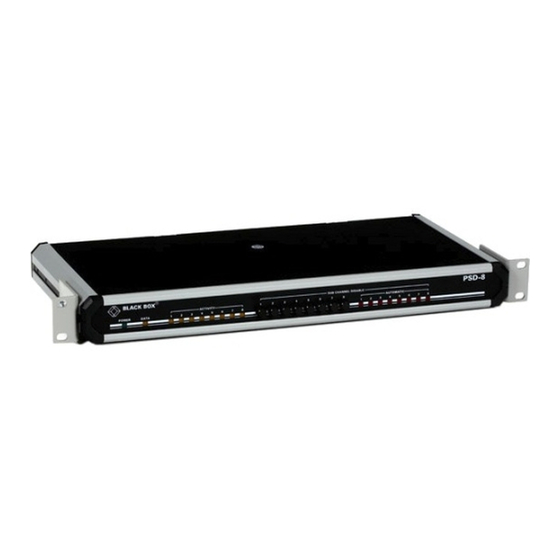
PSD-4
PSD-8
SEPTEMBER 1998
TL304A
TL305A
Advertisement
Table of Contents

Subscribe to Our Youtube Channel
Related Manuals for Black Box TL304A


Summary of Contents for Black Box TL304A
- Page 1 Order toll-free in the U.S.: Call 877-877-BBOX (outside U.S. call 724-746-5500) FREE technical support 24 hours a day, 7 days a week: Call 724-746-5500 or fax 724-746-0746 SUPPORT Mailing address: Black Box Corporation, 1000 Park Drive, Lawrence, PA 15055-1018 INFORMATION Web site: www.blackbox.com • E-mail: info@blackbox.com...
-
Page 2: Fcc Statement
FCC STATEMENT FEDERAL COMMUNICATIONS COMMISSION INDUSTRY CANADA RADIO FREQUENCY INTERFERENCE STATEMENTS This equipment generates, uses, and can radiate radio-frequency energy, and if not installed and used properly, that is, in strict accordance with the manufacturer’s instructions, may cause interference to radio communication. - Page 3 PSD-4 AND PSD-8 INSTRUCCIONES DE SEGURIDAD (Normas Oficiales Mexicanas Electrical Safety Statement) 1. Todas las instrucciones de seguridad y operación deberán ser leídas antes de que el aparato eléctrico sea operado. 2. Las instrucciones de seguridad y operación deberán ser guardadas para referencia futura. 3.
-
Page 4: Trademarks Used In This Manual
TRADEMARKS TRADEMARKS USED IN THIS MANUAL AS/400 is a registered trademark of International Business Machines Corporation. Any other trademarks mentioned in this manual are acknowledged to be the property of the trademark owners. -
Page 5: Specifications
PSD-4 AND PSD-8 1. Specifications Number of Sub-Channels — PSD-4: PSD-8: Channel Configuration — Lowest Priority: Sub-channel 1 Highest Priority: PSD-4: Sub-channel 4 PSD-8: Sub-channel 8 Sub-Channel Selection — RTS/DCD on or data transitions (strap-selectable) Sub-Channel Deselection — RTS/DCD off or 16 bits of idle data (strap-selectable) Sub-Channel Dialing —... - Page 6 CHAPTER 2: Introduction 2. Introduction The Programmable Sharing Device enables up to 4 (TL304A) or 8 (TL305A) modems or terminals to share a master modem, multiplexor, or computer port in an asynchronous or synchronous multipoint environment. (Asynchronous and synchronous equipment cannot be mixed on the same PSD.) HANNEL The main channel transmits information to all sub-channels in parallel.
-
Page 7: Installation
PSD-4 AND PSD-8 3. Installation 3.1 Choosing a Site • The PSD must be installed within five feet (1.5 m) of a grounded AC outlet. • The PSD must be within 50 feet (15 m) of the equipment that will be attached to the main channel and each sub-channel. - Page 8 CHAPTER 3: Installation Table 1. Printed Circuit-Board Switch and Strap Settings Possible Factory Stap Identity Location Settings Setting Function MAIN DCE/DTE switch Determines the PSD’s Main Channel interface as either DTE (straight connection to a modem) or as DCE (straight connection to a computer or terminal).
- Page 9 PSD-4 AND PSD-8 Figure 3. The Printed Circuit Board of the PSD-4. Figure 4. The Printed Circuit Board of the PSD-8.
-
Page 10: Asynchronous Mode
CHAPTER 3: Installation 3.3 System Synchronization SYNCHRONOUS Strap the J6 jumper over the ASYNC pins. All attached equipment must be asynchronous. Turn the BIT RATE rotary switch (BRI) to the correct system speed. No other adjustments to the PSD are necessary. YNCHRONOUS Strap the J6 jumper over the SYNC pins (this is the factory-default setting). - Page 11 PSD-4 AND PSD-8 • BIT RATE rotary switch: Set BRI to the correct system speed. • EXT. BUFFER: If any of the devices connected to the sub-channels numbered 1 through 4 are set to internal clock, then switch S1 should be ON. If any of the devices connected to the sub-channels numbered 5 through 8 are set to internal clock, then switch S2 should be ON.
-
Page 12: Operation And Troubleshooting
CHAPTER 4: Operation and Troubleshooting 4. Operation and Troubleshooting 4.1 Operation Turn on the rear-panel POWER rocker switch. The front-panel POWER LED will light. The PSD operates automatically. Except for manually disabling a sub-channel, you will not need to attend to the PSD. 4.2 Changing Setting During Operation If you have to reconfigure the PSD for a different type of operation, turn off the PSD and unplug it from its AC power source before taking off the cover to change settings. - Page 13 PSD-4 AND PSD-8 110/220 VAC Selector: SCREWS: POWER: FUSE Align either 110 or 220 Loosen these screws to take Rocker switch with the arrow. off the cover of the PSD. to turn AC power on or off Figure 5. The back panels of the PSD-4 (top) and the PSD-8 (bottom).
-
Page 14: Technical Guide
CHAPTER 5: Technical Guide 5. Technical Guide 5.1 Control Signals HANNEL ONTROL IGNALS RTS (DCD) • In RTS/DCD contention mode: follows RTS (DCD) of the selected sub-channels. • In Data Contention mode: ON if one of the sub-channels RTS (DCD) is ON. On only when the CTS signals of all active sub-channels are ON. - Page 15 PSD-4 AND PSD-8 Figure 6. Main Channel DTE with Sub-Channel DCE. Figure 7. Main Channel DTE with Sub-Channel DTE.
- Page 16 CHAPTER 5: Technical Guide Figure 8. Main Channel DCE with Sub-Channel DCE. Figure 9. Main Channel DCE with Sub-Channel DTE.
- Page 17 © Copyright 1998. Black Box Corporation. All rights reserved. 1000 Park Drive • Lawrence, PA 15055-1018 • 724-746-5500 • Fax 724-746-0746...
Need help?
Do you have a question about the TL304A and is the answer not in the manual?
Questions and answers