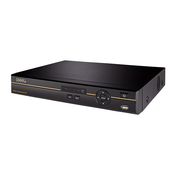
Q-See QC SERIES User Manual
Qc series h.264 network dvrs variable cif and d1 recording options
Hide thumbs
Also See for QC SERIES:
- User manual (77 pages) ,
- Setup manual (50 pages) ,
- Quick start manual (5 pages)
Table of Contents
Advertisement
Quick Links
Advertisement
Table of Contents

Related Manuals for Q-See QC SERIES


Summary of Contents for Q-See QC SERIES
- Page 1 User Manual QC SERIES H.264 NETWORK DVRs Variable CIF and D1 Recording Options...
-
Page 2: About This Manual
About this Manual This manual is written for the QC series of DVRs and was accurate at the time it was completed. However, because of our ongoing effort to constantly improve our products, Thank You for Choosing a Q-See Product! -
Page 3: Table Of Contents
3.4 Recording TABLE OF CONTENTS Manual Recording Snapshot 1. INTRODUCTION Schedule Motion, Video Loss and Camera Masking Detection Features and Specifications Video Loss Camera Masking 2. CONNECTIONS AND CONTROLS Event Response 2.1 Connections 3.5 Search and Playback QC484 Search QC448 Playback QC4316 Digital Zoom... -
Page 4: Introduction
INTRODUCTION CHAPTER 1 6.1 Alarm Input To prevent damage to your Q-See product or injury to yourself or to others, read and understand the following safety precautions in their entirety before installing or using this 6.2 Alarm Output equipment. Keep these safety instructions where all those who use the product will read them. -
Page 5: Features And Specifications
FEATURES AND SPECIFICATIONS Compression Format Your DVR (Digital Video Recorder) contains professional-grade features and flexibility that Supports one channel of combined audio and video. Independent hardware decodes the allows the do-it-yourselfer to easily setup and maintain a reliable and secure security system audio and video signal from a single channel to maintain video and audio synchronization. -
Page 6: Connections And Controls
CONNECTIONS AND CONTROLS CHAPTER 2 2.1 CONNECTIONS QC484 Rear Panel Front Panel 5 6 7 VIDEO OUT VIDEO IN AUDIO OUT AUDIO IN ALARM POWER ENTER DC 12V QC484 Number Item Function Number Item Function Video Out BNC Connector to television Alarm: Not functional on this model Video In Ports BNC Connectors for video feed from cameras (4) -
Page 7: Qc448
QC448 Front Panel Rear Panel 5 6 7 VIDEO OUT VIDEO IN AUDIO OUT AUDIO IN ALARM POWER ENTER DC 12V QC484 Number Item Function Number Item Function Video Out BNC Connector to television Alarm: Not functional on this model Video In Ports BNC Connectors for video feed from cameras (8) Net: Red light indicates that network connection is lost... -
Page 8: Qc4316
QC4316 Front Panel Rear Panel 5 6 7 VIDEO OUT VIDEO IN AUDIO OUT AUDIO IN ALARM POWER DC 12V ENTER QC484 Number Item Function Number Item Function Video Out BNC Connector to television Alarm: Not functional on this model Video In Ports BNC Connectors for video feed from cameras (16) Net: Red light indicates that network connection is lost... -
Page 9: Qc304
QC304 QC308 Front Panel Front Panel Rear Panel Rear Panel DC 12V DC 12V Number Item Function Number Item Function These show the status of the network connection, power and These show the status of the network connection, power and Status Lights hard drive respectively. -
Page 10: Qc3016
QC3016 QC524 Front Panel Front Panel Rear Panel Rear Panel DC 12V DC 12V Number Item Function Number Item Function These show the status of the network connection, power and These show the status of the network connection, power and Status Lights hard drive respectively. -
Page 11: Qc588
QC588 QC5416 Front Panel Front Panel Rear Panel Rear Panel DC 12V DC 12V Number Item Function Number Item Function These show the status of the network connection, power and These show the status of the network connection, power and Status Lights hard drive respectively. -
Page 12: Mouse Control
2.2 MOUSE CONTROL VIRTUAL KEYBOARD Whenever a menu field requires text - such as a password, new user name, or other setting This DVR can be controlled through the USB mouse, the remote control or by using the buttons on the front panel of the device. We have found that the majority of our customers - clicking on that field will bring up the virtual keyboard. -
Page 13: Remote Control
2.3 REMOTE CONTROL The buttons on the Remote Control operate in the same manner as on a conventional DVR remote. Some buttons have multiple functions depending on which menu is being accessed. Num Name Function Mult Multiple-window Switch between multiple-window and one-window view switch 0-9 number key Input password, channel or switch channel. -
Page 14: Video Display
2.4 VIDEO DISPLAY Changing Display Resolution QC-Series DVRs can use a television or a 19” or larger monitor as a main video display. You can adjust the DVR to optimize its output to best match the capabilities of your monitor or Certain models also provide the option of using a high definition display, such as an HDTV. -
Page 15: Cameras
2.5 CAMERAS CAMERA PLACEMENT CONNECTING CAMERAS When installing your camera, it is important to select a proper site not only for field of view, but for Your DVR uses BNC (British Naval Connector) ports to ensure quick and secure connections other considerations as well: for your cameras’... -
Page 16: 960H Cameras
Because your camera is weatherproof, it requires less protection than weather-resistant cameras ADDITIONAL CONSIDERATIONS and it can be placed in more exposed locations if needed. Keep in mind that most Q-See Most users prefer to operate their systems with the DVRs recording only when motion is cameras are designed to operate between 14°F to 122°F (-10°C to 50°) with a relative humidity of... -
Page 17: Basic Operation
In addition to selecting the viewing mode BASIC OPERATION CHAPTER 3 View 1 from the Shortcut Menu using the mouse, View 4 you can also cycle through the modes using This chapter is intended to get your system operational in a baseline format now that you’ve View 8 the up and down arrows on the remote or connected your system and turned it on after following the instructions on the Quick Start... -
Page 18: Shortcut Video Controls
SHORTCUT VIDEO CONTROLS 3.3 LOGIN, LOGOUT AND MAIN MENU When the mouse cursor is in the top-center portion of a channel with a live video stream, a set of shortcut controls will appear. These allow you to perform quick playback and backup LOGIN functions, digitally zoom in and add another camera. -
Page 19: Shortcut Menu
Color Setting This will open a new window COLOR SETTING IMPORTANT! It is highly recommended that you change your system allowing you to adjust how the cameras password after you log on for the first time to ensure the security of your 00:00 - 24:00 00:00 - 24:00 Period... -
Page 20: Recording
3.4 RECORDING Resolution – Depending on your model, your system will support recording and playback of video at four different resolutions: Your DVR is factory set to record when motion is detected. Most users prefer this as it means that it is easier to locate an event using the Search function (see Section 3.5) and it will take longer CIF: 352x240 pixels 2CIF (also known as HD1): 720x240 pixels... -
Page 21: Snapshot
Overlay – This window allows you to mask off areas from view. This is useful in SNAPSHOT circumstances such as when a camera’s field of view includes a combination lock or In addition to taking video of an event, the DVR can be set to record - and transmit - still other similar situation. -
Page 22: Schedule
MOTION, VIDEO LOSS AND CAMERA MASKING DETECTION SCHEDULE The Event menu is a submenu of the Setting menu and contains the Motion Detection The Schedule menu is located in the Settings menu and it allows you to determine when settings in addition to those for Video Loss and Camera Masking. Each channel can be your cameras will record and under what circumstances. -
Page 23: Video Loss
You cannot use Copy/Paste in Motion Detection because each channel will have a different The Set button will appear when either display. Right-clicking will exit the screen and your settings will be saved. Work Day or Free Day is selected in the Wed Thu Work Day Sensitivity –... -
Page 24: Search And Playback
3.5 SEARCH AND PLAYBACK Item Function The Search and Playback window can be accessed through the Shortcut menu. You can Playback Window Displays the video from one or more channels view the playback from any camera that was activated during the recording session. You are Calendar Shows dates that contain recordings also able to view the playback from multiple cameras simultaneously. -
Page 25: Search
From R/W HDD Event List Search SEARCH There are two ways to search for an event - by recording block and by starting time in the This search format allows you to easily find < 2012 > Su Mo Tu We Th Fr Sa Event List: a specific event and play it back on a single 9 10 11 12 13 14... -
Page 26: Playback
PLAYBACK Play Play Slow/Fast Volume Once you’ve selected your video(s), you can control the playback in the same manner as Forward Reverse Play Control using a VCR or computer’s media playback software. The playback interface includes features that add an extra level of control, including the ability to play in reverse as well as forward, frame-by-frame movement and multiple playback speeds. -
Page 27: Digital Zoom
DVR without being converted to .avi format using the included General Player software included on the Manuals and Software disc that came with this PICTURE 3-36 DVR or available for free download at Q-See.com by searching for your model number and looking under Software. 24hr... -
Page 28: Backup
3.6 BACKUP Once you have selected the files, press Start BACKUP to begin the download. A progress bar will be This DVR supports backing up files from the hard drive to both an external USB storage Selected Device sdb(USB DISK) Type Channel File Format... -
Page 29: Menus
4.1 MAIN MENU MENUS CHAPTER 4 The Main Menu can be accessed at any time from the Live View by right-clicking the mouse and bringing up the Short Cut Menu. Pressing the Return button on the side of the DVR will Once you’re ready to move beyond basic operation, the other menus in the system will allow you to configure the DVR to your individual needs. -
Page 30: Log
Any activity on the DVR is logged and recorded on the system. This information can You can update the firmware using this menu. Check your product’s page at www.Q-See. be viewed and searched from this window. com/Support to see if you have or need the latest version of the firmware. If your system is operating without problems, we recommend that you do not update the firmware unless there is an added feature that you need. -
Page 31: Setting Menu
4.3 SETTING MENU Pack Duration – Rather than creating 24-hour long files when a channel is set to record all SETTING the time, this allows you to set the maximum record length between one to two hours Double-clicking on the Setting icon will (measured in minutes). -
Page 32: Network
Remote Monitoring Guide included on the CD that came with your DVR or available for Enable Tour – Selecting this box will cause the screen to cycle through displaying channels download from www.Q-See.com. selected in the following fields. Interval – This is the time – from 5 to 120 seconds – that the DVR will display each group of channels before moving to the next group in the tour. -
Page 33: Advanced
4.4 ADVANCED ERROR ALERTS This window allows you to set up alarms for disk and system disconnection errors as well as The settings in this menu cover user accounts, hard disk management, video display, and how these alarms are handled. Each type of alarm can be independently enabled along with system maintenance. -
Page 34: Auto Maintenance
The Memo field allows you to include a note about the user or group that is only visible in this PAN/TILT/ZOOM CAMERAS CHAPTER 5 window. Toggling the Reusable box allows more than one user to log in using this account 5.1 CONNECTING A PTZ CAMERA Creating a group gives you the ability to set the access privileges for as many users and any The RS485 connector is used to connect and control PTZ cameras. -
Page 35: Ptz Control And Setup
5.2 PTZ CONTROL AND SETUP CONTROL Selecting the Pan/Tilt/Zoom shortcut will open the Pan/Tilt/Zoom controls window The following instructions are based on the Pelco-D protocol. You will need to have the manual for your PTZ camera at hand to ensure the proper settings within the DVR. Speed –... -
Page 36: Running Ptz Functions
RUNNING PTZ FUNCTIONS Preset Clicking on the Page Switch button in the PTZ Control Panel (Picture 5-5) will switch to a STEP 1. Start by using the eight direction arrows on the PTZ Control Panel (Picture 6-5) new window (Picture 5-11) which allows you to activate the functions created above as well to position the camera where you want. -
Page 37: Alarms
The accompanying diagram (Picture 6-2), along with your alarm’s manual should be ALARMS CHAPTER 6 consulted to ensure proper connection. This DVR features connections for external alarms – both input and output. When an event is • Normal open or Normal close type detected the system can notify local users or send notification to a monitoring service. At the • Parallel connect COM end and GND end of the alarm detector (Provide external power to same time, the system can accept signals from motion detectors, smoke detectors or other the alarm detector). -
Page 38: Alarm Output
6.2 ALARM OUTPUT 6.3 ALARM SETUP AND ACTIVATION The alarm output port should not be directly connected to a higher power load (greater than Once external alarms are properly connected, you can configure the DVR to activate them. 1A) to avoid high current which may damage the relay. Use the co-contactor to establish the SETTING connection between the alarm output port and the load. - Page 39 The bottom portion of the window allows you to choose what actions the DVR will initiate PTZ Activation – If you have Pan-Tilt-Zoom when an alarm is activated along with scheduling when the alarms are active. cameras connected to the DVR, you can cause them to be activated when an alarm occurs.
-
Page 40: Hard Disk Drive
HARD DISK DRIVE CHAPTER 7 Your DVR uses a standard computer A/V-rated SATA (Serial Advanced Technology Attachment) hard disk drive and will support up to a 3TB (terabytes) drive. These drives are the current industry standard and may be purchased wherever computer parts are sold. Depending on where you purchased your DVR, it may come with a pre-installed drive. -
Page 41: Calculating The Recording Capacity Of Ahard Disk Drive
7.2 CALCULATING THE RECORDING CAPACITY OF A APPENDIX HARD DISK DRIVE A.1 TROUBLESHOOTING While the physical data capacity of a hard drive is fixed, how much video you can record upon it depends on your recording configurations. Higher quality recordings will take up more space on the drive and setting The DVR does not boot up properly Possible Causes: the DVR to record for more frequently will fill it up more rapidly. - Page 42 Corresponding channel has no video input. Playback is not continuous when the screen 18. Forgot local menu operation password or network password is blue. a. Contact Q-See tech support and we can generate a new password for the unit. 10. Time display is not correct. Possible Causes: a. Setup is not correct Minimum required configuration of a PC for remote connection: b.
-
Page 43: Specifications
A.2 SPECIFICATIONS Parameter QC484 QC448 QC4316 Parameter QC524 QC588 QC5416 COMPRESSION Compression Standard H.264 Baseline COMPRESSION Compression Standard H.264 Baseline Format Format VIDEO Video In Composite 1.0V Composite 1.0V Composite 1.0V VIDEO Video In Composite 1.0V Composite 1.0V Composite 1.0V p-p/75Ω, p-p/75Ω, p-p/75Ω,... -
Page 44: Q-See Product Warranty
COMPRESSION Compression Standard H.264 Baseline Format Q-See is proud to back all of our products with a conditional service warranty covering all hardware for 12 months from the date of purchase. Additionally, our products also come with VIDEO Video In Composite 1.0V... -
Page 45: Questions Or Comments? Contact Us
QUESTIONS OR COMMENTS? CONTACT US PRODUCT SUPPORT, DOWNLOADS, FIRMWARE UPDATES & MANUALS 24/7 Technical Resources Live Chat (M-F, 9-5 PST) www.Q-See.com/Support Digital Peripheral Solutions, Inc. 8015 E. Crystal Drive Anaheim, CA 92807...
Need help?
Do you have a question about the QC SERIES and is the answer not in the manual?
Questions and answers