Table of Contents
Advertisement
Advertisement
Table of Contents

Related Manuals for MSI MS-7320 (V1.X)


Summary of Contents for MSI MS-7320 (V1.X)
- Page 1 P6N Diamond series MS-7320 (V1.X) Mainboard G52-73201X1...
-
Page 2: Copyright Notice
If a problem arises with your system and no solution can be obtained from the user’s manual, please contact your place of purchase or local distributor. Alternatively, please try the following help resources for further guidance. Visit the MSI website for FAQ, technical guide, BIOS updates, driver updates, and other information: http://www.msi.com.tw/program/service/faq/ faq/esc_faq_list.php... -
Page 3: Safety Instructions
Safety Instructions Always read the safety instructions carefully. Keep this User’s Manual for future reference. Keep this equipment away from humidity. Lay this equipment on a reliable flat surface before setting it up. The openings on the enclosure are for air convection hence protects the equip- ment from overheating. -
Page 4: Fcc-B Radio Frequency Interference Statement
FCC-B Radio Frequency Interference Statement T h is eq uip men t h as been tested and found to c omply with the limits for a Class B digital device, pursuant to Part 15 of the FCC Rules. These limits are designed to provide reasonable protection against harmful interference in a residential installation. -
Page 5: Weee (Waste Electrical And Electronic Equipment) Statement
WEEE (Waste Electrical and Electronic Equipment) Statement... -
Page 8: Table Of Contents
CONTENTS Copyright Notice ......................ii Trademarks ........................ii Revision History ......................ii Technical Support ......................ii Safety Instructions ......................iii FCC-B Radio Frequency Interference Statement ............iv W EEE (Waste Electrical and Electronic Equipment) Statement ........v Chapter 1 Getting Started ..................1-1 Mainboard Specifications ................... - Page 9 Appendix B nVidia RAID ..................B-1 Introduction ......................B-2 RAID Configuration ....................B-3 NVIDIA RAID Utility Installation ................B-9 RAID Drives Management .................. B-12 Appendix C nVidia System Driver ..............C-1 nVidia System Driver Installation ................ C-2 nVidia Utility Installation ..................C-5 Appendix D Dual Core Center ................
-
Page 10: Chapter 1 Getting Started
Getting Started Chapter 1 Getting Started Thank you for choosing the P6N Diamond Series (MS- 7320 V1.X) ATX Mainboard. The P6N Diamond Series ® mainboards are based on nVIDIA nForce 680i SLI & nForce 590i SLI chips ets for optimal sys tem ®... -
Page 11: Mainboard Specifications
- Core 2 Extreme (dual and quad core), Core 2 Quad, Core 2 Duo, Pentium XE & Pentium D - Supports 3/4 pin CPU Fan Pin-Header - Supports EIST Technology - Supports Hyper-Threading (HT) Technology (For the latest information about CPU, please visit http://www.msi. com.tw/cpusupport.htm) - 1333/ 1066/ 800/ 533 MHz Chipset ®... - Page 12 Getting Started Floppy - 1 floppy port - Supports 1 FDD with 360KB, 720KB, 1.2MB, 1.44MB and 2.88MB Connectors Back Panel - 1 PS/2 Mouse Port - 1 PS/2 Keyboard Port - 1 eSATA Port - 1 IEEE 1394 Port - 2 LAN Jacks - 4 USB 2.0 Ports - 5 Audio Jacks...
-
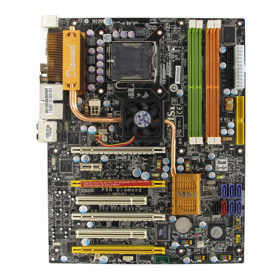
Page 13: Mainboard Layout
M S-7320 M ainboard Mainboard Layout To p: M ous e Bottom: Keyboard eSATA Port 1394 Port S/PDIF_out (coaxial) T: LAN Jack B: USB Ports T: LAN Jack nVIDIA B: USB Ports Nf6 80i SLI JPW1 T: SS -Out Line-Out M ic/Line-In CPUFAN1 T: RS-Out... -
Page 14: Packing Checklist
Getting Started Packing Checklist MSI Driver/Utility CD SLI Video Link Cable MSI motherboard Round Cable of Power Cable SATA Cable IDE Devices Round Cable of D-Bracket 2 (Optional) 1394 Bracket (Optional) Floppy Disk (Optional) external SATA Cable Back IO Shield User’s Guide... -
Page 15: Chapter 2 Hardware Setup
Hardware Setup Chapter 2 Hardware Setup This chapter provides you with the information about hardware setup procedures. While doing the installation, be careful in holding the components and follow the installation procedures. For some components, if you install in the wrong orientation, the components will not work properly. -
Page 16: Quick Components Guide
M S-7320 M ainboard Quick Components Guide CPU, p.2-3 DDR2 DIMMs, p.2-7 Back Panel JCI1, p.2-16 I/O, p.2-11 FDD1, p.2-13 ATX1, p.2-9 JPW1, p.2-9 IDE1, p.2-13 CPUFAN1, p.2-16 NBFAN1, p.2-16 JP1~2, p.2-15 PCI Express SATA1~7, Slots, p.2-23 p.2-14 JFP1~2, p.2-20 PCI Slots, p.2-26 PWRFAN1,... -
Page 17: Cpu (Central Processing Unit)
Pentium D processor in LGA 775 package. W hen you are installing the CPU, make sure to install the cooler to prevent overheating. If you do not have the CPU cooler, consult your dealer before turning on the computer. For the latest infor- mation about CPU, please visit http://www.msi.com.tw/cpusupport.htm Important Overheating Overheating will seriously damage the CPU and system. -
Page 18: Cpu & Cooler Installation
M S-7320 M ainboard CPU & Cooler Installation W hen you are installing the CPU, make sure the CPU has a cooler attached on the top to prevent overheating. Meanwhile, do not forget to apply some thermal paste on CPU before installing the heat sink/cooler fan for better heat dispersion. Follow the steps below to install the CPU &... - Page 19 Hardware Setup 5. Lift the load lever up and open the 6. After confirming the CPU direction load plate. for correct mating, put down the CPU in the socket housing frame. Be sure to grasp on the edge of the CPU base. Note that the align- ment keys are matched.
- Page 20 M S-7320 M ainboard 9. Press down the load lever lightly 10. Align the holes on the mainboard onto the load plate, and then se- with the heatsink. Push down the cure the lever with the hook under c ooler u nti l i ts f ou r c lip s g et retention tab.
-
Page 21: Memory
Hardware Setup Memory These DIMM slots are used for installing memory modules. For more information on compatible components, please visit http://www.msi.com.tw/ testreport.htm DDR2 240-pin, 1.8V 56x2=112 pin 64x2=128 pin Dual-Channel Memory Population Rules In Dual-Channel mode, the memory modules can transmit and receive data with two data bus lines simultaneously. -
Page 22: Installing Ddr2 Modules
M S-7320 M ainboard Installing DDR2 Modules 1. The memory module has only one notch on the center and will only fit in the right orientation. 2. Insert the memory module vertically into the DIMM slot. Then push it in until the golden finger on the memory module is deeply inserted in the DIMM slot. -
Page 23: Power Supply
Hardware Setup Power Supply ATX 24-Pin Power Connector: ATX1 This connector allows you to connect an ATX 24-pin power supply. To connect the ATX 24-pin power supply, make sure the plug of the pin 13 power supply is inserted in the proper orientation and the pins are aligned. -
Page 24: Important Notification About Power Issue
M S-7320 M ainboard Important Notification about Power Issue NForce chipset is very sensitive to ESD (Electrostatic Discharge), therefore this issue mostly happens while the users intensively swap memory modules under S5 (power-off) states, and the power code is plugged while installing modules. Due to several pins are very sensitive to ESD, so this kind of memory-replacement actions might cause system chipset unable to boot. -
Page 25: Back Panel
Hardware Setup Back Panel SS-Out RS-Out Mouse Line-Out CS-Out eSATA Port 1394 Port S/PDIF-Out USB Ports Mic/Line-In S/PDIF-Out Keyboard (Coaxial) (Optical) M ouse / Keyboard ® ® The standard PS/2 mouse/keyboard DIN connector is for a PS/2 mouse/keyboard. eSATA Port This eSATA (External Serial ATA) port is used to connect the external SATA device. - Page 26 M S-7320 M ainboard Audio Ports These audio connectors are used for audio devices. You can differentiate the color of the audio jacks for different audio sound effects. SS-Out (Gray) - Side-Surround Out 7.1 channel mode. RS-Out (Black) - Rear-Surround Out in 4/ 5.1/ 7.1 channel mode. Line-Out (Green) - Line Out, is a connector for speakers or headphones.
-
Page 27: Connectors
Hardware Setup Connectors Floppy Disk Drive Connector: FDD1 This connector supports 360KB, 720KB, 1.2MB, 1.44MB or 2.88MB floppy disk drive. FDD1 IDE Connector: IDE1 This connector supports IDE hard disk drives, optical disk drives and other IDE devices. IDE1 Important If you install two IDE devices on the same cable, you must configure the drives separately to master / slave mode by setting jumpers. - Page 28 M S-7320 M ainboard Serial ATA Connector: SATA1/ SATA2/ SATA3/ SATA4/ SATA5/ SATA6/ SATA7 (SATA6/ 7 is controlled by Sil4723) This connector is a high-speed Serial ATA interface port. Each connector can con- nect to one Serial ATA device. SATA4 SATA3 SATA5 SATA7 SATA6 SATA1 SATA2 Important 1.
- Page 29 Hardware Setup Hardware RAID setting Connectors: JP1, JP2 These connectors are used to set RAID mode for the hard drives that connected to SATA6, SATA7. JP1 JP2 shorting JP1 = shorting JP1 & JP2 = RAID 0 mode RAID 1 mode Important When two hard drives are installed to SATA6 and SATA7 for RAID function, the indicator LED beside the JP1 and JP2 will light in blue.
- Page 30 M S-7320 M ainboard Fan Power Connectors: CPUFAN1, NBFAN1, SYSFAN1, PWRFAN1 The fan power connectors support system cooling fan with +12V. W hen connecting the wire to the connectors, always note that the red wire is the positive and should be connected to the +12V;...
- Page 31 Hardware Setup Front Panel Audio Connector: JAUD1 This connector allows you to connect the front panel audio and is compliant with ® Intel Front Panel I/O Connectivity Design Guide. JAUD1 Pin Definition SIGNAL DESCRIPTION FP-MICIN Microphone channel Ground FP-VREFOUT Microphone Power LINE out_R Analog Port - Right channel MIC_JD...
- Page 32 M S-7320 M ainboard Front USB Connector: JUSB1 / JUSB2 / JUSB3 ® This connector, compliant with Intel I/O Connectivity Design Guide, is ideal for con- necting high-speed USB interface peripherals such as USB HDD, digital cameras, M P3 players, printers, modems and the like. Pin Definition SIGNAL SIGNAL...
- Page 33 Hardware Setup IEEE1394 Connector: J1394_1 This connector allows you to connect the IEEE1394 device via an optional IEEE1394 bracket. Pin Definition SIGNAL SIGNAL TPA+ TPA- Ground Ground TPB+ TPB- J1394_1 Cable power Cable power (The 1394 connector Key (no pin) Ground is in Green color.) IEEE1394 Bracket (Optional)
- Page 34 M S-7320 M ainboard Front Panel Connectors: JFP1, JFP2 These connectors are for electrical connection to the front panel switches and LEDs. ® The JFP1 is compliant with Intel Front Panel I/O Connectivity Design Guide. JFP1 Power Reset Switch Switch Power JFP1 Pin Definition SIGNAL...
- Page 35 Hardware Setup D-Bracket™ 2 Connector: JDB1 This connector is for you to connect to the D-Bracket™2 which integrates four LEDs and USB ports. It allows users to identify system problems through 16 various com- binations of LED signals. D-Bracket™ 2 (Optional) Connected to JDB1...
-
Page 36: Button
M S-7320 M ainboard Button This motherboard provides the following button for you to set the computer’s function. This section will explain how to change your motherboard’s function through the use of button. Clear CMOS Button: SW3 There is a CMOS RAM on board that has a power supply from external battery to keep the system configuration data. -
Page 37: Slots
Hardware Setup Slots PCI (Peripheral Component Interconnect) Express Slots The PCI Express slot supports the PCI Express interface expansion card. The PCI Express x 16 supports up to 4.0 GB/s transfer rate. The PCI Express x 8 supports up to 2.0 GB/s transfer rate. The PCI Express x 1 supports up to 250 MB/s transfer rate. -
Page 38: Nv Sli Technology
M S-7320 M ainboard NV SLI Technology NVIDIA SLI (Scalable Link Interface) technology allows two GPUs to run in tandem within a system to achieve up to twice the performance of a single graphics card. To utilize this technology, the two GPU cards must be connected by an SLI Video Link c able. - Page 39 Hardware Setup 2. After the hardware installation is completed, restart the system and install the NV SLI driver/utility. A configuration panel will be provided for Multi-GPU control. Check the Enable multi-GPU box to enable the SLI function for the onboard graphics cards (concerning the details of multi-GPU settings, please refer to your graphics card manual) .
-
Page 40: Pci Interrupt Request Routing
M S-7320 M ainboard PCI (Peripheral Component Interconnect) Slots The PCI slots support LAN cards, SCSI cards, USB cards, and other add-on cards that comply with PCI specifications. At 32 bits and 33 MHz, it yields a throughput rate of 133 MBps. 32-bit PCI Slot PCI Interrupt Request Routing The IRQ, acronym of interrupt request line and pronounced I-R-Q, are hardware lines... -
Page 41: Chapter 3 Bios Setup
BIOS Setup Chapter 3 BIOS Setup This chapter provides information on the BIOS Setup program and allows you to configure the system for optimum use. You may need to run the Setup program when: ² An error message appears on the screen during the system booting up, and requests you to run SETUP. -
Page 42: Entering Setup
M S-7320 M ainboard Entering Setup Power on the computer and the system will start POST (Power On Self Test) process. W hen the message below appears on the screen, press <DEL> key to enter Setup. Press DEL to enter SETUP If the message disappears before you respond and you still wish to enter Setup, restart the system by turning it OFF and On or pressing the RESET button. -
Page 43: Control Keys
BIOS Setup Control Keys < ↑> Move to the previous item < ↓> Move to the next item < ←> Move to the item in the left hand < →> Move to the item in the right hand <Enter> Select the item <Esc>... -
Page 44: The Main Menu
M S-7320 M ainboard The Main Menu Standard CM OS Features Use this menu for basic system configurations, such as time, date etc. Advanced BIOS Features ® Use this menu to setup the items of AMI special enhanced features. Integrated Peripherals Use this menu to specify your settings for integrated peripherals. - Page 45 BIOS Setup Load Optimized Defaults Use this menu to load the default values set by the mainboard manufacturer specifi- cally for optimal performance of the mainboard. BIOS Setting Password Use this menu to set the password for BIOS. Save & Exit Setup Save changes to CMOS and exit setup.
-
Page 46: Standard Cmos Features
M S-7320 M ainboard Standard CMOS Features The items in Standard CMOS Features Menu includes some basic setup items. Use the arrow keys to highlight the item and then use the <PgUp> or <PgDn> keys to select the value you want in each item. Date (MM:DD:YY) This allows you to set the system to the date that you want (usually the current date). - Page 47 BIOS Setup LBA/Large M ode This allows you to enable or disable the LBA Mode. Setting to Auto enables LBA mode if the device supports it and the devices is not already formatted with LBA mode disabled. DM A M ode Select DMA Mode.
-
Page 48: Advanced Bios Features
M S-7320 M ainboard Advanced BIOS Features Boot Sector Protection This function protects the BIOS from accidental corruption by unauthorized users or computer viruses. W hen enabled, the BIOS’ data cannot be changed when attempt- ing to update the BIOS with a Flash utility. To successfully update the BIOS, you’ll need to disable this Flash BIOS Protection function. - Page 49 BIOS Setup IOAPIC Function This field is used to enable or disable the APIC (Advanced Programmable Interrupt Controller). Due to compliance with PC2001 design guide, the system is able to run in APIC mode. Enabling APIC mode will expand available IRQ resources for the system. MPS Table Version This field allows you to select which MPS (Multi-Processor Specification) version to be used for the operating system.
- Page 50 M S-7320 M ainboard C55(NB) to NVIDIA(SB) Frequency This item is used to specify the frequency from north bridge to south beidge. Boot Sequence Press <Enter> to enter the sub-menu and the following screen appears: 1st/ 2nd/ 3rd Boot Device The items allow you to set the first/ second/ third boot device where BIOS attempts to load the disk operating system.
-
Page 51: Integrated Peripherals
BIOS Setup Integrated Peripherals USB Controller This setting allows you to enable/disable the onboard USB controller. USB Device Legacy Support Select [Enabled] if you need to use a USB-interfaced device in the operating system. Onboard LAN Controller This item is used to enable/disable the onboard LAN controller. Onboard 2nd LAN Controller This item is used to enable/disable the onboard 2nd LAN controller. - Page 52 M S-7320 M ainboard On-Chip ATA Devices Press <Enter> to enter the sub-menu and the following screen appears: On-Chip IDE Controller This item allows you to enable/ disable the IDE controller. PCI IDE BusMaster This item allows you to enable/ disable BIOS to used PCI busmastering for reading/ writing to IDE drives.
-
Page 53: Power Management Setup
BIOS Setup Power Management Setup Important S3-related functions described in this section are available only when your BIOS supports S3 sleep mode. ACPI Function This item is to activate the ACPI (Advanced Configuration and Power Management Interface) Function. If your operating system is ACPI-aware, such as W indows 2000/ XP, select [Enabled]. - Page 54 M S-7320 M ainboard Power Button Function This feature sets the function of the power button. Settings are: [Power Off] The power button functions as normal power off button. [Suspend] W hen you press the power button, the computer enters the suspend/sleep mode, but if the button is pressed for more than four seconds, the computer is turned off.
- Page 55 BIOS Setup Resume by Onbaord LAN W hen set to [Enabled], the feature allows your system to be awakened from the power saving modes through any event on LAN device. Resume by RTC Alarm The field is used to enable or disable the feature of booting up the system on a scheduled time/date.
-
Page 56: Pnp/Pci Configurations
M S-7320 M ainboard PNP/PCI Configurations This section describes configuring the PCI bus system and PnP (Plug & Play) feature. PCI, or Peripheral Component Interconnect, is a system which allows I/O devices to operate at speeds nearing the speed the CPU itself uses when communicating with its special components. - Page 57 BIOS Setup IRQ Resource Setup Press <Enter> to enter the sub-menu and the following screen appears. IRQ 3/4/5/7/9/10/11/14/15 These items specify the bus where the specified IRQ line is used. The settings determine if AMIBIOS should remove an IRQ from the pool of avail- able IRQs passed to devices that are configurable by the system BIOS.
-
Page 58: H/W Monitor
M S-7320 M ainboard H/W Monitor Chassis Intrusion The field enables or disables the feature of recording the chassis intrusion status and issuing a warning message if the chassis is once opened. To clear the warning message, set the field to [Reset]. The setting of the field will automatically return to [Enabled] later. -
Page 59: Cell Menu
D.O.T Control D.O.T. (Dynamic Overclocking Technology) is the automatic overclocking function, ’s newly developed CoreCell included in the MSI Technology. It is designed to detect the load balance of CPU while running programs, and to adjust the best CPU frequency automatically. W hen the motherboard detects CPU is running programs, it will speed up CPU automatically to make the program run smoothly and faster. - Page 60 M S-7320 M ainboard Important Even though the Dynamic Overclocking Technology is more stable than manual overclocking, basically, it is still risky. We suggest user to make sure that your CPU can afford to overclocking regularly first. If you find the PC appears to be unstable or reboot incidentally, it's better to disable the Dynamic Overclocking or to lower the level of overclocking options.
- Page 61 BIOS Setup M emory Timings Selects whether DRAM timing is controlled by the SPD (Serial Presence Detect) EEPROM on the DRAM module. Setting to [Auto By SPD] enables DRAM timings and the following related items to be determined by BIOS based on the configu- rations on the SPD.
- Page 62 M S-7320 M ainboard is required to guarantee that data in the write buffers can be written to the memory cells before precharge occurs. TWTR W hen the Memory Timings is set to [Manual], the field is adjustable. This item controls the W rite Data In to Read Command Delay memory timing.
-
Page 63: Load Fail-Safe/ Optimized Defaults
BIOS Setup Load Fail-Safe/ Optimized Defaults The two options on the main menu allow users to restore all of the BIOS settings to the default Fail-Safe or Optimized values. The Optimized Defaults are the default values set by the mainboard manufacturer specifically for optimal performance of the mainboard. -
Page 64: Bios Setting Password
M S-7320 M ainboard BIOS Setting Password W hen you select this function, a message as below will appear on the screen: Type the password, up to six characters in length, and press <Enter>. The password typed now will replace any previously set password from CMOS memory. You will be prompted to confirm the password. -
Page 65: Appendix A Creative Sound Blaster
Creative Sound Blaster Appendix A Creative Sound Blaster The mainboard is equipped with Creative Audio chip. It supports up to 8-channel & SPDIF audio effect and al- lows the board to attach 2, 4, 6 or 8 speakers for better surround sound effect. -
Page 66: Hardware Setup
M S-7320 M ainboard Hardware Setup Connecting the Speakers W hen you have set the Multi-Channel Audio Function mode properly in the software utility, connect your speakers to the correct phone jacks in accordance with the setting in software utility. n 2-Channel M ode for Stereo-Speaker Output Refer to the following diagram and caption for the function of each phone jack on the back panel when 2-Channel Mode is selected. - Page 67 Creative Sound Blaster n 4-Channel M ode for 4-Speaker Output 4-Channel Analog Audio Output No function Line Out (Front channels) MIC & Line-In Line Out (Rear channels) No function S/PDIF Out-Optical S/PDIF Out-Coaxial...
- Page 68 M S-7320 M ainboard n 6-Channel M ode for 6-Speaker Output 6-Channel Analog Audio Output No function Line Out (Front channels) Line Out (Rear channels) Line Out (Center and Subwoofer channel) S/PDIF Out-Optical S/PDIF Out-Coaxial...
- Page 69 Creative Sound Blaster n 8-Channel M ode for 8-Speaker Output 8-Channel Analog Audio Output Line Out (Side channels) Line Out (Front channels) Line Out (Rear channels) Line Out (Center and Subwoofer channels) S/PDIF Out-Optical S/PDIF Out-Coaxial...
-
Page 70: Installing The Creative Audio Driver
M S-7320 M ainboard Installing the Creative Audio Driver You need to install the driver for Creative CA0110 to function properly before you can get access to 2-, 4-, 6- or 8- channel and SPDIF audio operations. Follow the proce- dures described below to install the drivers for different operating systems. - Page 71 Creative Sound Blaster 3. Select the region that you needed from the scroll list . 4. Select the language that you needed from the scroll list . 5. On the next page, click Install to start the installation and follow the setup instruc- tions to complete the installation.
-
Page 72: Software Configuration
M S-7320 M ainboard Software Configuration After installing the creative audio driver, you are able to use the 2-, 4-, 6- or 8- channel and the SPDIF audio features now. Double click the creative volume control audio icon from the system tray at the lower-right corner of the screen to activate the Sound Blaster X-Fi Xtreme Audio Applications, simply click on each icon button to enter the configuration screen. - Page 73 Creative Sound Blaster Creative MediaSource Go! Launcher Click the Creative M ediaSource Go! Launcher icon to enter it’s configuraton screen. Creatvie MediaSource Go! Launcher consists of various tabs such as Programs, Product Settings, Product Support and Companion Products. In each tab, you can access different applications, called Tasks.
- Page 74 M S-7320 M ainboard SOUNDFONT BANK MANAGER ® Click the SOUNDFONT BANK MANAGER icon to enter it’s configuraton screen. W ith SoundFont Bank Manager (SFBM), you can: click on this button to get the online help information - Load SoundFont banks Replace the default sounds on your computer with the high-quality sound of a SoundFont bank.
- Page 75 Creative Sound Blaster Creative MediaSource Play/ Organizer Click the Creative MediaSource Play/ Organizer icon to enter it’s configuraton screen. Creative MediaSource Player/ Oraganizer is your digital music center for playing , creating, organizing and transferring digital music. This is your ultimate all-in-one digital entertainment software.
- Page 76 M S-7320 M ainboard Entertainment Mode Console Click the Entertainment Mode icon to enter it’s configuraton screen. Your audio device can operate in Entertainment Mode, Game Mode, where there are available. In Entertainment Mode, you audio device is optimized for movie soundtrack and music playback.
- Page 77 Creative Sound Blaster The following table explains the function of each control on the main interface. Close button - Closes the Entertainment Mode console. Minimize button - Reduce the Entertainment Mode console window. Help button - Displays information about the Entertainment Mode consloe. Select Help Contents to display the online Help.
- Page 78 M S-7320 M ainboard Speaker & Headphone Click on the speaker button to enter its configuration screen. Here you can adjust your speakers configuration. You can use it to select your type of speaker system, and to adjust the volume and cuff frequency for your subwoofer. This is the main application to use for the following tasks: - Designating the number and configuration of speakers to use =>...
- Page 79 Creative Sound Blaster X-Fi CMSS-3D Click on the X-Fi CMSS-3D button to enter its configuration screen. X-Fi CMSS-3D Creative MultiSpeaker Surround (CMSS) 3D makes ordinary two-channel (Left and Right Stereo) sound seem to surround you, even through only two speakers. For users with 5.1, 6.1, 7.1 multichannel speaker systems, CMSS can also simulate surround sound from ordinary stereo.
-
Page 80: Appendix B Nvidia Raid
nVidia RAID Appendix B nVidia RAID NVIDIA brings Redundant Array of Independent Disks (RAID) technology—which is used by the world’s lead- ing businesses—to the common PC desktop. This tech- nology uses multiple drives to either increase total disk space or to offer data protection. For all levels, RAID techniques optimize storage solutions by using multiple disks grouped together and treating them as a single storage resource. -
Page 81: Introduction
M S-7320 M ainboard Introduct ion System Requirement Operating System Support NVRAID supports the following operating systems: W indows XP/2000 & Vista RAID Arrays NVRAID supports the following types of RAID arrays described in this section: RAID 0: RAID 0 defines a disk striping scheme that improves the disk read and write times for many applications. -
Page 82: Raid Configuration
nVidia RAID RAID Configuration Basic Configuration Instructions The following are the basic steps for configuring NVRAID: Non-Bootable RAID Array 1. Choose the hard disks that are to be RAID enabled in the system BIOS. (Refer the bios section for details.) 2. - Page 83 M S-7320 M ainboard Understanding the “Define a New Array” Window Use the Define a New Array window to • Select the RAID Mode • Set up the Striping Block • Specify which disks to use for the RAID Array Depending on the platform used, the system can have one or more channels.
- Page 84 nVidia RAID Using the Define a New Array Window If necessary, press the tab key to move from field to field until the appropriate field is highlighted. • Selecting the RAID Mode By default, this is set to [Mirroring]. To change to a different RAID mode, press the down arrow key until the mode that you want appears in the RAID Mode box—either [Mirroring], [Striping], [RAID5], [Spanning], or [Stripe Mirroring].
- Page 85 M S-7320 M ainboard Completing the RAID BIOS Setup 1. After assigning your RAID array disks, press F7. The Clear disk data prompt appears. 2. Press Y if you want to wipe out all the data from the RAID array, otherwise press N.
-
Page 86: Installing The Raid Driver (For Bootable Raid Array)
Please follow the instruction below to make an nVIDIA Serial ATA RAID driver for yourself. 1. Insert the MSI CD into the CD-ROM drive. 2. Click the “Browse CD” on the Setup screen. 3. Copy all the contents in the :\\nVidia\System\C55+M CP55\IDE\Win XP\sataraid to a formatted floppy disk. - Page 87 M S-7320 M ainboard 4. Press Enter to continue with W indows XP Installation. Be sure to leave the floppy disk inserted in the floppy drive until the blue screen portion of W indows XP installation is completed, then take out the floppy. 5.
-
Page 88: Nvidia Raid Utility Installation
nVidia RAID NVIDIA RAID Utility Installation Installing the NVIDIA RAID Software Under Windows (for Non-bootable RAID Array) The existing W indows IDE Parallel ATA driver (as well as the Serial ATA driver if SATA is enabled) must be upgraded to use the NVIDIA IDE Parallel ATA driver (as well as the NV Serial ATA driver if SATA is enabled). -
Page 89: Initializing And Using The Disk Array
M S-7320 M ainboard Initializing and Using the Disk Array The RAID array is now ready to be initialized under W indows. 1. Launch Computer Management by clicking “Start” --> “Settings” --> “Control Panel” then open the “Administrative Tools” folder and double click on “Computer Management”. - Page 90 nVidia RAID 5. Check the disk in the list if you want to make the array a dynamic disk, then click Next. The Completing the Initialize and Convert Disk W izard window appears. 6. Click Finish. The “Computer Management” window appears. The actual disks listed will depend on your system, and the unallocated partition is the total combined storage of two hard disks.
-
Page 91: Raid Drives Management
M S-7320 M ainboard RAID Drives Management There is an application called NVRAIDMAN which helps you perform the following tasks of nVDIA RAID. • Viewing RAID Array Configurations View an array configuration (mirrored, striped, mirror-striped, JBOD, or any sup- ported combination) •... -
Page 92: Setting Up A Spare Raid Disk
nVidia RAID Setting Up a Spare RAID Disk You can designate a hard drive to be used as a spare drive for a RAID 1, RAID 0+1 or RAID 5 array. The spare drive can take over for a failed disk. NVRAID supports two types of spare drives: •... - Page 93 M S-7320 M ainboard Assigning a Dedicated Disk To mark a disk as dedicated, or reserve it for use by a specific array, Step 1: Mark the Disk as a Free Disk 1. Enter the system BIOS setup and make sure that the drive that you want to mark as free is RAID enabled.
- Page 94 nVidia RAID 3. Click Next. The RAID Array Selection page appears. 4. From the Free Disk Selection page, select one of the two free disks available. This would be the disk that will be designated to the mirror array. 5. Click Next. The Completing the NVIDIA Spare Disk Allocation page appears.
- Page 95 M S-7320 M ainboard Removing a Dedicated Disk Once a dedicated disk has been assigned to a particular array, it can be removed at any time. To remove the disk, right click on the dedicated disk and select “Remove Disk...” to remove it. In the previous example, simply right click on the ST380011A drive and select “Remove Disk...”.
-
Page 96: Morphing From One Raid Array To Another
nVidia RAID Morphing From One RAID Array to Another In a traditional RAID environment, when a user wants to change the current state of a disk or a current array to a new RAID configuration, the process of reconfiguring the new array involves multiple steps. The user must back up the data, delete the array, re-boot the PC, and then reconfigure the new array. -
Page 97: Hot Plug Array
M S-7320 M ainboard From New Array Disk Requirements m >= n2 m > n RAID 0 Number of RAID 0 disks must be equal to or greater than half the number of RAID 0+1 disks. RAID 1 ** Not a valid combination ** RAID 0+1 RAID 0+1 ** Not a valid combination **... -
Page 98: Initializing A Raid Array
nVidia RAID 2 Click Next and the following screen shot will appear: 3 Connect the RAID disk that you want to use with any given RAID array. 4 Click Next and the following screen shot will appear: 5 Click Finish. Initializing a RAID Array Initializing a RAID array erases all the data that is stored on that array, and writes all zeros to the disks. - Page 99 M S-7320 M ainboard 1 From the NVRAIDMAN window, right click on any available free disk and select Create Array as show in Figure below. 2 The Create Array W izard opens. Follow the W izard to create a Mirror array. 3 At the Create Array W izard Welcome screen, click Next.
- Page 100 nVidia RAID 8 Click OK. The Clearing System Data screen appears again with the Initialize Array check box checked as shown below. 9 Click Next, then click Finish at the Completing the NVIDIA Create Array W izard screen. The NVRAIDMAN windows shows the created RAID array as shown below. The Initialization Process As you can see from the screen shot above, the initialization process has started and it will be completed in a short period of time.
-
Page 101: Rebuilding A Raid Array
M S-7320 M ainboard Rebuilding a RAID Array Rebuilding is the process of restoring data to a hard drive from other drives in the array. This applies only to fault tolerant arrays such as RAID 1, RAID 0+1, as well as a RAID 5. - Page 102 nVidia RAID 4. Click Next. The Disk Selection page appears. 5. Select the drive that you want to rebuild by clicking it from the list, then click Next. The Completing the NVIDIA Rebuild Array page appears. 6. Click Finish. The array rebuilding starts after a few seconds, and a small pop-up message appears towards the bottom right corner of the screen as shown in the figure below.
- Page 103 M S-7320 M ainboard During the rebuilding process, the NVRAID Management utility screen shows the status under the System Tasks and Details sections. M ore About Rebuilding Arrays • Rebuilding Occurs in the Background The rebuilding process is very slow (it can take up to a day) and occurs in the background so as not to affect the performance of the system.
-
Page 104: Synchronizing A Raid Array
nVidia RAID Synchronizing a RAID Array Synchronizing an array will force a rebuild of redundancy or parity. The operation is applicable to any fault tolerant array such as RAID 1, 0+1 and RAID 5. • For RAID1 and RAID 0+1, “sync” results in copying the data to the redundancy disk, •... -
Page 105: Appendix C Nvidia System Driver
System Driver Appendix C nVidia System Driver MSI provides a setup CD along with your mainboard, which contains the required drivers for your system, and many other useful and powerful utility to bring you the best experience for your office professional work-... -
Page 106: Nvidia System Driver Installation
M S-7320 M ainboard nVidia System Driver Installation Click on the Driver tab and the screen below will display. NVIDIA System Driver This driver is only available for W indows 2000 and W indows XP operating system. Please follow the following step to install the driver correctly. 1. - Page 107 nVidia System Driver 2. Then the following screen displays the available components to install. All the components shown here will be selected to be installed by default. Then click Next. 3. The system will start installing the selected driver components automatically. 4.
- Page 108 M S-7320 M ainboard 5. Then the following screen displays the installation of NVIDIA IDE SW Driver. Click Yes to continue. 6. The following screen indicates that the installation is complete. Click Yes to restart your computer or click No to restart it later.
-
Page 109: Nvidia Utility Installaion
nVidia System Driver nVidia Utility Installaion 1. Click on the Utility tab and the screen below will display. 2. Then click on the NVIDIA Utility tab and the screen below will display. 3. Click the nTune Utility icon to install it. nTune Utility - provides a safe and easy way to optimize PC performance. -
Page 110: Appendix D Dual Core Center
Dual Core Center Dual CoreCenter, the most useful and powerful utility that MSI has spent muc h researc h and ef forts to develop, helps users to monitor or configure the hard- ware status of MSI Mainboard & MSI Graphics card in windows, such as CPU/GPU clock, voltage, fan speed and temperature. -
Page 111: Activating Dual Core Center
Activating Dual Core Center Once you have your Dual Core Center installed (locate the setup source file in the setup CD accompanying with your mainboard, path: Utility --> MSI Utility --> Dual Core Center), it will have an icon in the system tray, a short cut icon on the desktop, and a short cut path in your “Start-up”... -
Page 112: Main
Dual Core Center Main Before using this utility, we have to remind you: only when installing the MSI V044 (V044 has to install with the version 8.26 or newer driver)/ V046 or V060 graphics card can activate the full function of this utility. If you install a graphics card of other brand, only hardware status of the MSI mainboard would be available. - Page 113 M S-7320 M ainboard AV/ Game/ Office/ Silence/ Cool MSI provides five common settings for different environments. The settings had been set to optimal values to reac h better performanc e in eac h environment. Click the button you need.
-
Page 114: Dot(Dynamic Over Clocking
Dynamic Overclocking Technology is an automatic overclocking function, included in ’s newly developed Dual CoreCenter Technology. It is designed to detect the the MSI loading of CPU/ GPU while running programs, and to over-clock automatically. When the motherboard detects that the loading of CPU is exceed the default threshold for a time, it will speed up the CPU and fan automatically to make the system run smoother and faster. -
Page 115: Clock
M S-7320 M ainboard Clock In the Clock sub-menu, you can see clock status (including FSB/ CPU clock of mainboard and GPU/ memory clock of graphics card) of your system. And you can select desired value for overclocking. There will be several items for you to select for overclocking after you click button. -
Page 116: Voltage
Dual Core Center Voltage In the Voltage sub-menu, you can see voltage status (including Vcore, memory, GPU voltage... etc.) of your system, and you can select desired value for overclocking. It will show several items to select for overclocking after you click the button. -
Page 117: Fan Speed
M S-7320 M ainboard FAN Speed In the FAN Speed sub-menu, you can read fan status of your system. Select higher speed for better cooling effect. There are several sections for you to change the fan speed to a section after clicking button. -
Page 118: Temperature
Dual Core Center Temperature In the Temperature sub-menu, you can see temperature status of your system. On the underside, it shows the graphs of the temperatures. Only the curves of the item which the button is lit up with red color will be shown. -
Page 119: User Profile
M S-7320 M ainboard User Profile In the User Profile sub-menu, click the setting button that besides the user profile bar, and the next screen will appear. Here you can define the clock/ fan speed/ voltage by your need, click the button to choose a value quickly, or click the plus / minus sign button to... - Page 120 Dual Core Center Use the draw bar to set the max system temperature. W hen the system temperature exceeds the threshold you defined, the system will pop up a warning message and shut down the system. Use the draw bar to set the minimal fan speed. When the fan speed is lower than the threshold you defined, the system will pop up a warning message.
Need help?
Do you have a question about the MS-7320 (V1.X) and is the answer not in the manual?
Questions and answers