Table of Contents
Advertisement
Advertisement
Table of Contents

Related Manuals for MSI EFINITY Series


Summary of Contents for MSI EFINITY Series
- Page 1 EFINITY series MS-7395 (v1.X) Mainboard G52-73951X2...
-
Page 2: Trademarks
Copyright Notice T he material in this doc ument is the intellec tual property of M ICRO-STAR INTERNATIONAL. We take every care in the preparation of this document, but no guarantee is given as to the correctness of its contents. Our products are under continual improvement and we reserve the right to make changes without notice. -
Page 3: Safety Instructions
Safety Instructions Always read the safety instructions carefully. Keep this User’s Manual for future reference. Keep this equipment away from humidity. Lay this equipment on a reliable flat surface before setting it up. The openings on the enclosure are for air convection hence protects the equip- ment from overheating. -
Page 4: Fcc-B Radio Frequency Interference Statement
FCC-B Radio Frequency Interference Statement T h is eq uip men t h as been tested and found to c omply with the limits for a Class B digital device, pursuant to Part 15 of the FCC Rules. These limits are designed to provide reasonable protection against harmful interference in a residential installation. -
Page 5: Weee (Waste Electrical And Electronic Equipment) Statement
WEEE (Waste Electrical and Electronic Equipment) Statement... -
Page 8: Table Of Contents
CONTENTS Copyright Notice ......................ii Trademarks ........................ii Revision History ......................ii Technical Support ......................ii Safety Instructions ......................iii FCC-B Radio Frequency Interference Statement ............iv W EEE (Waste Electrical and Electronic Equipment) Statement ........v Chapter 1. Getting Started ..................1-1 Mainboard Specifications ................... - Page 9 DOT (Dynamic OverClocking) ................B-5 Clock ........................B-6 Voltage ......................... B-7 FAN Speed ......................B-8 Temperature ......................B-9 User Profile ......................B-10 Appendix C JM icron RAID ..................C-1 Introduction ......................C-2 JMicron RAID BIOS Utility ..................C-3 Installing Driver ....................C-11 JMicron Raid Configurer ..................
-
Page 10: Chapter 1. Getting Started
Getting Started Chapter 1 Getting Started Thank you for choosing the EFINITY Series (MS-7395 v1.X) ATX mainboard. The EFINITY Series mainboards are based on Intel ® P35 & ICH9 chipsets for optimal system efficiency. Designed to fit the advanced Intel ®... -
Page 11: Mainboard Specifications
Core 2 Quad/Core 2 Duo/Pentium/Celeron processors in the ® LGA775 package - Support Intel Yorkfield, Wolfdale ® (For the latest information about CPU, please visit http://global.msi. com .tw/index.php?func=cpuform) Supported FSB - 1333/ 1066/ 800 MHz Chipset - North Bridge: Intel P35 chipset ®... -
Page 12: Getting Started
Getting Started Connectors Back panel - 1 PS/2 mouse port - 1 PS/2 keyboard port - 1 serial port (COM1) - 1 parallel port supporting SPP/EPP/ECP mode - 4 USB 2.0 Ports - 1 LAN jack (10/100/1000) - 6 flexible audio jacks On-Board Pinheaders / Connectors - 4 USB 2.0 pinheaders - 1 CD-In connector... -
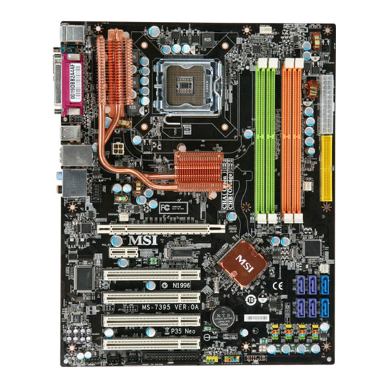
Page 13: Mainboard Layout
B:SS-Out SYSFAN1 RTL8111B PCI _E1 PCI _E2 Intel ICH9 PCI 4 Super I/O FINTEK/F7188 2FG JCI1 PCI 3 ALC888 PCI 2 BAT T JBAT1 PCI 1 CD _IN1 JAUD1 JSPD1 JTPM1(optional) JFP2 JFP1 FDD1 EFINITY Series (MS-7395 v1.X) ATX Mainboard... -
Page 14: Packing Checklist
Getting Started Packing Checklist Back IO Shield MSI Driver/Utility CD MSI motherboard Power Cable SATA Cable IDE Cable User’s Guide Floppy Cable and Quick Guide * The pictures are for reference only and may vary from the packing contents of the... -
Page 15: Chapter 2. Hardware Setup
Hardware Setup Chapter 2 Hardware Setup This chapter provides you with the information about hardware setup procedures. While doing the installation, be careful in holding the components and follow the installation procedures. For some components, if you install in the wrong orientation, the components will not work properly. -
Page 16: Quick Components Guide
M S-7395 M ainboard Quick Components Guide JCOM1, CPUFAN1, CPU, p.2-3 p.2-18 p.2-14 JPW1, DDR2, p.2-9 p.2-7 JPWR3, p.2-9 Back Panel, p.2-10 IDE1, p.2-12 SYSFAN3, SYSFAN1, p.2-14 p.2-14 JB1,JB2, p.2-19 JCI1, p.2-14 SYSFAN2, p.2-14 SATA1~6, p.2-13 JUSB1~4, Slots, p.2-18 p.2-20 JTPM1(optional), FDD1, p.2-15... -
Page 17: Cpu (Central Processing Unit)
W hen you are installing the CPU, make sure to install the cooler to prevent overheating. If you do not have the CPU cooler, consult your dealer before turning on the computer. For the latest information about CPU, please visit http://global.msi.com.tw/index.php? func=cpuform Important Overheating Overheating will seriously damage the CPU and system. - Page 18 M S-7395 M ainboard CPU & Cooler Installation W hen you are installing the CPU, make sure the CPU has a cooler attached on the top to prevent overheating. Meanwhile, do not forget to apply some thermal paste on CPU before installing the heat sink/cooler fan for better heat dispersion. Follow the steps below to install the CPU &...
- Page 19 Hardware Setup 5. Lift the load lever up and open the 6. After confirming the CPU direction load plate. for correct mating, put down the CPU in the socket housing frame. Be sure to grasp on the edge of the CPU base. Note that the align- ment keys are matched.
- Page 20 M S-7395 M ainboard 9. Press down the load lever lightly 10. Align the holes on the mainboard onto the load plate, and then se- with the heatsink. Push down the cure the lever with the hook under c ooler u nti l i ts f ou r c lip s g et retention tab.
-
Page 21: Memory
Hardware Setup Memory These DIMM slots are used for installing memory modules. For more information on compatible components, please visit http://global.msi.com. tw/index.php?func=testreport DDR2 240-pin, 1.8V 64x2=128 pin 56x2=112 pin Single-Channel: All DIMMs in GREEN Dual-Channel: Channel A in GREEN; Channel B in ORANGE... -
Page 22: Installing Memory Modules
M S-7395 M ainboard Installing Memory Modules 1. The memory module has only one notch on the center and will only fit in the right orientation. 2. Insert the memory module vertically into the DIMM slot. Then push it in until the golden finger on the memory module is deeply inserted in the DIMM slot. -
Page 23: Power Supply
Hardware Setup Power Supply ATX 24-Pin Power Connector: JPWR3 pin 13 This connector allows you to connect an ATX 24-pin power supply. To connect the ATX 24-pin power supply, make sure the plug of the power supply is inserted in the proper orientation and the pins are aligned. -
Page 24: Back Panel
M S-7395 M ainboard Back Panel RS-Out L-In Parallel Ports M ou se CS-Out Keyboard L-Out USB Ports SS-Out Serial Ports M ouse/Keyboard The standard PS/2 ® mouse/keyboard DIN connector is for a PS/2 ® mouse/keyboard. Parallel Port A parallel port is a standard printer port that supports Enhanced Parallel Port (EPP) and Extended Capabilities Parallel Port (ECP) mode. - Page 25 Hardware Setup Audio Ports These audio connectors are used for audio devices. You can differentiate the color of the audio jacks for different audio sound effects. Line-In (Blue) - Line In is used for external CD player, tapeplayer or other audio devices. Line-Out (Green) - Line Out, is a connector for speakers or headphones.
-
Page 26: Connectors
M S-7395 M ainboard Connectors Floppy Disk Drive Connector: FDD1 This connector supports 360KB, 720KB, 1.2MB, 1.44MB or 2.88MB floppy disk drive. FDD1 IDE Connector: IDE1 This connector supports IDE hard disk drives, optical disk drives and other IDE devices. IDE1 Important If you install two IDE devices on the same cable, you must configure the... - Page 27 Hardware Setup Serial ATA Connector: SATA1 ~ SATA6 This connector is a high-speed Serial ATA interface port. Each connector can connect to one Serial ATA device. SATA4 SATA2 SATA6 SATA3 SATA1 SATA5 supported by supported by Jmicroon JMB 363 Intel ICH9 Important Please do not fold the Serial ATA cable into 90-degree angle.
- Page 28 M S-7395 M ainboard Fan Power Connectors: CPUFAN1, SYSFAN1~3 The fan power connectors support system cooling fan with +12V. W hen connecting the wire to the connectors, always note that the red wire is the positive and should be connected to the +12V; the black wire is Ground and should be connected to GND. If the mainboard has a System Hardware Monitor chipset on-board, you must use a specially designed fan with speed sensor to take advantage of the CPU fan control.
- Page 29 Hardware Setup S/PDIF-Out Connector: JSPD1 This connector is used to connect S/PDIF (Sony & Philips Digital Interconnect Format) interface for digital audio transmission. JSPD1 SPDIF S/PDIF Bracket (Optional) TPM Module connector: JTPM1(optional) This connector connects to a TPM (Trusted Platform Module) module (optional). Please refer to the TPM security platform manual for more details and usages.
- Page 30 M S-7395 M ainboard Front Panel Connectors: JFP1, JFP2 These connectors are for electrical connection to the front panel switches and LEDs. The JFP1 is compliant with Intel ® Front Panel I/O Connectivity Design Guide. Power Power Switch Speaker JFP1 JFP2 Reset Power...
- Page 31 Hardware Setup Front Panel Audio Connector: JAUD1 This connector allows you to connect the front panel audio and is compliant with Intel ® Front Panel I/O Connectivity Design Guide. JAUD1 HD Audio Pin Definition SIGNAL DESCRIPTION MIC_L Microphone - Left channel Ground MIC_R Microphone - Right channel...
- Page 32 M S-7395 M ainboard Front USB Connector: JUSB1 ~ 4 These connectors, compliant with Intel ® I/O Connectivity Design Guide, is ideal for connecting high-speed USB interface peripherals such as USB HDD, digital cameras, M P3 players, printers, modems and the like. Pin Definition SIGNAL SIGNAL...
-
Page 33: Jumper
Hardware Setup Jumper The motherboard provides the following jumper for you to set the computer’s function. This section will explain how to change your motherboard’s function through the use of jumper. Hardware Overclock FSB Jumpers: JB1, JB2 (optional) You can overclock the FSB to increase the processor frequency by changing the jumpers JB1 and JB2. -
Page 34: Slots
M S-7395 M ainboard Slots PCI (Peripheral Component Interconnect) Express Slot The PCI Express slot supports the PCI Express interface expansion card. The PCI Express x 16 slot supports up to 4.0 GB/s transfer rate. The PCI Express x 1 slot supports up to 250 MB/s transfer rate. PCI Express x16 Slot PCI Express x1 Slot PCI (Peripheral Component Interconnect) Slot... -
Page 35: Chapter 3 Bios Setup
BIOS Setup Chapter 3 BIOS Setup This chapter provides information on the BIOS Setup program and allows you to configure the system for optimum use. You may need to run the Setup program when: ² An error message appears on the screen during the system booting up, and requests you to run SETUP. -
Page 36: Entering Setup
M S-7395 M ainboard Entering Setup Power on the computer and the system will start POST (Power On Self Test) process. W hen the picture below appears on the screen, press <F2> or <DEL> key to enter Setup. If the message disappears before you respond and you still wish to enter Setup, restart the system by turning it OFF and On or pressing the RESET button. - Page 37 BIOS Setup Control Keyboard M o us e Description < ↑↓> Select Item Move the cursor <Enter> Select Field Double-click the left mouse button <Esc> Jumps to the Exit menu or returns to the Click the right mouse previous from a submenu button <+>...
-
Page 38: The Language Menu
M S-7395 M ainboard The Language Menu After entering the Setup menu, the first menu you will see is the language menu. Use this menu to select the language you wish use for the BIOS setting. -
Page 39: The Main Menu
BIOS Setup The Main Menu System Status These items show the status and memory size of your system and allow you to adjust the system time, date etc. Cell M enu Use this menu to specify your settings for frequency/voltage control and overclocking. Chipset Setting Use this menu to specify your settings for chipset features. -
Page 40: System Status
M S-7395 M ainboard System Status BIOS / CPU / Memory Information These items show the BIOS, CPU status and memory size of your system (read only). System Date This allows you to set the system to the date that you want (usually the current date). The format is <day>... -
Page 41: Cell Menu
These items show the current clocks of CPU and Memory speed. Read-only. D.O.T Control This item allows users to enable/disable the D.O.T. The D.O.T. (Dynamic Overclocking Technology) is an automatic overclocking function, included in the MSI ’s newly developed Dual CoreCell Technology. - Page 42 M S-7395 M ainboard sure that your CPU can afford to overclocking regularly first. If you find the PC appears to be unstable or reboot incidentally, it's better to disable the Dynamic Overclocking or to lower the level of overclocking options. By the way, if you need to conduct overclocking manually, you also need to disable the Dynamic OverClocking first.
- Page 43 BIOS Setup Important 1. If you do not have any EMI problem, leave the setting at [Disabled] for optimal system stability and performance. But if you are plagued by EMI, select the value of Spread Spectrum for EMI reduction. 2. The greater the Spread Spectrum value is, the greater the EMI is reduced, and the system will become less stable.
-
Page 44: Chipset Setting
M S-7395 M ainboard Chipset Setting Pxe Boot Option This item is used to enable/disable the Pxe boot option. ACPI Settings Press <Enter> to enter the sub-menu. Enable ACPI Auto Configuration This item is used to enable/disable the ACPI auto configuration. Enable Hibernation This item is used to enable/disable the hibernation mode for your operation system. - Page 45 BIOS Setup hardware components turn off to save energy. The informa- tion stored in memory will be used to restore the system when a “wake up” event occurs. S3 Video Repost Selecting [Enabled] will rerun the video option ROM when system wakes up (resume) from S3 state.
- Page 46 M S-7395 M ainboard M emory Information This screen displays the current system memory capacity. DRAM Remapping Above 4G Ensure your operating system is 64bit, when set to [Enabled], the feature allows your system identify more the 4GB memory. When set to [Disabled], you can use only a maximum of 4GB.
- Page 47 BIOS Setup South Bridge Press <Enter> to enter the sub-menu. Onboard LAN Controller This item is used to enable/disable the onboard LAN controller. Azalia HD Audio This setting is used to enable/disable the onboard audio controller. High Precision Timer The HPET (High Precision Event Timers) is a component that is part of the chipset. You can to enable it, and will provide you with the means to get to it via the various ACPI methods.
- Page 48 M S-7395 M ainboard M odule Version This item shows the version of the current USB module. (read only) USB Devices This item shows the number of the USB device according type of device. Ex : show ”2 Drives,1 mouse” when you insert 2 USB flash disk and a mouse. Legacy USB Support Select [Enabled] if you need to use a USB-interfaced device in the operating system.
- Page 49 BIOS Setup Parallel Port Configuration Press <Enter> to enter the sub-menu. Parallel Port This item is used to enable/disable the parallel port. Device Settings This item shows the current setting. (read only) Change Settings Select an address and corresponding interrupt for the parallel port. Device M ode This item allows you to select the parallel port mode.
- Page 50 M S-7395 M ainboard Wake Up Event Setup Press <Enter> to enter the sub-menu. Resume By RTC Alarm The field is used to enable or disable the feature of booting up the system on a scheduled time/date. Resume By PCI Device W hen set to [Enabled], the feature allows your system to be awakened from the power saving modes through any event on PME (Power Management Event).
-
Page 51: Boot Setting
BIOS Setup Boot Setting Quiet Boot if set to [enabled] the OS boots straight to the GUI without showing the POST screen, if set to [disabled] it boots to the POST first. Setup Prompt Timeout This item allows you set the waitting time to enter the BIOS setup. Boot Option Priorities You can select the boot priorities in the Boot Option #1 and #2 items. -
Page 52: Password Setting
M S-7395 M ainboard Password Setting Security settings prevent an unauthorized person from changing any part of your system configuration. Setting Password W hen you select the Setup Administrator Password / User Password item, a password box will appear on the screen. Type the password, up to six characters in length, and press <Enter>. -
Page 53: Save & Exit
BIOS Setup Save & Exit Save Changes and Exit Use this item to save changes and exit setup. Discard Changes and Exit Use this item to abandon all changes and exit setup. Save Changes and Reset Use this item to save changes and reset the computer. Discard Changes and Reset Abandon all changes and reset the computer. -
Page 54: Appendix A Realtek Alc888 Audio
Realtek ALC888 Audio Appendix A Realtek ALC888 Audio The Realtek ALC888 provides 10-channel DAC that si- multaneously supports 7.1 sound playback and 2 chan- nels of independent s tereo s ound output (multiple streaming) through the Front-Out-Left and Front-Out- Right channels. -
Page 55: Installation For W Indows 2000/Xp
M S-7395 M ainboard Installing the Realtek HD Audio Driver You need to install the driver for Realtek ALC888 codec to function properly before you can get access to 2-, 4-, 6-, 8- channel or 7.1+2 channel audio operations. Follow the procedures described below to install the drivers for different operating systems. - Page 56 Realtek ALC888 Audio 3. Click Next to install the Realtek High Definition Audio Driver. Click here 4. Click Finish to restart the system. S el ec t t hi s option Click here...
-
Page 57: Software Configuration
M S-7395 M ainboard Software Configuration After installing the audio driver, you are able to use the 2-, 4-, 6- or 8- channel audio feature now. Click the audio icon from the system tray at the lower-right corner of the screen to activate the HD Audio Configuration. It is also available to enable the audio driver by clicking the Realtek HD Audio M anager from the Control Panel. -
Page 58: Sound Effect
Realtek ALC888 Audio Sound Effect Here you can select a sound effect you like from the Environment list. Environment Simulation You will be able to enjoy different sound experience by pulling down the arrow, totally 23 kinds of sound effect will be shown for selection. Realtek HD Audio Sound Manager also provides five popular settings “Stone Corridor”, “Bathroom”, “Sewer pipe”, “Arena”... - Page 59 M S-7395 M ainboard Equalizer Selection Equalizer frees users from default settings; users may create their owned preferred settings by utilizing this tool. 10 bands of equalizer, ranging from 100Hz to 16KHz. Save Reset The settings are saved 10 bands of equalizer permanently for future would go back to the de- fault setting...
- Page 60 Realtek ALC888 Audio Frequently Used Equalizer Setting Realtek recognizes the needs that you might have. By leveraging our long experience at audio field, Realtek HD Audio Sound Manager provides you certain optimized equal- izer settings that are frequently used for your quick enjoyment. [How to Use It] Other than the buttons “Pop”...
- Page 61 M S-7395 M ainboard Mixer In the Mixer part, you may adjust the volumes of the rear and front panels individually. 1. Adjust Volume You can adjust the volume of the speakers that you pluged in front or rear panel by select the Realtek HD Audio rear output or Realtek HD Audio front output items.
- Page 62 Realtek ALC888 Audio W hen you are playing the first audio source (for example: use W indows Media Player to play DVD/VCD), the output will be played from the rear panel, which is the default setting. Then you must to select the Realtek HD Audio front output from the scroll list first, and use a different program to play the second audio source (for example: use Winamp to play MP3 files).
-
Page 63: Playback Control
M S-7395 M ainboard 3. Playback control Playback device Tool Mute This function is to let you freely decide which ports to output the sound. And this is essential when multi- streaming playback enabled. - Realtek HD Audio Rear Output - Realtek HD Audio Front Output M u te You may choose to mute single or multiple volume controls or to completely mute... - Page 64 Realtek ALC888 Audio 4. Recording control Recording device Tool Mute -Back Line in/Mic, Front Lin in -Realtek HD Audio Input M u te You may choose to mute single or multiple volume controls or to completely mute sound input. Tool - Show the following volume controls This is to let you freely decide which volume control items to be displayed.
- Page 65 M S-7395 M ainboard Audio I/O In this tab, you can easily configure your multi-channel audio function and speakers. You can choose a desired multi-channel operation here. a. Headphone for the common headphone b. 2CH Speaker for Stereo-Speaker Output c. 4CH Speaker for 4-Speaker Output d.
- Page 66 Realtek ALC888 Audio Connector Settings Click to access connector settings. Disable front panel jack detection (option) Find no function on front panel jacks? Please check if front jacks on your system are so-called AC’97 jacks. If so, please check this item to disable front panel jack detection. M ute rear panel output when front headphone plugged in.
- Page 67 M S-7395 M ainboard S/PDIF Short for Sony/Philips Digital Interface, a standard audio file transfer format. S/PDIF allows the transfer of digital audio signals from one device to another without having to be converted first to an analog format. Maintaining the viability of a digital signal prevents the quality of the signal from degrading when it is converted to analog.
- Page 68 Realtek ALC888 Audio Test Speakers You can select the speaker by clicking it to test its functionality. The one you select will light up and make testing sound. If any speaker fails to make sound, then check whether the cable is inserted firmly to the connector or replace the bad speakers with good ones.
- Page 69 M S-7395 M ainboard Microphone In this tab you may set the function of the microphone. Select the Noise Suppres- sion to remove the possible noise during recording, or select Acoustic Echo Can- cellation to cancel the acoustic echo druing recording. Acoustic Echo Cancellation prevents playback sound from being recorded by microphone together with your sound.
-
Page 70: Audio Demo
Realtek ALC888 Audio 3D Audio Demo In this tab you may adjust your 3D positional audio before playing 3D audio applica- tions like gaming. You may also select different environment to choose the most suitable environment you like. A-17... - Page 71 M S-7395 M ainboard Information In this tab it provides some information about this HD Audio Configuration utility, including Audio Driver Version, DirectX Version, Audio Controller & Audio Codec. You may also select the language of this utility by choosing from the Language list. Also there is a selection Show icon in system tray.
-
Page 72: Hardware Setup
Realtek ALC888 Audio Hardware Setup Connecting the Speakers W hen you have set the Multi-Channel Audio Function mode properly in the software utility, connect your speakers to the correct phone jacks in accordance with the setting in software utility. n 2-Channel M ode for Stereo-Speaker Output Refer to the following diagram and caption for the function of each phone jack on the back panel when 2-Channel Mode is selected. - Page 73 M S-7395 M ainboard n 4-Channel M ode for 4-Speaker Output 4-Channel Analog Audio Output Line In Line Out (Front channels) Line Out (Rear channels) No function No function A-20...
- Page 74 Realtek ALC888 Audio n 6-Channel M ode for 6-Speaker Output 6-Channel Analog Audio Output Line In Line Out (Front channels) Line Out (Rear channels) Line Out (Center and Subwoofer channel) No function A-21...
- Page 75 M S-7395 M ainboard n 8-Channel M ode for 8-Speaker Output 8-Channel Analog Audio Output Line In Line Out (Front channels) Line Out (Rear channels) Line Out (Center and Subwoofer channel) Line Out (Side channels) Important To enable 7.1 channel audio-out function on Vista operating system, you have to install the Realtek Audio Driver.
-
Page 76: Appendix B Dual Core Center
Dual Core Center Dual CoreCenter, the most useful and powerful utility that MSI has spent muc h researc h and ef forts to develop, helps users to monitor or configure the hard- ware status of MSI Mainboard & MSI Graphics card in windows, such as CPU/GPU clock, voltage, fan speed and temperature. -
Page 77: Activating Dual Core Center
Activating Dual Core Center Once you have your Dual Core Center installed (locate the setup source file in the setup CD accompanying with your mainboard, path: Utility --> MSI Utility --> Dual Core Center), it will have an icon in the system tray, a short cut icon on the desktop, and a short cut path in your “Start-up”... -
Page 78: Main
Dual Core Center Main Before using this utility, we have to remind you: only when installing the MSI V044 (V044 has to install with the version 8.26 or newer driver)/ V046 or V060 graphics card can activate the full function of this utility. If you install a graphics card of other brand, only hardware status of the MSI mainboard would be available. - Page 79 M S-7395 M ainboard AV/ Game/ Office/ Silence/ Cool MSI provides five common settings for different environments. The settings had been set to optimal values to reac h better performanc e in eac h environment. Click the button you need.
-
Page 80: Dot (Dynamic Overclocking
Dual Core Center DOT (Dynamic OverClocking) Dynamic Overclocking Technology is an automatic overclocking function, included in the MSI ’s newly developed Dual CoreCenter Technology. It is designed to detect the loading of CPU/ GPU while running programs, and to over-clock automatically. When... -
Page 81: Clock
M S-7395 M ainboard Clock In the Clock sub-menu, you can see clock status (including FSB/ CPU clock of mainboard and GPU/ memory clock of graphics card) of your system. And you can select desired value for overclocking. There will be several items for you to select for overclocking after you click button. -
Page 82: Voltage
Dual Core Center Voltage In the Voltage sub-menu, you can see voltage status (including Vcore, memory, GPU voltage... etc.) of your system, and you can select desired value for overclocking. It will show several items to select for overclocking after you click the button. -
Page 83: Fan Speed
M S-7395 M ainboard FAN Speed In the FAN Speed sub-menu, you can read fan status of your system. Select higher speed for better cooling effect. There are several sections for you to change the fan speed to a section after clicking button. -
Page 84: Temperature
Dual Core Center Temperature In the Temperature sub-menu, you can see temperature status of your system. On the underside, it shows the graphs of the temperatures. Only the curves of the item which the button is lit up with red color will be shown. -
Page 85: User Profile
M S-7395 M ainboard User Profile In the User Profile sub-menu, click the setting button that besides the user profile bar, and the next screen will appear. Here you can define the clock/ fan speed/ voltage by your need, click the button to choose a value quickly, or click the plus / minus sign button to... - Page 86 Dual Core Center Use the draw bar to set the max system temperature. W hen the system temperature exceeds the threshold you defined, the system will pop up a warning message and shut down the system. Use the draw bar to set the minimal fan speed. When the fan speed is lower than the threshold you defined, the system will pop up a warning message.
-
Page 87: Appendix C Jm Icron Raid
Appendix C JMicron RAID Introduction This appendix will assist users in configuring and enabling RAID functionality on platforms The JMicron RAID solution supports RAID level 0 (striping), RAID level 1 (mirroring) and J BOD (Concatenate). Important... -
Page 88: Introduction
M S-7395 M ainboard Introduction JMicron JMB363 includes SATA II and PATA Host Controller. It is one-lane PCI Express to 1/2-port SATA II and 1/2-port PATA Host Controller. JMicron JMB363 offers RAID level 0 (Striping), RAID level 1 (Mirroring and Duplexing) and JBOD (Concatenate). -
Page 89: Jmicron Raid Bios Utility
JMicron RAID JMicron RAID BIOS Utility Be sure to set RAID mode for the JMicron 36x ATA Controller in BIOS before configuring the JMicron BIOS utility. After that, save the configuration and exit. During boot up (POST), press CTRL+J to enter the JMicorn BIOS RAID utility. The RAID Utility menu screen will be displayed. -
Page 90: Creating Raid Set
M S-7395 M ainboard Creating RAID set 1. Select “Create RAID Disk Drive”. Then press <Enter>. 2. Then in the Name field, specify a RAID set name and then press the <Enter> to go to the next field. 3. Choose a 0-Striped, a 1-Mirror, or a JBOD-Concatenate combination set and then press <Enter>... - Page 91 JMicron RAID 4. In the Hard Disk Disk List menu, use <Space> key to select the disks you want to create for the RAID set, then click <Enter> key to finish selection. 5. Then select the strip value for the RAID array by using the “upper arrow” or “down arrow”...
- Page 92 M S-7395 M ainboard 6. Then select the capacity of the RAID set in the Size field. The default value is the maximum capacity of the selected disks. Then press <Enter> to the Confirm Creation field. 7. The Creation field will display a message to ask you to confirm the creation. Then press <Y>...
-
Page 93: Deleting Raid Set
JMicron RAID Deleting RAID set 1. Select “Delete RAID Disk Drive”. Then press <Enter>. 2. In the RAID Disk Driver List menu, use <Space> key to select the RAID set you want to delete. Then press <Del> key. 3. Press “Y” to accept the deletion when a deletion message is appeared. - Page 94 M S-7395 M ainboard Revert HDD to non-RAID Select Revert HDD to non-RAID and press <Enter>. In the Hard Disk Driver List menu use <Space> key to select the disks you want to revert then click <Enter> key. The following screen appears, press <Y> key to remove any RAID structures from the drives.
- Page 95 JMicron RAID Solving a Mirror Conflict A Mirror conflict occurs when both disks in a RAID 1 (Mirror) configuration are unplugged from the system in turn, then plugged in again. Since both disks contain exactly the same data, the system will be unable to determine which of the two is the source drive.
- Page 96 M S-7395 M ainboard Rebuilding a Mirror drive W hen one of the disk in a RAID 1 (Mirror) configuration is unplugged from the system, then plugged in again, a dialogue box appears to ask you to rebuild the Mirror drive. Press <Y> to confirm; otherwise, press <N>. This option allows you to rebuild the Mirror drive later and synchronize the data between two hard disks.
-
Page 97: Installing Driver
Please follow the instruction below to make an “JMicron RAID Driver” for yourself. 1. Insert the MSI CD into the CD-ROM drive. 2. Click the “Browse CD” on the Setup screen. 3. Copy all the contents in the \\IDE\JMicron\Floppy32 (for 32-bit OS) or \\IDE\JMicron\Floppy64 (for 64-bit OS) to a formatted floppy disk. - Page 98 M S-7395 M ainboard † Existing Windows Vista/XP/2000 Driver Installation 1. Insert the MSI CD into the CD-ROM drive. 2. The CD will auto-run and the setup screen will appear. 3. Under the Driver tab, click on JMicron Drivers. 4. The drivers will be automatically installed.
-
Page 99: Jmicron Raid Configurer
JMicron RAID JMicron Raid Configurer There is an application called JMRaidTool which helps you perform the following tasks of JMicron RAID. • Viewing RAID Array Configurations View an array configuration (mirrored, striped) • Creating RAID Arrays • Deleting a RAID Array •... -
Page 100: Create Raid
M S-7395 M ainboard Create RAID JMRaidTool supports the creation of RAID 0, 1, 0+1 and JBOD. 1. Left-click the “Create Raid” button. 2. A CREATE RAID W IZARD dialogue will display on the screen, following the descrip- tion of every step to complete the creation. Create RAID from Existing Disk You can combine the Existing Disk (Source disk may content OS and Data) with other HD (must be larger than source Disk) to be RAID. - Page 101 JMicron RAID Remove RAID There are two ways you can choose to remove RAID. Way 1 1. Right-click the name of the disk array you want to delete and the “Remove” menu will appear. Select the “Remove Raid” of the pop-up menu. 2.
-
Page 102: Rebuild Raid
M S-7395 M ainboard Way2 1. Left-Click the “Remove Raid” icon on the toolbar. 2. A “REMOVE RAID” wizard dialogue will display on the screen, following the de- scription of every step to complete the deletion. Rebuild RAID RAID 1 can be rebuilt while RAID 0, JBOD cannot be rebuilt. There are two ways you can choose to rebuild RAID. - Page 103 JMicron RAID 2. Select “Rebuild Raid”. 3. A “REBUILD RAID W IZARD” dialogue will display on the screen, following the description of every step to complete the rebuilding. Way 2 1. If the disk array needs to rebuild then the rebuild button will be enabling on the toolbar.
-
Page 104: Solve Mirror Conflict
M S-7395 M ainboard 2. Left-Click the “Rebuild Raid” button on the toolbar. 3. A “REBUILD RAID W IZARD” dialogue will display on the screen, following the description of every step to complete the rebuilding. Solve Mirror Conflict If the conflict occurs, it will show the “REBUILDING RAID W IZARD” dialogue to ask you if you want to rebuild RAID, following the description of every step to rebuild the RAID.
Need help?
Do you have a question about the EFINITY Series and is the answer not in the manual?
Questions and answers