HP ProLiant DL120 User Manual
G6
Hide thumbs
Also See for ProLiant DL120:
- User manual (99 pages) ,
- Quickspecs (40 pages) ,
- Specifications (33 pages)
Table of Contents
Advertisement
HP ProLiant DL120 G6 Server
User Guide
Abstract
This document is for the person who installs, administers, and troubleshoots servers and storage systems. HP assumes you are qualified in the
servicing of computer equipment and trained in recognizing hazards in products with hazardous energy levels.
Part Number: 579574-004
April 2012
Edition: 4
Advertisement
Table of Contents

Related Manuals for HP ProLiant DL120


Summary of Contents for HP ProLiant DL120
-
Page 1: User Guide
User Guide Abstract This document is for the person who installs, administers, and troubleshoots servers and storage systems. HP assumes you are qualified in the servicing of computer equipment and trained in recognizing hazards in products with hazardous energy levels. - Page 2 © Copyright 2009, 2012 Hewlett-Packard Development Company, L.P. The information contained herein is subject to change without notice. The only warranties for HP products and services are set forth in the express warranty statements accompanying such products and services. Nothing herein should be construed as constituting an additional warranty. HP shall not be liable for technical or editorial errors or omissions contained herein.
-
Page 3: Table Of Contents
Contents Component identification ....................... 6 Front panel components ..........................6 Front panel LEDs and buttons ......................... 6 SAS and SATA device numbers ........................7 Rear panel components ..........................7 Rear panel LEDs and buttons ......................... 8 PCI expansion slot definitions ........................9 System board components .......................... - Page 4 SAS hard drive LED cable option ......................... 37 Battery-backed write cache battery pack option ..................... 38 Installing the FBWC module and capacitor pack ................... 40 HP Trusted Platform Module option ......................42 Installing the Trusted Platform Module board ..................42 Retaining the recovery key/password ....................44 Enabling the Trusted Platform Module ....................
- Page 5 Introduction to software problems ...................... 83 Firmware maintenance ........................86 Contacting HP ............................88 Contacting HP technical support or an authorized reseller ..............88 Server information you need ......................88 Operating system information you need ..................... 89 Battery ............................91 Regulatory compliance notices .....................
-
Page 6: Component Identification
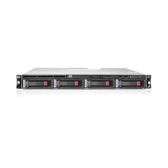
Component identification Front panel components Item Description Optical drive Serial label pull tab USB ports (2) Unit Identification (UID) button/LED Power/standby button LED Hard drive bays (4) Front panel LEDs and buttons Item Description Status Optical drive LED On = Drive is in use. Off = Drive is not active. -
Page 7: Sas And Sata Device Numbers
Item Description Status Internal health LED Green = System health is normal. Amber = System health is degraded. To identify the component in a degraded state, see "System board LEDs (on page 11)." Red = System health is critical. To identify the component in a critical state, see "System board LEDs (on page 11)."... -
Page 8: Rear Panel Leds And Buttons
Item Description Power cord connector Mouse connector 10/100/1000 NIC 1 connector/shared Lights-Out 100 management port 10/100/1000 NIC 2 connector Serial connector Slot 1 PCIe2 x16 (4, 2, 1) Slot 2 PCIe2 x16 (16, 8, 4, 1) UID button/LED Dedicated Lights-Out 100 management port Video connector USB connectors (2) USB connectors (2) -
Page 9: Pci Expansion Slot Definitions
PCI expansion slot definitions Slot Type Length Connector Interconnect PCIe2 Full Optional PCI-X Full 133 MHz/3.3 V 64 bit PCIe Half System board components Item Description DIMM slots (6) 24-pin ATX system board power connector Processor fan 1 cable connector Processor fan 2 cable connector Processor fan 3 cable connector Optical drive SATA cable connector... -
Page 10: System Maintenance Switch
Item Description Internal USB connector for tape device BMC recovery jumper BMC password reset jumper Expansion slot 1 (for riser board) Expansion slot 2 (for riser board) System maintenance switch Internal USB connector for STD USB TPM connector System battery 4-pin ATX processor power connector Processor System maintenance switch... -
Page 11: System Board Leds
• Use the Lights-Out 100 Virtual NMI feature For additional information, see the whitepaper on the HP website (http://h20000.www2.hp.com/bc/docs/support/SupportManual/c00797875/c00797875.pdf). System board LEDs Item LED description Status Processor fan failure Amber = Processor fan error Off = Normal DIMM failure Amber = DIMM has failed or is missing. -
Page 12: Fan Locations
Fan locations Battery pack LEDs Item Color Description Green System Power LED. This LED is on when the system is powered up and 12 V system power is available. This power supply is used to maintain the battery charge and provide supplementary power to the cache microcontroller. - Page 13 A fully-charged battery can normally preserve data for at least 2 days. The battery lifetime also depends on the cache module size. For more information, see the controller QuickSpecs on the HP website (http://www.hp.com). Double flash, then...
-
Page 14: Fbwc Module Leds
FBWC module LEDs The FBWC module has two single-color LEDs (green and amber). The LEDs are duplicated on the reverse side of the cache module to facilitate status viewing. 1 Green LED 2 Amber LED Interpretation A backup is in progress. A restore is in progress. -
Page 15: Operations
To remove the server from an HP, Compaq branded, telco, or third-party rack: Power down the server (on page 15). Disconnect all peripheral cables and power cords from the server rear panel. -
Page 16: Remove The Access Panel
Place the server on a sturdy, level surface. Remove the access panel WARNING: To reduce the risk of personal injury from hot surfaces, allow the drives and the internal system components to cool before touching them. CAUTION: Do not operate the server for long periods with the access panel open or removed. Operating the server in this manner results in improper airflow and improper cooling that can lead to thermal damage. -
Page 17: Install The Pci Riser Board Assembly
CAUTION: To prevent damage to the server or expansion boards, power down the server and remove all AC power cords before removing or installing the PCI riser board assembly. Power down the server (on page 15). Remove the server from the rack (on page 15). Remove the access panel (on page 16). - Page 18 Install the PCI riser board assembly. Connect any internal cables for expansion boards. Install the access panel. Install the server into the rack. Operations 18...
-
Page 19: Setup
For more information on Care Packs, see the HP website (http://www.hp.com/hps/carepack). Rack planning resources The rack resource kit ships with all HP branded or Compaq branded 9000, 10000, and H9 series racks. For more information on the content of each resource, see the rack resource kit documentation. -
Page 20: Temperature Requirements
HP servers draw in cool air through the front door and expel warm air through the rear door. Therefore, the front and rear rack doors must be adequately ventilated to allow ambient room air to enter the cabinet, and the rear door must be adequately ventilated to allow the warm air to escape from the cabinet. -
Page 21: Power Requirements
Because of the high ground-leakage currents associated with multiple servers connected to the same power source, HP recommends the use of a PDU that is either permanently wired to the building’s branch circuit or includes a nondetachable cord that is wired to an industrial-style plug. NEMA locking-style plugs or those complying with IEC 60309 are considered suitable for this purpose. -
Page 22: Rack Warnings
This process may require you to obtain additional drivers from the support CD shipped with the server or the CD that shipped with the option. The drivers may have updates that are available on the HP website (http://www.hp.com/support). -
Page 23: Hardware Options Installation
Hardware options installation Introduction If more than one option is being installed, read the installation instructions for all the hardware options and identify similar steps to streamline the installation process. WARNING: To reduce the risk of personal injury from hot surfaces, allow the drives and the internal system components to cool before touching them. -
Page 24: Single-, Dual-, And Quad-Rank Dimms
DIMM slots in this server are identified by number and by letter. Letters identify the slots to populate for specific AMP modes. Slot numbers are reported by ROM messages during boot and for error reporting. Single-, dual-, and quad-rank DIMMs To understand and configure memory protection modes properly, an understanding of single-, dual-, and quad-rank DIMMs is helpful. -
Page 25: General Dimm Slot Population Guidelines
DIMM type R = RDIMM (registered) E = UDIMM (unbuffered with ECC) For the latest supported memory information, see the QuickSpecs on the HP website (http://www.hp.com). General DIMM slot population guidelines • The HP ProLiant DL120 G6 Server has six memory slots. -
Page 26: Installing Dimms
Remove the server from the rack (on page 15). Remove the access panel (on page 16). Remove the air baffle (on page 16). For more information, see the server installation sheet on the HP website (http://www.hp.com/go/bizsupport). Open the DIMM slot latches. -
Page 27: Removing A Hard Drive Blank
Optional storage controllers provide support for hot-plug capability and drive LEDs. Controller options are: • The embedded controller supports non-hot-plug SATA hard drives. Drive LEDs are not supported. • Optional SATA controllers support hot-plug SATA hard drives and drive LEDs. •... -
Page 28: Installing A Hot-Plug Hard Drive
Remove the hard drive. Installing a hot-plug hard drive IMPORTANT: Hot-plug capability and drive LED support are only available when a supported optional controller is installed in the server. Power down the server (on page 15). Remove the existing hard drive blank ("Removing a hard drive blank"... -
Page 29: Installing A Non-Hot-Plug Hard Drive
Install the hard drive. Installing a non-hot-plug hard drive The server supports up to four SATA hard drives with the embedded controller. The server supports up to four SAS hard drives with the following options: • Optional SAS controller • Optional SAS controller cable •... - Page 30 Using a T-10 Torx screwdriver, remove the hard drive carrier. Remove four T-10 screws from the hard drive carrier. Install the hard drive. Hardware options installation 30...
- Page 31 Install the hard drive assembly. Route and connect the hard drive data and power cables to the hard drive. For SAS and SATA device numbers, see the server installation sheet. SATA hard drive Hardware options installation 31...
- Page 32 SAS hard drive Connect the hard drive data cables: For SATA hard drives, connect the cable to the system board. For more information, see the server installation sheet. For SAS hard drives, connect the optional SAS/SATA controller cable to the optional SAS controller.
-
Page 33: Optical Drive Option
Optical drive option To install the component: Power down the server (on page 15). Remove the server from the rack (on page 15). Remove the access panel (on page 16). Remove the air baffle (on page 16). Remove the 9.5-mm optical drive blank. Retain the blank for future use. Install the 9.5-mm optical drive assembly. -
Page 34: Expansion Board Option
Using a T-15 screwdriver, secure the drive to the chassis. Connect the optical drive and power cable to the optical drive. Connect the power connector to the power supply backplane. Install the access panel. Install the server into the rack. Expansion board option To install the component: Power down the server (on page 15). - Page 35 Remove the PCI riser board assembly (on page 16). Remove the expansion slot covers. Install the expansion board. IMPORTANT: The server does not power up if the PCI riser board assembly is not seated properly. Install the PCI riser board assembly (on page 17). Connect all internal cables for expansion boards.
-
Page 36: Pci-X Riser Board Option
PCI-X riser board option To install the component: Power down the server (on page 15). Remove the server from the rack (on page 15). Remove the access panel (on page 16). Disconnect all internal cables connected to existing expansion boards. Remove the PCI riser board assembly (on page 16). -
Page 37: Storage Controller Option
Connect all internal cables for expansion boards. Install the access panel. Install the server into the rack. Storage controller option IMPORTANT: For additional installation and configuration information, refer to the documentation that ships with the option. To install the component: Power down the server (on page 15). -
Page 38: Battery-Backed Write Cache Battery Pack Option
Connect the SAS hard drive LED cable to the system board and to the SAS controller. Install the access panel. Install the server into the rack. Battery-backed write cache battery pack option CAUTION: To prevent a server malfunction or damage to the equipment, do not add or remove the battery pack while an array capacity expansion, RAID level migration, or stripe size migration is in progress. - Page 39 Install the cache module on the controller. Connect the cable to the cache module. Hardware options installation 39...
-
Page 40: Installing The Fbwc Module And Capacitor Pack
Install the battery pack. Route the cable. Install the access panel. Install the server into the rack. Installing the FBWC module and capacitor pack To install the component: CAUTION: The cache module connector does not use the industry standard DDR3 mini DIMM pinout. - Page 41 Connect the capacitor pack cable to the connector on the top of the cache module. Install the cache module. Install the capacitor pack. Hardware options installation 41...
-
Page 42: Hp Trusted Platform Module Option
Recovery Mode after BitLocker detects a possible compromise of system integrity. • HP is not liable for blocked data access caused by improper TPM use. For operating instructions, see the encryption technology feature documentation provided by the operating system. - Page 43 Power down the server (on page 15). Remove the server from the rack, if necessary ("Remove the server from the rack" on page 15). Place the server on a flat, level work surface. Remove the access panel (on page 16). Access the TPM connector.
-
Page 44: Retaining The Recovery Key/Password
OS application TPM settings. For more information on firmware updates and hardware procedures, see the HP Trusted Platform Module Best Practices White Paper on the HP website (http://www.hp.com/support). -
Page 45: Cabling
Cabling Cabling overview This section provides guidelines that help you make informed decisions about cabling the server and hardware options to optimize performance. Server cabling CAUTION: When routing cables, always be sure that the cables are not in a position where they can be pinched or air flow can be blocked. -
Page 46: Bbwc Battery Cabling To An Optional Controller
BBWC battery cabling to an optional controller Power supply (500 W) cabling Cabling 46... -
Page 47: Sata Cabling
SATA cabling SATA cabling to the SGPIO connector and the 12C cable connector Cabling 47... -
Page 48: Sas Cabling To The Sgpio Connector And The 12C Cable Connector
SAS cabling to the SGPIO connector and the 12C cable connector Internal USB cabling Cabling 48... -
Page 49: Fan Cabling
Fan cabling Cabling 49... -
Page 50: Software And Configuration Utilities
Software and configuration utilities BIOS Setup Utility To use the BIOS Setup Utility, use the following keys: • To access the BIOS Setup Utility, press the F10 key during power-up when prompted. • To navigate the menu system, use the arrow keys. •... -
Page 51: Bios Serial Console
HP website (http://www.hp.com/servers/proliant). HP Insight Diagnostics The HP Insight Diagnostics utility displays information about the server hardware and tests the system to be sure it is operating properly. The utility has online help and can be accessed using the Insight Diagnostics CD or at the HP website (http://www.hp.com/support). -
Page 52: Re-Entering The Server Serial Number
Keeping the system current Drivers HP drivers and utilities can be found on the Easy Set-up CD. For the latest drivers and information on supported operating systems, refer to the HP website (http://www.hp.com/support). IMPORTANT: Always perform a backup before installing or updating device drivers. -
Page 53: Troubleshooting
If problems continue to occur, remove and reinstall each device, checking the connectors and sockets for bent pins or other damage. Service notifications To view the latest service notifications, refer to the HP website (http://www.hp.com/go/bizsupport). Select the appropriate server model, and then click the Troubleshoot a Problem link on the product page. Firmware updates Download firmware updates from the following locations: •... -
Page 54: Dimm Handling Guidelines
• Components for option firmware updates available from the HP website (http://www.hp.com/support) HP offers a subscription service that can provide notification of firmware updates. For more information, see "Subscriber's Choice (on page 52)." For more information on updating firmware, see "Firmware maintenance (on page 86)."... -
Page 55: Problem Diagnosis
This section covers the steps to take in order to diagnose a problem quickly. To effectively troubleshoot a problem, HP recommends that you start with the first flowchart in this section, "Start diagnosis flowchart (on page 58)," and follow the appropriate diagnostic path. If the other flowcharts do not provide a troubleshooting solution, follow the diagnostic steps in "General diagnosis flowchart (on... -
Page 56: Warnings And Cautions
Warnings and cautions WARNING: Only authorized technicians trained by HP should attempt to repair this equipment. All troubleshooting and repair procedures are detailed to allow only subassembly/module-level repair. Because of the complexity of the individual boards and subassemblies, no one should attempt to make repairs at the component level or to make modifications to any printed wiring board. -
Page 57: Preparing The Server For Diagnosis
If the problem occurs randomly, what is the duration or frequency? To answer these questions, the following information may be useful: • Run HP Insight Diagnostics (on page 51) and use the survey page to view the current configuration or to compare it to previous configurations. •... -
Page 58: Start Diagnosis Flowchart
The available flowcharts include: • Start diagnosis flowchart (on page 58) • General diagnosis flowchart (on page 59) • Power-on problems flowchart (on page 61) • POST problems flowchart (on page 62) • OS boot problems flowchart (on page 64) •... -
Page 59: General Diagnosis Flowchart
"Symptom information (on page 57)" "Loose connections (on page 53)" "Service notifications (on page 53)" The most recent version of a particular server or option firmware is available on the HP website (http://www.hp.com/support). "General memory problems are occurring (on page 75)" •... - Page 60 Item • Server maintenance and service guide, located on the Easy Set-up CD or the HP website (http://www.hp.com/products/servers/platforms) • "Hardware problems (on page 66)" • "Server information you need (on page 88)" • "Operating system information you need (on page 89)"...
- Page 61 "Power source problems (on page 67)" • "Power supply problems (on page 67)" • Server maintenance and service guide, located on the Easy Set-up CD or the HP website (http://www.hp.com/products/servers/platforms) "System open circuits and short circuits (on page 77)" Troubleshooting 61...
-
Page 62: Post Problems Flowchart
POST problems flowchart Symptoms: • Server does not complete POST NOTE: The server has completed POST when the system attempts to access the boot device. • Server completes POST with errors Possible problems: • Improperly seated or faulty internal component •... - Page 63 Server maintenance and service guide, located on the Easy Set-up CD or the HP website (http://www.hp.com/products/servers/platforms) "Symptom information (on page 57)" • "Server information you need (on page 88)" • "Operating system information you need (on page 89)" "HP contact information (on page 99)" Troubleshooting 63...
-
Page 64: Os Boot Problems Flowchart
Possible causes: • Corrupted operating system • Hard drive subsystem problem Item "HP Insight Diagnostics (on page 51)" • "Operating system problems (on page 84)" • "HP contact information (on page 99)" "General memory problems are occurring (on page 75)"... -
Page 65: Server Fault Indications Flowchart
Server fault indications flowchart Symptom: Server boots, but the internal health LED or external health LED is red or amber. NOTE: For the location of server LEDs and information on their statuses, refer to the server documentation. Possible causes: • Improperly seated or faulty internal or external component •... -
Page 66: Hardware Problems
Item Server maintenance and service guide, located on the Easy Set-up CD or the HP website (http://www.hp.com/products/servers/platforms) "Power-on problems flowchart (on page 61)" "HP Insight Diagnostics (on page 51)" • "Hardware problems (on page 66)" • Server maintenance and service guide, located on the Easy Set-up CD or the HP website (http://www.hp.com/products/servers/platforms) -
Page 67: Power Problems
If Enclosure Dynamic Power Capping or Enclosure Power Limit is enabled on supported servers, be sure there is sufficient power allocation to support the server. For more information, see the following documents: The HP Power Capping and HP Dynamic Power Capping for ProLiant servers technology brief on the HP website (http://h20000.www2.hp.com/bc/docs/support/SupportManual/c01549455/c01549455.p The HP BladeSystem Onboard Administrator User Guide on the HP website (http://www.hp.com/go/bladesystem/documentation) -
Page 68: General Hardware Problems
UPS problems UPS is not working properly Action: Be sure the UPS batteries are charged to the proper level for operation. See the UPS documentation for details. Be sure the UPS power switch is in the On position. See the UPS documentation for the location of the switch. -
Page 69: Problems With New Hardware
Remove unsupported hardware. Refer to the release notes included with the hardware to be sure the problem is not caused by a last minute change to the hardware release. If no documentation is available, refer to the HP support website (http://www.hp.com/support). - Page 70 If the video does not work, refer to "Video problems (on page 78)." CAUTION: Only authorized technicians trained by HP should attempt to remove the system board. If you believe the system board requires replacement, contact HP Technical Support ("HP contact information"...
-
Page 71: Internal System Problems
DAT drive problems Sense error codes are displayed Action: Refer to the Troubleshooting DAT Drives white paper for information on DAT drive sense error codes. Search for it on the HP website (http://www.hp.com). DAT drive error or failure occurs Action: Be sure drivers, software, and firmware are upgraded to the latest revisions. - Page 72 DAT drives require cleaning every 8 to 25 hours of use or they may fail intermittently when using marginal or bad media. Be sure you are following the proper cleaning procedures described in the device and server documentation. NOTE: New DAT tapes may contain debris that will contaminate the DAT drive read/write head.
-
Page 73: Fan Problems
• Be sure the power and signal cable connectors are not damaged. • If the drive is connected to a nonembedded controller, be sure the controller is properly seated. DLT drive does not read tape Action: • Be sure the drive is seated. •... -
Page 74: Hard Drive Problems
Action: Check the LEDs on the hard drive to be sure they indicate normal function. Refer to the server documentation or the HP website for information on hard drive LEDs. Be sure no loose connections (on page 53) exist. Remove the hard drive and be sure the configuration jumpers are set properly. -
Page 75: Memory Problems
Be sure the drive bay is not defective by installing the hard drive in another bay. Run HP Insight Diagnostics (on page 51). Then, replace failed components as indicated. When the drive is a replacement drive on an array controller, be sure that the drive is the same type and of the same or larger capacity than the original drive. -
Page 76: Processor Problems
Be sure no operating system errors are indicated. Restart the server and check to see if the error message is still displayed. Run HP Insight Diagnostics (on page 51). Then, replace failed components as indicated. Server fails to recognize existing memory Action: Reseat the memory. -
Page 77: System Open Circuits And Short Circuits
Be sure you are not mixing processor stepping, core speeds, or cache sizes if this is not supported on the server. Refer to the server documentation for more information. CAUTION: Removal of some processors and heatsinks require special considerations for replacement, while other processors and heatsinks are integrated and cannot be reused once separated. -
Page 78: External Device Problems
If you cannot determine the problem by checking the specific area, perform each of the following actions. Restart the server after each action to see if the problem has been corrected. • Reseat all I/O expansion boards. • Be sure no loose connections (on page 53) exist in the rest of the server, particularly with the cables that connect to the system board. -
Page 79: Audio Problems
Press any key, or type the password, and wait a few moments for the screen to activate to be sure the power-on password feature is not in effect. You can also tell if the power-on password is enabled if a key symbol is displayed on the screen when POST completes. -
Page 80: Modem Problems
For tower model servers, check the cable connection from the input device to the server. If a KVM switching device is in use, be sure all cables and connectors are the proper length and are supported by the switch. Refer to the switch documentation. Be sure the current drivers for the operating system are installed. - Page 81 Be sure you are in terminal mode and not MS-DOS mode. Refer to the HP website (http://www.hp.com) for a complete list of AT commands. AT commands are not visible Action: Set the echo command to On using the AT command ATE.
-
Page 82: Network Controller Problems
Be sure the controller drivers are up to date. Be sure a valid IP address is assigned to the controller and that the configuration settings are correct. Run Insight Diagnostics ("HP Insight Diagnostics" on page 51) and replace failed components as indicated. -
Page 83: Software Tools And Solutions
Another useful resource is HP Insight Diagnostics. Use this utility to gather critical system hardware and software information and to help with problem diagnosis. -
Page 84: Operating System Updates
If you do not require specific fixes from the update, it is recommended that you do not apply the updates. Some updates overwrite files specific to HP. If you decide to apply an operating system update: Perform a full system backup. -
Page 85: Linux Operating Systems
Linux—Refer to the operating system documentation for information. Linux operating systems For troubleshooting information specific to Linux operating systems, refer to the Linux for ProLiant website (http://h18000.www1.hp.com/products/servers/linux). Application software problems Software locks up Action: Check the application log and operating system log for entries indicating why the software failed. -
Page 86: Firmware Maintenance
Be sure you have the most current drivers. Firmware maintenance HP has developed technologies to help ensure that HP servers provide maximum uptime with minimal maintenance. Many of these technologies also reduce server management efforts, enabling administrators to work on issues and resolve problems without taking servers offline. -
Page 87: Current Firmware Versions
If a TPM is installed and enabled on the server, enable BitLocker™ after the firmware update is complete. For more information, see the operating system documentation. Drivers HP drivers and utilities can be found on the Easy Set-up CD. For the latest drivers and information on supported operating systems, refer to the HP website (http://www.hp.com/support). IMPORTANT: Always perform a backup before installing or updating device drivers. -
Page 88: Contacting Hp
A printed copy of the system and operating environment information and a copy of any historical data that might be relevant. If possible, obtain an electronic copy of this information to send by e-mail to a support specialist. To collect this information, run HP Insight Diagnostics (on page 51) and refer to the server documentation. -
Page 89: Operating System Information You Need
IRQ and I/O address information in text format • An updated Emergency Repair Diskette • If HP drivers are installed: Version of the drivers used List of drivers • The drive subsystem and file system information: Number and size of partitions and logical drives File system on each logical drive •... - Page 90 Contents of the following files: /var/log/messages /etc/modules.conf or etc/conf.modules /etc/lilo.conf or /etc/grub.conf /etc/fstab • If HP drivers are installed: Version of the drivers used List of drivers • A list of each third-party hardware component installed, with the firmware revisions •...
-
Page 91: Battery
Battery If the server no longer automatically displays the correct date and time, you may need to replace the battery that provides power to the real-time clock. Under normal use, battery life is 5 to 10 years. WARNING: The computer contains an internal lithium manganese dioxide, a vanadium pentoxide, or an alkaline battery pack. -
Page 92: Regulatory Compliance Notices
Regulatory compliance notices Regulatory compliance identification numbers For the purpose of regulatory compliance certifications and identification, this product has been assigned a unique regulatory model number. The regulatory model number can be found on the product nameplate label, along with all required approval markings and information. When requesting compliance information for this product, always refer to this regulatory model number. -
Page 93: Declaration Of Conformity For Products Marked With The Fcc Logo, United States Only
Hewlett-Packard Company P. O. Box 692000, Mail Stop 530113 Houston, Texas 77269-2000 • 1-800-HP-INVENT (1-800-474-6836). (For continuous quality improvement, calls may be recorded or monitored.) For questions regarding this FCC declaration, contact us by mail or telephone: • Hewlett-Packard Company P. -
Page 94: European Union Regulatory Notice
Compliance with these directives implies conformity to applicable harmonized European standards (European Norms) that are listed in the EU Declaration of Conformity issued by HP for this product or product family and available (in English only) either within the product documentation or at the following HP website (http://www.hp.eu/certificates) (type the product number in the search field). -
Page 95: Japanese Notice
This symbol on the product or on its packaging indicates that this product must not be disposed of with your other household waste. Instead, it is your responsibility to dispose of your waste equipment by handing it over to a designated collection point for the recycling of waste electrical and electronic equipment. -
Page 96: Laser Compliance
To forward them to recycling or proper disposal, use the public collection system or return them to HP, an authorized HP Partner, or their agents. For more information about battery replacement or proper disposal, contact an authorized reseller or an authorized service provider. -
Page 97: Power Cord Statement For Japan
Power cord statement for Japan Acoustics statement for Germany (Geräuschemission) Schalldruckpegel L < 70 dB(A) Zuschauerpositionen (bystander positions), Normaler Betrieb (normal operation) Nach ISO 7779:1999 (Typprüfung) Regulatory compliance notices 97... -
Page 98: Electrostatic Discharge
Electrostatic discharge Preventing electrostatic discharge To prevent damaging the system, be aware of the precautions you need to follow when setting up the system or handling parts. A discharge of static electricity from a finger or other conductor may damage system boards or other static-sensitive devices. -
Page 99: Technical Support
Active Health System log Download and have available an Active Health System log for 3 days before the failure was detected. For more information, see the HP iLO 4 User Guide or HP Intelligent Provisioning User Guide on the HP website (http://www.hp.com/go/ilo/docs). - Page 100 HP specifies in the materials shipped with a replacement CSR part whether a defective part must be returned to HP. In cases where it is required to return the defective part to HP, you must ship the defective part back to HP within a defined period of time, normally five (5) business days. The defective part must be returned with the associated documentation in the provided shipping material.
- Page 101 HP sono realizzati con numerosi componenti che possono essere riparati direttamente dal cliente (CSR, Customer Self Repair). Se in fase di diagnostica HP (o un centro di servizi o di assistenza HP) identifica il guasto come riparabile mediante un ricambio CSR, HP lo spedirà direttamente al cliente per la sostituzione.
- Page 102 Si, durante la fase de diagnóstico, HP (o los proveedores o socios de servicio de HP) identifica que una reparación puede llevarse a cabo mediante el uso de un componente CSR, HP le enviará dicho componente directamente para que realice su sustitución. Los componentes CSR se clasifican en dos categorías:...
- Page 103 HP se hará cargo de todos los gastos de envío y devolución de componentes y escogerá la empresa de transporte que se utilice para dicho servicio. Para obtener más información acerca del programa de Reparaciones del propio cliente de HP, póngase en contacto con su proveedor de servicios local.
- Page 104 Opcional – Peças cujo reparo feito pelo cliente é opcional. Essas peças também são projetadas para o reparo feito pelo cliente. No entanto, se desejar que a HP as substitua, pode haver ou não a cobrança de taxa adicional, dependendo do tipo de serviço de garantia destinado ao produto.
- Page 105 Technical support 105...
- Page 106 Technical support 106...
-
Page 107: Acronyms And Abbreviations
Acronyms and abbreviations Array Configuration Utility Advanced Memory Protection advanced technology extended BBWC battery-backed write cache BIOS Basic Input/Output System baseboard management controller digital audio tape double data rate DIMM dual inline memory module digital linear tape FBWC flash-backed write cache International Electrotechnical Commission Acronyms and abbreviations 107... - Page 108 LO100i HP Lights-Out 100 Remote Management processors non-maskable interrupt NVRAM non-volatile memory ORCA Option ROM Configuration for Arrays PCI Express Peripheral Component Interconnect Express PCIe peripheral component interconnect express PCI-X peripheral component interconnect extended power distribution unit...
- Page 109 SGPIO serial general input/output standard USB TMRA recommended ambient operating temperature trusted platform module UDIMM Unregistered Dual In-Line Memory Module unit identification universal serial bus Acronyms and abbreviations 109...
-
Page 110: Documentation Feedback
Documentation feedback HP is committed to providing documentation that meets your needs. To help us improve the documentation, send any errors, suggestions, or comments to Documentation Feedback (mailto:docsfeedback@hp.com). Include the document title and part number, version number, or the URL when submitting your feedback. -
Page 111: Index
FBWC module 14, 40 connection problems 53, 81 FCC (Federal Communications Commission) connectors 6, 7 notice 92, 93 contacting HP 88, 89, 99 FCC rating label 92 controller board, installing 37 features 6 crash dump analysis 10 Federal Communications Commission (FCC) - Page 112 84 help resources 99 operating system problems 84 HP Insight Diagnostics 51 operating systems 22, 84, 85, 89 HP Optional Installation Services 19 optical drive 6, 33 HP website 99 optimum environment 19 options installation 22, 23...
- Page 113 SAS/SATA backplane 10 SATA hard drive 54, 75 series number 92 server cabling 45 warnings 22, 56 server features and options 23 website, HP 99 service notifications 53 short circuits 77 site requirements 20 software 83 software problems 83 software troubleshooting 85...
Need help?
Do you have a question about the ProLiant DL120 and is the answer not in the manual?
Questions and answers