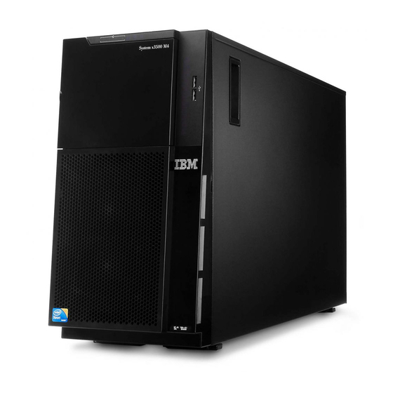
IBM System x3500 Installation And User Manual
M4 type 7383
Hide thumbs
Also See for System x3500:
- Service manual (196 pages) ,
- Installation manual (124 pages) ,
- User manual (104 pages)
Table of Contents
Advertisement
Advertisement
Table of Contents

Related Manuals for IBM System x3500


Summary of Contents for IBM System x3500
- Page 1 IBM System x3500 M4 Type 7383 Installation and User’s Guide...
- Page 3 IBM System x3500 M4 Type 7383 Installation and User’s Guide...
- Page 4 Note: Before using this information and the product it supports, read the information in Appendix B, “Notices,” on page 137, the IBM Safety Information and Environmental Notices and User Guide documents on the IBM Documentation CD, and the Warranty Information document.
-
Page 5: Table Of Contents
Instructions for IBM Business Partners ....29 How to send DSA data to IBM ....29 Server components . - Page 6 Hardware service and support ....135 IBM Taiwan product service ....135 Appendix B.
- Page 7 Trademarks......137 Important notes ......138 Particulate contamination.
- Page 8 IBM System x3500 M4 Type 7383: Installation and User’s Guide...
-
Page 9: Safety
Les sikkerhetsinformasjonen (Safety Information) før du installerer dette produktet. Antes de instalar este produto, leia as Informações sobre Segurança. Antes de instalar este producto, lea la información de seguridad. Läs säkerhetsinformationen innan du installerar den här produkten. © Copyright IBM Corp. 2012... - Page 10 Be sure to read all caution and danger statements in this document before you perform the procedures. Read any additional safety information that comes with the server or optional device before you install the device. viii IBM System x3500 M4 Type 7383: Installation and User’s Guide...
- Page 11 Attention: Use No. 26 AWG or larger UL-listed or CSA certified telecommunication line cord. Statement 1: DANGER Electrical current from power, telephone, and communication cables is hazardous. To avoid a shock hazard: v Do not connect or disconnect any cables or perform installation, maintenance, or reconfiguration of this product during an electrical storm.
- Page 12 Statement 2: CAUTION: When replacing the lithium battery, use only IBM Part Number 33F8354 or an equivalent type battery recommended by the manufacturer. If your system has a module containing a lithium battery, replace it only with the same module type made by the same manufacturer.
- Page 13 Statement 3: CAUTION: When laser products (such as CD-ROMs, DVD drives, fiber optic devices, or transmitters) are installed, note the following: v Do not remove the covers. Removing the covers of the laser product could result in exposure to hazardous laser radiation. There are no serviceable parts inside the device.
- Page 14 Statement 6: CAUTION: Do not place any objects on top of a rack-mounted device unless that rack-mounted device is intended for use as a shelf. Statement 8: IBM System x3500 M4 Type 7383: Installation and User’s Guide...
- Page 15 CAUTION: Never remove the cover on a power supply or any part that has the following label attached. Hazardous voltage, current, and energy levels are present inside any component that has this label attached. There are no serviceable parts inside these components.
- Page 16 The following label indicates moving parts nearby. Statement 26: CAUTION: Do not place any object on top of rack-mounted devices. Statement 27: CAUTION: Hazardous moving parts are nearby. Statement 35: IBM System x3500 M4 Type 7383: Installation and User’s Guide...
- Page 17 CAUTION: Hazardous energy present. Voltages with hazardous energy might cause heating when shorted with metal, which might result in splattered metall, burns, or both. Attention: This server is suitable for use on an IT power distribution system whose maximum phase-to-phase voltage is 240 V under any distribution fault condition.
- Page 18 IBM System x3500 M4 Type 7383: Installation and User’s Guide...
-
Page 19: Chapter 1. The System X3500 M4 Server
Chapter 1. The System x3500 M4 server This Installation and User's Guide contains information and instructions for setting up your IBM System x3500 M4 Type 7383 server, instructions for installing some optional devices, and instructions for cabling, and configuring the server. For... -
Page 20: The Ibm System X Documentation Cd
Note: The illustrations in this document might differ slightly from your hardware. You can download an IBM ServerGuide Setup and Installation CD to help you configure the hardware, install device drivers, and install the operating system. -
Page 21: Hardware And Software Requirements
Hardware and software requirements The IBM System x Documentation CD requires the following minimum hardware and software: v Microsoft Windows XP, Windows 2000, or Red Hat Linux v 100 MHz microprocessor v 32 MB of RAM v Adobe Acrobat Reader 3.0 (or later) or xpdf, which comes with Linux operating... -
Page 22: Related Documentation
The following documentation also comes with the server: v Environmental Notices and User Guide This document is in PDF on the IBM System x Documentation CD. It contains translated environmental notices. v IBM License Agreement for Machine Code This document is in PDF. - Page 23 Danger: These statements indicate situations that can be potentially lethal or extremely hazardous to you. A danger statement is placed just before the description of a potentially lethal or extremely hazardous procedure step or situation. Chapter 1. The System x3500 M4 server...
-
Page 24: Features And Specifications
Note: Power supplies in the server must be RDIMMs and LRDIMMs are not v Supported hard disk drives: with the same power rating or wattage. supported. – Serial Attached SCSI (SAS) – Serial ATA (SATA) IBM System x3500 M4 Type 7383: Installation and User’s Guide... - Page 25 One internal USB tape connector factors such as humidity or v One serial connector temperature might pose a risk to the server. For information about the limits for particulates and gases, see “Particulate contamination” on page 139. Chapter 1. The System x3500 M4 server...
-
Page 26: What Your Server Offers
– Event logs for ServeRAID controllers and service processors The diagnostic programs create a merged log that includes events from all collected logs. The information is collected into a file that you can send to IBM service and support. Additionally, you can view the information locally through a generated text report file. - Page 27 For additional information about DSA Preboot diagnostics, see the Problem Determination and Service Guide on the IBM System x Documentation CD v Multi-core processing ™ The server supports up to two Intel Xeon E5-2600 series multi-core microprocessors. The server comes with only one microprocessor installed.
- Page 28 Light path diagnostics provides LEDs to help you diagnose problems. For more information about the light path diagnostics, see “Light path diagnostics panel” on page 16 and the Problem Determination and Service Guide on the IBM System x Documentation CD.
-
Page 29: Reliability, Availability, And Serviceability
Microprocessor built-in self-test (BIST), internal error signal monitoring, configuration checking, and microprocessor and voltage regulator module failure identification through light path diagnostics v Memory mirrored channel support (memory mirrored channel are mutually exclusive of each other) Chapter 1. The System x3500 M4 server... -
Page 30: Ibm Systems Director
A set of common tasks that are included with IBM Systems Director provides many of the core capabilities that are required for basic management, which means instant out-of-the-box business value. -
Page 31: The Updatexpress System Packs
Updating installed plug-ins to add new features and functions to the base capabilities v Managing the life cycles of virtual resources For more information about IBM Systems Director, see the IBM Systems Director Information Center at http://publib.boulder.ibm.com/infocenter/director/v6r1x/ index.jsp?topic=/director_6.1/fqm0_main.html and the Systems Management web page at http://www.ibm.com/systems/management/, which presents an overview of... - Page 32 When this LED is lit, it indicates that the drive has failed. If an optional IBM ServeRAID controller is installed in the server, when this LED is flashing slowly (one flash per second), it indicates that the drive is being rebuilt.
-
Page 33: Operator Information Panel
System-locator LED: Use this blue LED to visually locate the server among other servers. You can use IBM Systems Director to light this LED remotely. This LED is controlled by the IMM2. When you light the system-locator LED, the LED will blink and it will continue to blink until you turn it off. -
Page 34: Light Path Diagnostics Panel
The following illustration shows the LEDs on the light path diagnostics panel. Light path diagnostics LEDs: The following table describes the LEDs on the light path diagnostics panel and suggested actions to correct the detected problems. IBM System x3500 M4 Type 7383: Installation and User’s Guide... - Page 35 Replace the hard disk drive. b. Replace the hard disk drive backplane. c. Replace the SAS controller. d. Replace the ServeRAID controller. 6. If the problem remains, go to http://www.ibm.com/systems/ support/supportsite.wss/docdisplay?brandind=5000008 &lndocid=SERV-CALL. A fan has failed, is operating too 1.
- Page 36 2. (Trained technician only) Replace the incompatible microprocessor. 3. Check the system-error logs for information about the error. Replace any component that is identified in the error log. IBM System x3500 M4 Type 7383: Installation and User’s Guide...
- Page 37 If the Memory LED and the Configuration LED are lit, check When both the Memory and the system-event logs for information about the error (see the Configuration LEDs are lit, the Problem Determination and Service Guide for more memory configuration is invalid. information). Chapter 1. The System x3500 M4 server...
- Page 38 4. If the failure remains, go to http://www.ibm.com/systems/ support/supportsite.wss/docdisplay?brandind=5000008 &lndocid=SERV-CALL. A nonmaskable interrupt has 1. Check the system-event logs for information about the occurred, or the NMI button was error. pressed. 2. Restart the server. IBM System x3500 M4 Type 7383: Installation and User’s Guide...
-
Page 39: Rear View
It allows you to blue screen the server and take a memory dump (use this button only when directed by the IBM service support). You might have to use a pen or the end of a straightened paper clip to press the button. - Page 40 Ethernet connectors: Use either of these connectors to connect the server to a network. When you enable shared Ethernet for IMM2 in the Setup utility, you can access the IMM2 using either the Ethernet 1 or the system-management Ethernet connector. IBM System x3500 M4 Type 7383: Installation and User’s Guide...
- Page 41 During typical operation, both the ac and dc power LEDs are lit. For any other combination of LEDs, see the Problem Determination and Service Guide on the IBM System x Documentation CD. v Power-supply error LED: When the power-supply error LED is lit, it indicates that the power supply has failed.
- Page 42 The following illustration shows the location of the power-supply LEDs on the rear of the server. See the Problem Determination and Service Guide for additional information about solving power-supply problems. IBM System x3500 M4 Type 7383: Installation and User’s Guide...
- Page 43 3. (Trained technician only) If the system board error LED is lit, replace the system board. Off or Faulty Replace the power supply. Flashing power-supply. Power supply is Replace the power supply. faulty but still operational Chapter 1. The System x3500 M4 server...
-
Page 44: System Pulse Leds
LED will blink slowly), and one or more fans might start running to provide cooling while the server is connected to power. You can turn on the server by pressing the power-control button. IBM System x3500 M4 Type 7383: Installation and User’s Guide... -
Page 45: Turning Off The Server
PCI options. 2. When you turn on the server with external graphical adapters installed, the IBM logo displays on the screen after approximately 3 minutes. This is normal operation while the system loads. - Page 46 The integrated management module II (IMM2) can turn off the server as an automatic response to a critical system failure. v The server turns off when the left-side cover is opened. IBM System x3500 M4 Type 7383: Installation and User’s Guide...
-
Page 47: Chapter 2. Installing Optional Devices
2. Shut down and restart the server multiple times to ensure that the server is correctly configured and functions correctly with the newly installed devices. 3. Save the DSA log as a file and send it to IBM. For information about transferring data and logs, see http://publib.boulder.ibm.com/infocenter/toolsctr/v1r0/ index.jsp?topic=/dsa/dsa_main.html. -
Page 48: Server Components
Server components The following illustration shows the major components in the server. The illustrations in this document might differ slightly from your hardware. IBM System x3500 M4 Type 7383: Installation and User’s Guide... -
Page 49: System-Board Internal Connectors
System-board internal connectors The following illustration shows the internal connectors on the system board. The following illustration shows the internal connectors on the microprocessor 2 expansion board. Chapter 2. Installing optional devices... -
Page 50: System-Board External Connectors
Note: If there is a clear protective sticker on the top of the switch blocks, you must remove and discard it to access the switches. The following table describes the functions of the SW4 switch block on the system board. IBM System x3500 M4 Type 7383: Installation and User’s Guide... - Page 51 Table 4. System board SW4 switch block definition Switch number Switch name Default position Description UEFI boot backup When this switch is off, the primary firmware ROM page is loaded. When this switch is on, the secondary (backup) firmware ROM page is loaded.
-
Page 52: System-Board Leds And Controls
LEDs. The error LEDs that were lit while the system-board tray was running will be lit again while the button is pressed. The following illustration shows the LEDs and controls on the system board. IBM System x3500 M4 Type 7383: Installation and User’s Guide... -
Page 53: Hard Disk Drive Backplane Connectors
The following illustration shows the LEDs on the microprocessor 2 expansion board. Hard disk drive backplane connectors The following illustrations show the connectors on the 2.5-inch and 3.5-inch hard disk drive backplanes and the backplate assembly. Figure 1. Connectors on the 3.5-inch hard disk drive backplane Chapter 2. - Page 54 Figure 2. Connectors on the 3.5-inch hard disk drive backplate assembly Figure 3. Connectors on the 2.5-inch hard disk drive backplane IBM System x3500 M4 Type 7383: Installation and User’s Guide...
-
Page 55: Installation Guidelines
Before you install optional devices, read the following information: v Make sure that the devices that you are installing are supported. For a list of supported optional devices for the server, see http://www.ibm.com/systems/info/ x86servers/serverproven/compat/us/. v Read the safety information that begins on page vii and the guidelines in “Working inside the server with the power on”... -
Page 56: System Reliability Guidelines
When you are finished working on the server, reinstall all safety shields, guards, labels, and ground wires. v For a list of supported optional devices for the server, see http://www.ibm.com/ servers/eserver/serverproven/compat/us/. System reliability guidelines... -
Page 57: Working Inside The Server With The Power On
Operating the server for extended periods of time (more than 30 minutes) with the server cover removed might damage server components. v You have followed the cabling instructions that come with optional adapters. v You have replaced a failed fan within 48 hours. v You have replaced a hot-swap drive within 2 minutes of removal. -
Page 58: Internal Cable Routing And Connectors
If you replace any drives, remember which cable is attached to which drive. v When you route a cable, make sure that it does not block the airflow to the rear of the drives or over the microprocessor or DIMMs. IBM System x3500 M4 Type 7383: Installation and User’s Guide... -
Page 59: Power Cable Connection
Power cable connection The following illustration shows the power cable routing and the connectors from the power paddle card to the system board and the microprocessor 2 expansion board. Operator information panel cable connection The following illustration shows the internal cable routing and connectors from the operator information panel to the system board. -
Page 60: Light Path Diagnostics Panel Cable Connection
Light path diagnostics panel cable connection The following illustration shows the internal cable routing and connectors from the light path diagnostics panel to the system board. IBM System x3500 M4 Type 7383: Installation and User’s Guide... -
Page 61: Tape Drive Cable Connection
Tape drive cable connection You can install either a USB or SATA tape drive in the server. The following illustration shows the internal cable routing and connectors for the USB tape drive. It also shows the internal power cable for the optical drives. Chapter 2. - Page 62 The following illustrations show the cable routing and connectors for the SATA tape drive. It also shows the internal power cable for the optical drives. IBM System x3500 M4 Type 7383: Installation and User’s Guide...
-
Page 63: Dvd Drive Cable Connection
DVD drive cable connection The following illustration shows the internal SATA and power cable routing and the connectors from the DVD drive to the system board. Chapter 2. Installing optional devices... -
Page 64: Hard Disk Drive Cable Connection
Review the following information before connecting power and signal cables to internal drives: 1. The following illustrations show the connectors on the 2.5-inch and 3.5-inch hard disk drive backplanes. Figure 5. Connectors on the 3.5-inch hard disk drive backplane IBM System x3500 M4 Type 7383: Installation and User’s Guide... - Page 65 Figure 6. Connectors on the 2.5-inch hard disk drive backplane Note: If the server is configured for RAID operation using a ServeRAID adapter, you might have to reconfigure your disk arrays after you install drives. See the ServeRAID adapter documentation for additional information about RAID operation and complete instructions for using the ServeRAID adapter.
- Page 66 Review the following information before connecting cables to the backplanes: 1. For server models with sixteen 2.5-inch hot-swap hard disk drives. IBM System x3500 M4 Type 7383: Installation and User’s Guide...
- Page 67 2. For server models with sixteen 2.5-inch hot-swap hard disk drives and two ServeRAID adapters. Chapter 2. Installing optional devices...
- Page 68 3. For server models with twenty-four 2.5-inch hot-swap hard disk drives. IBM System x3500 M4 Type 7383: Installation and User’s Guide...
- Page 69 4. For server models with twenty-four 2.5-inch hot-swap hard disk drives and two ServeRAID adapters. Chapter 2. Installing optional devices...
- Page 70 5. For server models with thirty-two 2.5-inch hot-swap hard disk drives. IBM System x3500 M4 Type 7383: Installation and User’s Guide...
- Page 71 6. For server models with thirty-two 2.5-inch hot-swap hard disk drives and two ServeRAID adapters. Chapter 2. Installing optional devices...
- Page 72 7. For server models with eight 3.5-inch hot-swap hard disk drives. IBM System x3500 M4 Type 7383: Installation and User’s Guide...
- Page 73 8. For server models with eight 2.5-inch hot-swap hard disk drives and eight 3.5-inch hot-swap hard disk drives. Chapter 2. Installing optional devices...
- Page 74 9. For server models with eight 3.5-inch simple-swap hard disk drives. IBM System x3500 M4 Type 7383: Installation and User’s Guide...
-
Page 75: Fan Cage Power Cable Connection
10. For server models with one 2.5-inch simple-swap hard disk drives. Fan cage power cable connection The following illustration shows the internal cable routing and connectors from the fan cage assembly to the system board. Chapter 2. Installing optional devices... -
Page 76: Left-Side Cover/Power Cut-Off Switch Assembly Cable Connection
3. Unlock the left-side cover. Note: You must unlock the left-side cover to open or remove the bezel. When you lock the left-side cover, it locks both the cover and the bezel. IBM System x3500 M4 Type 7383: Installation and User’s Guide... - Page 77 4. Open the bezel by pressing the button on the left edge of the bezel, and rotate the left side of the bezel away from the server. 5. From inside of the top section of the bezel door, slide the blue tab up to unlock the bezel media door;...
-
Page 78: Removing The Left-Side Cover
3. Carefully turn the server on its side so that it is lying flat, with the cover facing Attention: Do not allow the server to fall over. 4. Unlock and remove the left-side cover (see “Removing the left-side cover”). IBM System x3500 M4 Type 7383: Installation and User’s Guide... -
Page 79: Removing The Fan Cage Assembly
5. Remove the air baffle from the server and set it aside. Attention: For proper cooling and airflow, replace the air baffle before you turn on the server. Operating the server with the air baffle removed might damage server components when two microprocessors installed. Removing the fan cage assembly To remove the fan cage assembly, complete the following steps: 1. - Page 80 9. Rotate the fan cage release latch to the open position. The fan cage will lift up slightly when the release latch is fully open. 10. Grasp the fan cage assembly and lift it out of the server. IBM System x3500 M4 Type 7383: Installation and User’s Guide...
-
Page 81: Installing A Simple-Swap Fan
Installing a simple-swap fan The server comes with two 120 mm x 38 mm simple-swap fans in the fan cage assembly. The following instructions can be used to install any simple-swap fan in the server. Notes: 1. When you install the second microprocessor, you must also install fan 2 and the air baffle that come with the second microprocessor upgrade kit. - Page 82 8. Insert the fan into the socket and close the handle to the locked position. 9. Close the fan cage cover. 10. Install and lock the left-side cover (see “Replacing the left-side cover” on page 113). IBM System x3500 M4 Type 7383: Installation and User’s Guide...
-
Page 83: Installing Drives
If you have other devices to install or remove, do so now. Otherwise, go to “Completing the installation” on page 109. Installing drives Depending on the server model, the server might come with a SATA attached DVD-ROM drive in bay 1. The followings are illustrations of the server and the location of the drive bays. - Page 84 Figure 8. Server with sixteen 2.5-inch hard disk drives IBM System x3500 M4 Type 7383: Installation and User’s Guide...
- Page 85 Figure 9. server with twenty-four 2.5-inch hard disk drives Chapter 2. Installing optional devices...
- Page 86 Figure 10. Server with thirty-two 2.5-inch hard disk drives IBM System x3500 M4 Type 7383: Installation and User’s Guide...
- Page 87 The following illustrations show the location of the drive bays in the 3.5-inch hot-swap SAS or hot-swap SATA hard disk drive server models. Figure 11. Server with eight 3.5-inch hard disk drives Chapter 2. Installing optional devices...
-
Page 88: Installing A 2.5-Inch Hot-Swap Hard Disk Drive
PCI adapter, save the EMC shield and filler panel from the bay or the PCI adapter slot cover in the event that you later remove the drive or adapter. v For a complete list of supported options for the server, see http://www.ibm.com/ servers/eserver/serverproven/compat/us/. - Page 89 16. All the other drives will remain JBOD (the drives are presented to the operating system without a RAID configuration). v For a list of supported optional devices for the server, see http://www.ibm.com/ servers/eserver/serverproven/compat/us/. v Inspect the drive and drive bay for signs of damage.
-
Page 90: Installing A 3.5-Inch Hot-Swap Hard Disk Drive
If the server is configured for RAID operation through an optional ServeRAID adapter, you might have to reconfigure your disk arrays after you install hard disk drives. See the ServeRAID documentation on the IBM ServeRAID Support CD for additional information about RAID operation and complete instructions for using ServeRAID Manager. -
Page 91: Installing A 3.5-Inch Simple-Swap Hard Disk Drive
If the yellow LED remains lit, see the Problem Determination and Service Guide for more information. Note: You might have to reconfigure the disk arrays after you install hard disk drives. See the RAID documentation on the IBM website at http://www.ibm.com/systems/support/ for information about RAID adapters. -
Page 92: Installing A Dvd Drive
You have removed the blue optical drive rails from the side of the old drive and have them available for installation on the new drive. Note: If you are installing a drive that contains a laser, observe the following safety precautions. Statement 3: IBM System x3500 M4 Type 7383: Installation and User’s Guide... - Page 93 CAUTION: When laser products (such as CD-ROMs, DVD drives, fiber optic devices, or transmitters) are installed, note the following: v Do not remove the covers. Removing the covers of the laser product could result in exposure to hazardous laser radiation. There are no serviceable parts inside the device.
-
Page 94: Installing An Optional Tape Drive
11. Follow the instructions that come with the drive to set jumpers or switches, if there is any. Note: You might find it easier to install the new drive from the front and then attach the cables. IBM System x3500 M4 Type 7383: Installation and User’s Guide... -
Page 95: Installing A Memory Module
(SDRAM) dual inline memory modules (DIMMs) with error correcting code (ECC). See http://www.ibm.com/servers/eserver/serverproven/compat/us/ for a list of supported memory modules for the server. – The specifications of a DDR3 DIMM are on a label on the DIMM, in the following format. - Page 96 The 1.35 V UDIMMs, RDIMMs or LRDIMMs will function at 1.5 V. v The server supports a maximum of 16 dual-rank UDIMMs. The server supports up to two UDIMMs per channel. IBM System x3500 M4 Type 7383: Installation and User’s Guide...
- Page 97 v The server supports a maximum of 24 single-rank, dual-rank, or 16 quad-rank RDIMMs. The server does not support three quad-rank RDIMMs in the same channel. v The following table shows an example of the maximum amount of memory that you can install using ranked DIMMs: Table 5.
-
Page 98: Dimm Installation Sequence
1, 4, 9, 12, 2, 5, 8, 11, 10, 7, 6, 3 installed Two microprocessors 1, 13, 4, 16, 9, 21, 12, 24, 2, 14, 5, 17, 8, 20, 11, 23, 22, 10, installed 19, 7, 18, 6, 15, 3 IBM System x3500 M4 Type 7383: Installation and User’s Guide... -
Page 99: Memory Mirrored Channel
Memory mirrored channel Memory mirrored channel mode replicates and stores data on two pairs of DIMMs within two channels simultaneously. If a failure occurs, the memory controller switches from the primary pair of memory DIMMs to the backup pair of DIMMs. You can enable memory mirrored in the Setup utility (see “Starting the Setup utility”... -
Page 100: Memory Rank Sparing
Third pair of DIMMs 8, 9 Fourth pair of DIMMs 11, 12 Fifth pair of DIMMs 7, 10 Sixth pair of DIMMs 3, 6 Seventh pair of DIMMs 13, 14 IBM System x3500 M4 Type 7383: Installation and User’s Guide... -
Page 101: Installing A Dimm
Table 8. Memory rank sparing mode DIMM population sequence (continued) Number of installed Number of DIMMs microprocessor DIMM connector Eighth pair of DIMMs 16, 17 Ninth pair of DIMMs 20, 21 Tenth pair of DIMMs 23, 24 Eleventh pair of DIMMs 19, 22 Twelfth pair of DIMMs 15, 18... -
Page 102: Installing A Pci-X Bracket
6. Locate PCI slot 1 which you will install the PCI-X bracket. 7. Remove the screw that secures the expansion-slot cover. IBM System x3500 M4 Type 7383: Installation and User’s Guide... - Page 103 8. Remove the expansion-slot cover kit in PCI slot 1 and save it for future use. 9. Press the PCI-X bracket firmly into PCI slot 1. Attention: Incomplete insertion might cause damage to the system board or the adapter. 10. Make sure the latch on the side of the PCI-X bracket is secured to the rear of the server chassis.
-
Page 104: Installing An Adapter
Avoid touching the components and gold-edge connectors on the adapter. v The server uses a rotational interrupt technique to configure PCI adapters so that you can install PCI adapters that do not support sharing of PCI interrupts. IBM System x3500 M4 Type 7383: Installation and User’s Guide... - Page 105 v The following table lists the option part numbers and CRU part numbers for the network adapters. Table 9. Network adapters Network Adapters Option part CRU part Description number number NetXtreme II 1000 express Ethernet adapter 39Y6066 39Y6070 NetXtreme II 1000 express dual-port Ethernet adapter 42C1780 49Y7947 QLogic 10Gb CNA...
- Page 106 9. Remove the PCI slot filler, if installed. Keep the filler in a safe place for potential future use. IBM System x3500 M4 Type 7383: Installation and User’s Guide...
- Page 107 10. Press the adapter firmly into the expansion slot. Attention: Incomplete insertion might cause damage to the system board or the adapter. 11. Close the adapter-retention bracket. 12. Perform any configuration tasks that are required for the adapter. To install an adapter on the PCI-X bracket, complete the following steps: 1.
-
Page 108: Installing An Optional Serveraid Adapter Memory Module
Remove the ServeRAID adapter if necessary. 5. Touch the static-protective package that contains the memory card to any unpainted metal surface on the server; then, remove the memory card from the package. IBM System x3500 M4 Type 7383: Installation and User’s Guide... -
Page 109: Installing A Raid Adapter Battery Remotely In The Server
6. Align the memory module with the connector on the ServeRAID adapter and push it into the connector until it is firmly seated. If you have other devices to install or remove, do so now. Otherwise, go to “Completing the installation” on page 109. Installing a RAID adapter battery remotely in the server When you install any RAID adapter that comes with batteries, it is sometimes necessary to install the batteries in another location in the server to prevent the... - Page 110 Align the battery cable connector with the slot on the battery holder. Place the battery into the battery holder and make sure that the battery holder engages the battery securely. IBM System x3500 M4 Type 7383: Installation and User’s Guide...
-
Page 111: Installing The Microprocessor 2 Expansion Board
Note: The positioning of the remote battery depends on the type of the remote batteries that you install. b. Connect the other end of the battery cable to the battery cable connector on the battery. c. Lower and press down on the retention clip until it snaps in place to hold the battery firmly in place. - Page 112 Align the side bracket with the holes on the chassis and install the side bracket on the system board. b. Slide the side bracket toward the rear of the server. c. Fasten the thumbscrew on the side bracket. IBM System x3500 M4 Type 7383: Installation and User’s Guide...
- Page 113 8. Install the two guide pins on the system board. 9. Remove the cover on the microprocessor 2 expansion board connector from the system board. 10. Make sure the microprocessor 2 expansion board release lever is in the open position. Chapter 2.
- Page 114 12. Align the holes on the microprocessor 2 expansion board to the guide pins on the system board. Install the microprocessor 2 expansion board on the system board. IBM System x3500 M4 Type 7383: Installation and User’s Guide...
- Page 115 13. Press the microprocessor 2 expansion board firmly and horizontally to the system board. Notes: a. Static electricity that is released to internal server components when the server is powered-on might cause the server to halt, which might result in the loss of data.
-
Page 116: Installing A Second Microprocessor And Heat Sink
The following notes describe the type of microprocessor that the server supports and other information that you must consider when you install a microprocessor and heat sink: v Microprocessors are to be installed only by trained technicians. IBM System x3500 M4 Type 7383: Installation and User’s Guide... - Page 117 Do not remove the first microprocessor from the system board to install the second microprocessor. v To order an additional optional microprocessor, contact your IBM marketing representative or authorized reseller. To install an additional microprocessor and heat sink, complete the following steps: 1.
- Page 118 Open the second release lever on the microprocessor socket. c. Open the microprocessor retainer. Attention: Do not touch the connectors on the microprocessor and the microprocessor socket. 8. Install the microprocessor on the microprocessor socket: IBM System x3500 M4 Type 7383: Installation and User’s Guide...
- Page 119 a. Touch the static-protective package that contains the new microprocessor to any unpainted on the chassis or any unpainted metal surface on any other grounded rack component; then, carefully remove the microprocessor from the package. b. Release the sides of the cover and remove the cover from the installation tool.
- Page 120 Do not touch the thermal material on the bottom of the heat sink or on top of the microprocessor. Touching the thermal material will contaminate it. IBM System x3500 M4 Type 7383: Installation and User’s Guide...
- Page 121 9. Remove the microprocessor socket dust cover, tape, or label from the surface of the microprocessor socket, if one is present. Store the socket cover in a safe place. Attention: When you handle static-sensitive devices, take precautions to avoid damage from static electricity. For details about handling these devices, see “Handling static-sensitive devices”...
- Page 122 12. If you installed the second microprocessor, install the air baffle (see “Replacing the air baffle” on page 112) and fan 2 (see “Installing a simple-swap fan” on page 63). IBM System x3500 M4 Type 7383: Installation and User’s Guide...
-
Page 123: Thermal Grease
If you have other devices to install or remove, do so now. Otherwise, go to “Completing the installation” on page 109. Thermal grease The thermal grease must be replaced whenever the heat sink has been removed from the top of the microprocessor and is going to be reused or when debris is found in the grease. -
Page 124: Installing A Hot-Swap Power Supply
Before you install an additional power supply or replace a power supply with one of a different wattage, you may use the IBM Power Configurator utility to determine current system power consumption. For more information and to download the utility, go to http://www-03.ibm.com/systems/bladecenter/resources/ powerconfig.html. - Page 125 CAUTION: Never remove the cover on a power supply or any part that has the following label attached. Hazardous voltage, current, and energy levels are present inside any component that has this label attached. There are no serviceable parts inside these components.
- Page 126 9. If you are adding a power supply to the server, attach the redundant power information label that comes with this option on the server cover near the power supplies. IBM System x3500 M4 Type 7383: Installation and User’s Guide...
-
Page 127: Installing A Usb Embedded Hypervisor Flash Device
Installing a USB embedded hypervisor flash device To install a hypervisor flash device, complete the following steps: 1. Read the safety information that begins on page vii and “Installation guidelines” on page 37. 2. Turn off the server and peripheral devices and disconnect the power cords. 3. -
Page 128: Replacing The Fan Cage Assembly
8. Start the server. Confirm that it starts correctly and recognizes the newly installed devices, and make sure that no error LEDs are lit. 9. (IBM Business Partners only) Complete the additional steps in “Instructions for IBM Business Partners” on page 29. - Page 129 Chapter 2. Installing optional devices...
-
Page 130: Replacing The Air Baffle
2. Slide the air baffle down into the server until the positioning pins fit into the locating holes; then, press down on the air baffle until the pinch tab clicks into place. IBM System x3500 M4 Type 7383: Installation and User’s Guide... -
Page 131: Replacing The Left-Side Cover
Replacing the left-side cover To replace the left-side server cover, complete the following steps: 1. Make sure that all cables, adapters, and other components are installed and seated correctly and that you have not left loose tools or parts inside the server. Also, make sure that all internal cables are correctly routed. -
Page 132: Connecting The Cables
4. Lock the cover, using the key that comes with the server. Connecting the cables The following illustrations show the locations of the input and output connectors on the front of the server. Figure 15. Front of server IBM System x3500 M4 Type 7383: Installation and User’s Guide... -
Page 133: Updating The Server Configuration
The following illustration shows the locations of the input and output connectors on the rear of the server. Figure 16. Rear of server You must turn off the server before you connect or disconnect cables. See the documentation that comes with any external devices for additional cabling instructions. - Page 134 IBM System x3500 M4 Type 7383: Installation and User’s Guide...
-
Page 135: Chapter 3. Configuring The Server
Use the ASU program online or out of band to modify UEFI settings from the command line without the need to restart the server to access the Setup utility. For more information about using this program, see “IBM Advanced Settings Utility program” on page 131. -
Page 136: Using The Serverguide Setup And Installation Cd
CD, go to http://www.ibm.com/support/entry/portal/ docdisplay?lndocid=SERV-GUIDE and click IBM Service and Support Site. Note: Changes are made periodically to the IBM website. The actual procedure might vary slightly from what is described in this document. To start the ServerGuide Setup and Installation CD, complete the following steps: 1. -
Page 137: Serverguide Features
When you use the ServerGuide Setup and Installation CD, you do not need setup diskettes. You can use the CD to configure any supported IBM server model. The setup program provides a list of tasks that are required to set up your server model. -
Page 138: Typical Operating-System Installation
ServerGuide program to install your operating system, complete the following steps to download the latest operating-system installation instructions from the IBM website. Note: Changes are made periodically to the IBM website. The actual procedure might vary slightly from what is described in this document. 1. Go to http://www.ibm.com/supportportal/. -
Page 139: Starting The Setup Utility
v Change interrupt request (IRQ) settings v Resolve configuration conflicts Starting the Setup utility To start the Setup utility, complete the following steps: 1. Turn on the server. Note: Approximately 5 to 10 seconds after the server is connected to power, the power-control button becomes active. - Page 140 Select this choice to view information about the UEFI 1.10 and UEFI 2.0 compliant adapters and drivers installed in the server. – Video Select this choice to view or configure the video device options. IBM System x3500 M4 Type 7383: Installation and User’s Guide...
- Page 141 Run the diagnostic programs to get more information about error codes that occur. See the Problem Determination and Service Guide on the IBM System x Documentation CD for instructions for running the diagnostic programs. Important: If the system-error LED on the front of the server is lit but there are no other error indications, clear the IMM2 system-event log.
-
Page 142: Passwords
If a power-on password is set, when you turn on the server, you must type the power-on password to complete the system startup. You can use any combination of 6 - 20 printable ASCII characters for the password. IBM System x3500 M4 Type 7383: Installation and User’s Guide... - Page 143 Start the Setup utility and reset the power-on password. v Remove the battery from the server and then reinstall it. See the Problem Determination and Service Guide on the IBM System x Documentation CD for instructions for removing the battery.
-
Page 144: Using The Boot Manager Program
Some servers that come with IMM2 basic or standard firmware might have an option to upgrade the IMM2 firmware to a higher level. If you add the service processor upgrade option to IMM2 basic firmware, the result is IMM2 standard IBM System x3500 M4 Type 7383: Installation and User’s Guide... - Page 145 IMM2 premium firmware. For more information about the IMM2, see the Integrated Management Module II User's Guide at http://www-947.ibm.com/support/entry/portal/ docdisplay?brand=5000008&lndocid=MIGR-5086346. The IMM2 supports the following basic systems-management features: v Environmental monitor with fan speed control for temperature, voltages, fan failure, and power supply failure.
-
Page 146: Obtaining The Ip Address For The Imm2
Using the remote presence capability and blue-screen capture The remote presence and blue-screen capture features are integrated functions of the Integrated Management Module II (IMM2). When the optional IBM Integrated Management Module Advanced Upgrade is installed in the server, it activates the... -
Page 147: Using The Embedded Hypervisor
Reactivate any Features on Demand features after replacing the system board. Instructions for automating the activation of features and installing activation keys is in the IBM Features on Demand User's Guide. To download the document, go to http://www.ibm.com/systems/x/fod/, log in, and click Help. -
Page 148: Configuring The Ethernet Controller
Channel over Ethernet (FCoE) and iSCSI storage protocols that is integrated in the integrated management module. For more information and instructions for activating the Features on Demand Ethernet software key, see the IBM Features on Demand User’s Guide. To download the document, go to http://www.ibm.com/systems/x/fod/, log in, and click Help. -
Page 149: Configuring Raid Arrays
Updating IBM Systems Director If you plan to use IBM Systems Director to manage the server, you must check for the latest applicable IBM Systems Director updates and interim fixes. Note: Changes are made periodically to the IBM website. The actual procedure might vary slightly from what is described in this document. -
Page 150: The Updatexpress System Pack Installer
Go to http://www.ibm.com/systems/software/director/downloads/index.html. b. If a newer version of IBM Systems Director than what comes with the server is shown in the drop-down list, follow the instructions on the web page to download the latest version. 2. Install the IBM Systems Director program. -
Page 151: Appendix A. Getting Help And Technical Assistance
If you need help, service, or technical assistance or just want more information about IBM products, you will find a wide variety of sources available from IBM to assist you. Use this information to obtain additional information about IBM and IBM products, determine what to do if you experience a problem with your IBM system or optional device, and determine whom to call for service, if it is necessary. -
Page 152: Using The Documentation
Creating a personalized support web page At http://www.ibm.com/support/mynotifications/, you can create a personalized support web page by identifying IBM products that are of interest to you. From this personalized page, you can subscribe to weekly email notifications about new technical documents, search for information and downloads, and access various administrative services. -
Page 153: Hardware Service And Support
In the U.S. and Canada, call 1-800-IBM-SERV (1-800-426-7378). Hardware service and support You can receive hardware service through your IBM reseller or IBM Services. To locate a reseller authorized by IBM to provide warranty service, go to http://www.ibm.com/partnerworld/ and click Find Business Partners on the right side of the page. - Page 154 IBM System x3500 M4 Type 7383: Installation and User’s Guide...
-
Page 155: Appendix B. Notices
The materials at those websites are not part of the materials for this IBM product, and use of those websites is at your own risk. IBM may use or distribute any of the information you supply in any way it believes appropriate without incurring any obligation to you. -
Page 156: Important Notes
IBM makes no representations or warranties with respect to non-IBM products. Support (if any) for the non-IBM products is provided by the third party, not IBM. Some software might differ from its retail version (if available) and might not include user manuals or all program functionality. -
Page 157: Particulate Contamination
If IBM determines that the levels of particulates or gases in your environment have caused damage to the server, IBM may condition provision of repair or replacement of servers or parts on implementation of appropriate remedial measures to mitigate such environmental contamination. -
Page 158: Telecommunication Regulatory Statement
In the request, be sure to include the publication part number and title. When you send information to IBM, you grant IBM a nonexclusive right to use or distribute the information in any way it believes appropriate without incurring any obligation to you. -
Page 159: European Union Emc Directive Conformance Statement
EU-Mitgliedsstaaten und hält die Grenzwerte der EN 55022 Klasse A ein. Um dieses sicherzustellen, sind die Geräte wie in den Handbüchern beschrieben zu installieren und zu betreiben. Des Weiteren dürfen auch nur von der IBM empfohlene Kabel angeschlossen werden. IBM übernimmt keine Verantwortung für die Einhaltung der Schutzanforderungen, wenn das Produkt ohne Zustimmung der IBM verändert bzw. -
Page 160: Vcci Class A Statement
Japan Electronics and Information Technology Industries Association (JEITA) statement Japanese Electronics and Information Technology Industries Association (JEITA) Confirmed Harmonics Guideline (products less than or equal to 20 A per phase) Korea Communications Commission (KCC) statement IBM System x3500 M4 Type 7383: Installation and User’s Guide... -
Page 161: Russia Electromagnetic Interference (Emi) Class A Statement
This is electromagnetic wave compatibility equipment for business (Type A). Sellers and users need to pay attention to it. This is for any areas other than home. Russia Electromagnetic Interference (EMI) Class A statement People's Republic of China Class A electronic emission statement Taiwan Class A compliance statement Appendix B. - Page 162 IBM System x3500 M4 Type 7383: Installation and User’s Guide...
-
Page 163: Index
139 updating 115 documentation, updated configuring finding 4 RAID arrays 131 drive 6, 10 with ServerGuide 119 drive bays, internal 65 configuring the server 117 drive, DVD connecting installing 74 cable 114 drives installing 65 © Copyright IBM Corp. 2012... - Page 164 DIMM 77 front drives 65 view 13 DVD drive 74 front view fan 63 connectors 13 heat sink 98, 104 LED location 13 hot-swap drives 72 hot-swap hard disk drive 71 IBM System x3500 M4 Type 7383: Installation and User’s Guide...
- Page 165 installing (continued) light path diagnostics (continued) hot-swap power supply 106 cable routing 42 hot-swap SAS or SATA drives 72 LEDs 16 hypervisor flash device 109 panel, LEDs and connectors 16 memory 77 light path diagnostics LEDs 16 microprocessor 98, 99 light path diagnostics panel 14 microprocessor 2 expansion board 93 Linux license agreement 4...
- Page 166 6 remote presence feature SMP 9 using 128 software service and support 134 removing specifications 6 air baffle 60 starting cover 60 backup firmware 126 drives 65 Setup utility 121 IBM System x3500 M4 Type 7383: Installation and User’s Guide...
- Page 167 8 system reliability guidelines 38 working inside the server with the power on 39 systems management 8, 11 Ethernet connector 22 systems management tool IBM Systems Director 12 X-Architecture technology 9 tape drive installing 76 telephone numbers 135 temperature 7...
- Page 168 IBM System x3500 M4 Type 7383: Installation and User’s Guide...
- Page 170 Part Number: 00V9727 Printed in USA (1P) P/N: 00V9727...
Need help?
Do you have a question about the System x3500 and is the answer not in the manual?
Questions and answers