Advertisement
Quick Links
Advertisement

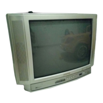
Summary of Contents for Aiwa TV-C2121/KE/KER
- Page 1 KE, KER •...
-
Page 3: Notices Before Repairing
NOTICES BEFORE REPAIRING To make the best use of this equipment, make sure to obey the following items when repairing (or mending). 1. Do not damage or melt the tunicate of the leading Insulation resistance: 7 to 9.5 MΩ (500 V/s) wire on the AC1 side, including the power supply Voltage-withstand: 3 kV for 1 minute cord. - Page 4 Front cabinet Rear cabinet Figure 1-1 Anode cap CRT GND Grip Hook CRT GND Figure 2-1 Anode cap Anode button Hook Figure 2-2...
- Page 5 Anode cap Hook Hook Figure 2-3 Anode cap Anode button Hook Figure 2-4 Anode cap Left Right Figure 3-1 Anode button Installation section Figure 3-2...
- Page 6 (3) Eliminate twisting, etc. of the high-voltage cable and High-voltage cable Anode cap arrange it so that no twisting occurs. (See Figure 3-3) Caution : If the cable is not arranged correctly, the anode cap could turn and cause an installation defect. Figure 3-3 (4) Turn over the rubber cap symmetrically on the left and right.
- Page 7 (6) Apply the hook on one side to the anode button as shown on the figure. (See Figure 3-6) Caution : Check that the hook is held securely. (7) Apply the hook on the other side to the anode button as Hook shown in Figure 3-7.
- Page 8 Front cabinet CN802 (Power cord) CN801 NK C.B CN904 CN903 Figure 4-1 CN401 (Speakers) Figure 5-1 – 8 –...
- Page 11 CHIP RESISTOR PART CODE Chip Resistor Part Coding Figure Resistor Code Value of resistor Chip resistor Dimensions (mm) Symbol Wattage Type Tolerance Resistor Code Form 1/16W 1005 0.35 1/16W 1608 0.45 1/10W 2125 1.25 0.45 1/8W 3216 0.55 E C B B C E E C B G D S...
-
Page 25: Crt Adjustment
CRT ADJUSTMENT SET-UP FOR ADJUSTMENT 1. CRT ADJUSTMENT Because the video signal output from a pattern generator is used as 1-1. Precautions the adjustment signal input during adjustment, the video signal (1) Receive the white raster signal, and then perform aging for at output from the pattern generator must conform with the least 20 minutes. - Page 26 (2) Beam convergence adjustment (4-pole magnet) (3) Beam convergence adjustment (6-pole magnet) With a 4-pole magnet align the G beam with the already aligned Align the R beam with the B beam. The G beam does not R/B beam. move with this adjustment. (magenta) (magenta) (white)
- Page 27 1-3. Beam Landing Adjustment (1) Receive the green raster signal from the pattern generator. As there is occurrence of convergence distortion after (2) Loosen the magnet lock screw, and shift the magnet assembly completing the landing adjustments, be sure to carry out backward (toward the neck).
- Page 28 1-4. Beam Center Convergence Adjustment 1-5. The Surrounding Convergence Adjustment Perform this adjustment after completion of adjustment 1-4. Make adjustments on the convergence with 4-pole and 6-pole magnets. Operate each magnet in relation to the electron beam as (1) Shake the deflecting yoke up, down to the right and left, and shown in Figs.
- Page 31 DN(DOWN) MENU 1/12 1.H POS 50 2.VPOS 50 3.VSIZE 50 4.VLIN EA 50 5.OSDH 50 6.OSDV 50 7.V S-CORR 50 8.H SD SOT 9.VSD SOT 2 : VPOS 50 2 : VPOS 50 2 : VPOS 50 2 : VPOS 50 3 : VSIZE 50 2 : VPOS 50 1 : HPOS 50...
- Page 34 CE NTER...
- Page 41 WIRE ASSY, CRT GND 21U HLDR,LED TV-C2121 KERJ2C,KERJ74M,KEJ2C (FileName:TVC2121.EPS) 13/8/20 BJB-F...


Need help?
Do you have a question about the TV-C2121/KE/KER and is the answer not in the manual?
Questions and answers