Advertisement
POWER
OFF
1
5
10
ELECTRONIC KEYBOARD
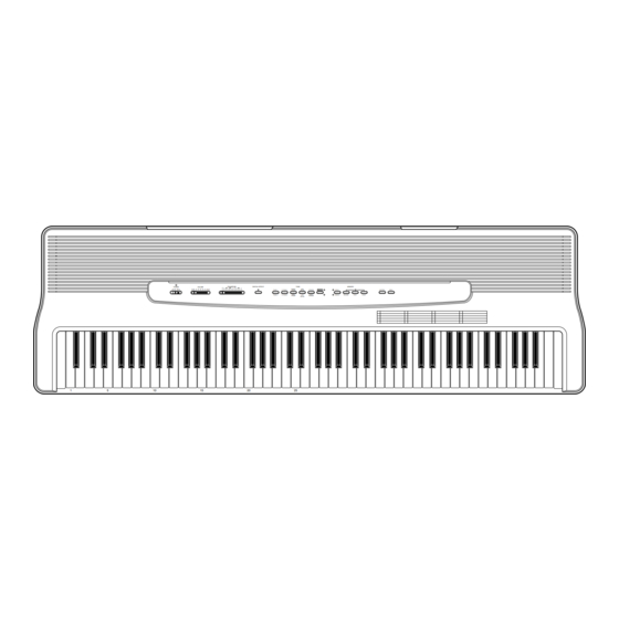
CPS-85
TRANSPOSE
DIGITAL EFFECT
VOLUME
F
#
G A
A B
B C
C
#
D
E
E
F
ON
MIN
MAX
PIANO 1
E. PIANO 1
PIANO 2
E. PIANO 2
15
20
TONE
MEMORY
HARPSI-
PIPE
STRINGS
SELECT
SONG A
CONTROL
DEMO
CHORD
ORGAN
VIBRA-
JAZZ
SYNTH-
SONG B
RECORD
STOP
START
PHONE
STRINGS
ORGAN
25
CPS-85
Advertisement
Table of Contents

Related Manuals for Casio CPS-85


Summary of Contents for Casio CPS-85
- Page 1 CPS-85 TRANSPOSE DIGITAL EFFECT TONE MEMORY POWER VOLUME HARPSI- PIPE PIANO 1 E. PIANO 1 STRINGS SELECT SONG A CONTROL DEMO CHORD ORGAN PIANO 2 E. PIANO 2 VIBRA- JAZZ SYNTH- SONG B RECORD STOP START PHONE STRINGS ORGAN CPS-85...
-
Page 2: Table Of Contents
CONTENTS Page Specifications ............................1 Block Diagram ............................3 Circuit Description ............................. 4 Major Waveforms ............................ 11 Printed Circuit Boards ..........................12 Schematic Diagrams ..........................13 Exploded View ............................19 Parts List ..............................21 SPECIFICATIONS GENERAL Keyboard: 88 full size keys with initial touch response Polyphony: 24 notes maximum Tones:... - Page 3 DAMPER PEDAL (standard mono jack DC 12 V (DC jack Power supply Dual power supply system Batteries: 6 D-size batteries Battery life: Approximately 4 hours on manganese batteries AC adaptor: AD-12 Auto power off: Turns power off approximately 5 minutes after last key operation. Enabled under battery power only, can be disabled manually.
-
Page 4: Block Diagram
BLOCK DIAGRAM Working Storage MIDI RAM (64K-bit) Buttons LSI2 HY6264ALLJ-70 KI0 ~ KI2 FI0 ~ FI10 SI0 ~ SI10 MA12 Keyboard Sound Source ROM MD0 ~ MD15 LSI4 (8M-bit) KC0 ~ KC7 LSI3 GT913F MX23C1610MC-12 MA1 ~ MA19 Reset IC IC 1 RN5VD35AA MA0, MA1... -
Page 5: Circuit Description
CIRCUIT DESCRIPTION KEY MATRIX Note: Each key has two contacts, the first conatct (1) and second contact (2). First contact (1) Second contact (2) — 4 —... -
Page 6: Power Supply Circuit
NOMENCLATURE OF KEYS C#1 D#1 F#1G#1A#1 C#2 D#2 F#2 G#2 A#2 C#3 D#3 F#3 G#3 A#3 C#4 D#4 F#4 G#4 A#4 C#5 D#5 F#5 G#5 A#5 C#6 D#6 F#6 G#6 A#6 C#7 D#7 F#7 G#7 A#7 A0 B0 C1 D1 E1 F1 G1 A1 B1 D2 E2 F2 G2 A2 B2 C3 D3 E3 F3 G3 A3 B3 C4 D4 E4 F4 G4 A4 B4 C5 D5 E5 F5 G5 A5 B5... - Page 7 CPU (LSI4: GT913F) The 16-bit CPU contains a 1k-byte RAM, three 8-bit I/O ports, two timers, a key controller and serial interfaces. The CPU detects key velocity by counting the time between first-key input signal FI and second-key SI from the keyboard.
- Page 8 DIGITAL SIGNAL PROCESSOR (LSI1: HG51B227FB) The DSP receives 16-bit serial sound data from the CPU and adds the selected effect to the sound data using the effect RAM. Then the DSP provides the sound data to the DAC. The DSP also drives LEDs. The following table shows the pin functions of LSI1.
-
Page 9: Filter Block
DAC (IC1: UPD6379GR) The DAC receives 16-bit serial data output from the DSP. The data contains digital sound data of the melody, chord, bass, and percussion for the right and left channels. The DAC converts the data into analog waveforms and output them to each channel separately. Synch signal SCK1 SINC... - Page 10 POWER AMPLIFIER (IC101 : LA4620) The power amplifier is a two-channel amplifier with standby switch. Boot11 IN11+ Input Pre-drive Power OUT11 Amp. Amp. Amp. IN11– – RL Short PoGND1 Protector – IN12– Input Pre-drive Power OUT12 Amp. Amp. Amp. Boot12 Terminal Pop Noise Ripple...
-
Page 11: Major Waveforms
MAJOR WAVEFORMS Power ON 3 KC0 signal 5 CE (MCSBO) signal 1 ADP (POWER) signal JD connector pin 15 LSI3 pin 12 JE connector pin 5 4 KC1 signal 6 OE (MRDB) signal 2 NMI signal JD connector pin 14 LSI3 pin 14 JE connector pin 7 9 Sound signal (L-ch) -
Page 12: Printed Circuit Boards
PRINTED CIRCUIT BOARDS Main PCB JCM423-MA1M Sub PCBs JCM423-MA2M/MA3M/MA4M Top View Top View Bottom View — 12 —... -
Page 13: Schematic Diagrams
SCHEMATIC DIAGRAMS Main PCB JCM423-MA1M — 13 —... - Page 14 Sub PCBs JCM423-MA2M/MA3M/MA4M — 14 —...
- Page 15 Console PCBs JCM423-CN1M/CN2/CN3M — 15 —...
- Page 16 Keyboard PCB JCM886T-KY1M — 16 —...
- Page 17 Keyboard PCB JCM886T-KY2M — 17 —...
- Page 18 Keyboard PCB JCM886T-KY3M — 18 —...
-
Page 19: Exploded View
EXPLODED VIEW — 19 —... - Page 20 SP-2 — 20 —...
-
Page 21: Parts List
PARTS LIST CPS-85 Notes: This parts list does not include the cosmetic parts, which parts are marked with item No. "R-X" in the exploded view. Contact our spare parts department if you need these parts for refurbish. Prices and specifications are subject to change with- out prior notice. - Page 22 Item Code No. Parts Name Specification Main PCB 6925 9150 PCB/ASSY (MA1M) M240661*1 LSI1 2012 4494 LSI,DSP HG51B277FB-1 LSI2 2012 1764 LSI/S-RAM LC3564SM-85-TRM LSI3 2012 5669 LSI/MASK-ROM UPD23C16000WGX-C54 LSI4 2012 5005 LSI,CPU GT913F(T) LSI5 2012 5572 LSI/S-RAM TC55257DFL-70L(EL) LSI6 2105 4746 LSI/D/A CONVERTER UPD6379GR-E1 2105 6340 IC/MOS (RESET IC) RN5VD35AA-TR...
- Page 23 Item Code No. Part Name Specification 6921 6340 KEY/BLACK M311949*1 36 A 6921 4771 SPRING/KEY (W) M411982A-1 52 B 6906 6352 SPRING/KEY (B) M411983B-1 36 B 6915 8551 RUBBER/CONTACT M310664A-1 6915 8541 RUBBER/CONTACT M310663A-1 D701~876 2301 0101 DIODE 1S2473T-77-1 176 B Cases 6919 3281 BUTTON M311398A-1...
- Page 24 8-11-10, Nishi-Shinjuku Shinjuku-ku, Tokyo 160, Japan Telephone: 03-3347-4926 MA0700571A...
Need help?
Do you have a question about the CPS-85 and is the answer not in the manual?
Questions and answers