Casio CTK-2000 Service Manual And Parts List
Hide thumbs
Also See for CTK-2000:
- User manual (46 pages) ,
- Appendix (2 pages) ,
- Implementation manual (22 pages)

Related Manuals for Casio CTK-2000


Summary of Contents for Casio CTK-2000
- Page 1 (without price) CTK-2000 MAY. 2008 CTK-2000 ELECTRONIC KEYBOARD Ver.2 : Nov. 2008 INDEX...
-
Page 2: Table Of Contents
CONTENTS SPECIFICATIONS ------------------------------------------------------------------------------------------ 1 BLOCK AND WIRING DIAGRAM --------------------------------------------------------------------- 2 PCB LAYOUT ----------------------------------------------------------------------------------------------- 3 CIRCUIT DESCRIPTION --------------------------------------------------------------------------------- 4 PRINTED CIRCUIT BOARDS -------------------------------------------------------------------------- 5 DISASSEMBLY --------------------------------------------------------------------------------------------- 8 DIAGNOSTIC PROGRAM ------------------------------------------------------------------------------13 EXPLODED VIEW ----------------------------------------------------------------------------------------16 PARTS LIST ------------------------------------------------------------------------------------------------17 SCHEMATIC DIAGRAMS -------------------------------------------------------------------------------20... -
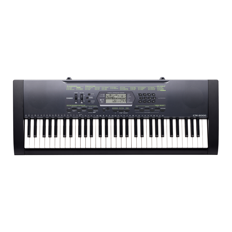
Page 3: Specifications
SPECIFICATIONS Keyboard 61 standard-size keys Maximum Polyphony 48 notes (24 for certain tones) Tones Built-in Tones Sampling Tones Sampling time: 1 second (fixed) Effects: 10 types Reverb 1 to 10, Off Metronome Beats per Measure 0, 2 to 6 Tempo Range 30 to 255 Song Bank Tunes... -
Page 4: Block And Wiring Diagram
BLOCK AND WIRING DIAGRAM M800-KYA2 M800-KYA1 CN801 (13pin) CN802 (13pin) CN803 (16pin) MAIN PCB CN1 (16pin) (M800-MDA1) KC0 ~ KC7,FI0 ~ FI3,SI0 ~ SI3 MD0 ~ MD15 P2ROM KC0 ~ KC7,KI1,KI2,F19,FI10 (Button signal) (16Mbit) MA1 ~ MA21 DB4 ~ DB7,E,R/W,RS (LCD signal) PEDAL LOUT,ROUT Filter IC6... -
Page 5: Pcb Layout
PCB LAYOUT M800-CNB PCB M800-CNA PCB M800-PSA1 PCB M800-MDA1 PCB M800-KYA1 PCB M800-KYA2 PCB Components MAIN PCB M802-MDA1 MPU, ROM(16Mbit), D/D converter, USB terminal SUB PCB M800-PSA1 Power supply circuit, Power amplifer Phones terminal, Pedal terminal, Audio terminal, DC JACK Console PCBs M802-CNA LCD controller, Button... -
Page 6: Circuit Description
CIRCUIT DESCRIPTION KEY MATRIX NOMENCLATURE OF KEYS BUTTON MATRIX TEMPO PLAY/ TONE SONG GAME WAIT METRONOME REPEAT STOP TEMPO START/ RHYTHM TYPE PHRASE FUNCTION DOWN STOP PART KI10 GUIDE PAUSE SAMPLING SELECT – 4 –... -
Page 7: Printed Circuit Boards
PRINTED CIRCUIT BOARDS Main PCB M800-MDA1 Sub PCB M800-PSA1 Top View Top View Bottom View Bottom View – 5 –... - Page 8 Console PCB M800-CNA Console PCB M800-CNB Top View Bottom View – 6 –...
- Page 9 Key PCB M800-KYA1 Key PCB M800-KYA2 – 7 –...
-
Page 10: Disassembly
DISASSEMBLY 1. Remove the battery cover and then battery. 2. Remove 11 screws and then upper case. 3. Remove two lead wires by soldering. 4. Remove cable by soldering. 5. Make the keyboard unit and the main unit apart. Read wire (Red) Cable (CN1) Read wire (Black) –... - Page 11 6. To remove the main PCB (M800-MDA1). 6-1. Remove three screws on the PCB (M800-MDA1). 6-2. Remove three cables by soldering. 6-3. Remove the PCB (M800-MDA1). Cable (CN3) Precaution while assembling the main Connector 3. Number of pins on the PCB and pins on the cable are different.
- Page 12 8. To remove the console PCBs (M800-CNA, M800-CNB). Remove the volume and Power knob. 8-1. 8-2. Remove 29 screws and then the PCBs (M800-CNA and M800-CNB). Caution while assembling: 6 screws fixating the LCD unit must be screwed on in adesignated order.When assembling, be sure to tighten the screws in theorder from 1 - 6 shown in the photo.Failing to do so may cause display malfunctions.
- Page 13 11. To remove the key PCBs (M800-KYA1/KYA2) 11-1. Remove eight screws and then two side cases. 11-2. Remove 21 screws and then the white keys. – 11 –...
- Page 14 11-3. Remove the black keys. 11-4. Remove the hooks and then Key PCB. (M800-KYA1/KYA2) 11-5. Remove the rubber keys. Caution while assembling: There are two types of rubber keys and they are different in length. The longest rubber key ( ) must be installed at the right end.
-
Page 15: Diagnostic Program
DIAGNOSTIC PROGRAM Initial Setting 1. Connect the AC adaptor. 2. "Main" volume: MAX How to start diagnostic program 1. Press and hold the "0", "1" and "2" buttons. TESTMODE 2. Press the "POWER" button. 3. The massage "TESTMODE" is appears on LCD. 4. - Page 16 Message on LCD 2. AC adaptor check Press "3" button. 1:AD1XXX * Make sure that a value "XXX" shown in the illustration is in the range of 000 to 3FF. 000 to 3FF Press "3" button. 1:AD3XXX * Make sure that a value "XXX" shown in the illustration is in the range of 000 to 1FF.
- Page 17 Windows XP Professional (32- bit) *2: Windows Vista (32- bit) Connect CTK-2000 to the computer with a USB cable. Check that the message "USB AUDIO DEVICE" appears in "Device Manager" → "Sound, Video and Game Controller" on the computer monitor.
-
Page 18: Exploded View
EXPLODED VIEW – 16 –... -
Page 19: Parts List
PARTS LIST CTK-2000 Notes: This parts list does not include the cosmetic parts, which parts are marked with item No. “R-X” in the exploded view. Contact our spare parts department if you need these parts for refurbish. 1. Prices and specifications are subject to change without prior notice. - Page 20 1 CTK-2000_DI 2 CTK-2000_CHINA 3 CTK-2000_EU 4 CTK-2000_UK 5 CTK-2000_US Price Item Parts No. Parts Name Specification Remarks Code Main PCB 10304685 PCB ASSY/MDA1 TK-RJM508605*001 10276977 CHIP DIODE L1SS400T1G 79114195 DIODE UDZSTE-175.6B 10211950 I.C NJM2068M-D(TE1) 10269340 IC XC6403FY51PR 10193074 COIL DLW21HN181SQ2L 10238668 CHIP BEAD CORE EBMS160808A102...
- Page 21 1 CTK-2000_DI 2 CTK-2000_CHINA 3 CTK-2000_EU 4 CTK-2000_UK 5 CTK-2000_US Price Item Parts No. Parts Name Specification Remarks Code Accessories 10118186 STAND/MUSIC M311760-001V02 Refurbish 10301447 PANEL RJM508496-001V01 10301445 PANEL/SIDE/L RJM508445-001V01 10301446 PANEL/SIDE/R RJM508446-001V01 10313606 CASE UNIT/MAIN TK-RJM508586*001 10302799 LOWER COVER/A RJM508655-001V01 10302800 LOWER COVER/B RJM508656-001V01...
-
Page 22: Schematic Diagrams
SCHEMATIC DIAGRAMS Main PCB M800-MDA1 Not used: C28,L3 Not used: pin12,pin13 Not used Not used: C170 Not used – 20 –... - Page 23 Sub PCB M800-PSA1 Not used Not used: R153 Not used: FU104 Not used Not used Not used: Not used pin12,pin13 Not used: pin9,pin10 – 21 –...
- Page 24 Console PCB M800-CNA – 22 –...
- Page 25 Console PCB M800-CNB – 23 –...
- Page 26 Keyboard PCBs M800-KYA1/KYA2 – 24 –...
- Page 27 • Addition of The DIAGNOSTIC PROGRAM (P14) Ver.2 : Nov. 2008 • Correction of The BLOCK AND WIRING DIAGRAM (P2) • Correction of The PCB LAYOUT (P3) CASIO COMPUTER CO.,LTD. Overseas Service Division 6-2, Hon-machi 1-Chome Shibuya-ku, Tokyo 151-8543, Japan...
Need help?
Do you have a question about the CTK-2000 and is the answer not in the manual?
Questions and answers