Advertisement
Advertisement
Table of Contents

Subscribe to Our Youtube Channel
Related Manuals for Casio CTK-4200


Summary of Contents for Casio CTK-4200
- Page 1 CTK-4200 JUL. 2011 CTK-4200 ELECTRONIC KEYBOARD INDEX...
-
Page 2: Table Of Contents
CTK-4200 CONTENTS SPECIFICATIONS ................... 1 BLOCK AND WIRING DIAGRAM ..............3 PCB INFORMATION ..................4 CIRCUIT DESCRIPTION ................5 PRINTED CIRCUIT BOARDS ................. 7 DISASSEMBLY ..................... 10 DIAGNOSTIC PROGRAM ................22 EXPLODED VIEW ..................31 PARTS LIST ....................32 SCHEMATIC DIAGRAMS ................35... -
Page 3: Specifications
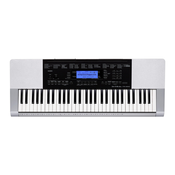
CTK-4200 SPECIFICATIONS Keyboard 61 standard size keys Touch Response 2 types, Off Maximum Polyphony 48 notes (24 for certain tones) Tones Built-in Tones Sampling Tones Up to 8 (Melody Sampling: 5, Drum Sampling: 3)* Up to 10 seconds Functions Layer, Split, Piano/Organ button... - Page 4 CTK-4200 Musical Information Function Tone, Rhythm, Song Bank numbers and names, staff notation, fingering, pedal operation, tempo, measure and beat number, chord name, etc. Inputs/Outputs USB port TYPE B Sustain/Assignable jack Standard jack (sustain, sostenuto, soft, rhythm) Phones/Output jack Stereo standard jack Output Impedance: 140 Ω, Output Voltage: 4.5 V (RMS) MAX...
-
Page 5: Block And Wiring Diagram
CTK-4200 BLOCK AND WIRING DIAGRAM KEYBOARD PCB (M802-KYA1) KEYBOARD PCB (M802-KYA2) CN801 (13 pin) CN802 (10 pin) CN803 (10 pin) CN804 (11 pin) MAIN PCB CN4 (13 pin) CN5 (11 pin) FI0~FI3, FI4~FI7, (M822-MDA1) SI0~SI3, SI4~SI7, KC0~KC4 KC5~KC7 PEDAL (J1) -
Page 6: Pcb Information
CTK-4200 PCB INFORMATION M828-PSA1 M822-MDA1 M802-KYA1 M802-KYA2 Classifi cation Parts Name PCB Name Components MPU, SRAM (4 Mbit), Flash Memory (128 Mbit), Main PCB PCB UNIT/MAIN M822-MDA1 Power Supply Circuit, Filter, SUSTAIN/ASSIGNABLE Jack, USB Port Power Supply Circuit, Power Amplifi er,... -
Page 7: Circuit Description
CTK-4200 CIRCUIT DESCRIPTION „ KEY MATRIX „ Each key has two contacts, the first contact and second contact NOTE: The diagram below illustrates how the contacts work. Second contact First contact „ NOMENCLATURE OF KEYS „ – 5 –... - Page 8 CTK-4200 „ BUTTON MATRIX „ SWO0 SWO1 SWO2 SWO3 SWO4 SWO5 SWO6 RHYTHM, $ ONE BANK, Area1, MUSIC SWI0 LISTEN WATCH TOUCH PRESET PRESET Area2, Area3, SONG SWI1 TONE REMEMBER NEXT BANK STORE, Area4, SWI2 MUSIC AUTO CHALLENGE CHORDS, VAR./...
-
Page 9: Printed Circuit Boards
CTK-4200 PRINTED CIRCUIT BOARDS Main PCB: M822-MDA1 – 7 –... - Page 10 CTK-4200 Sub PCB: M828-PSA1 – 8 –...
- Page 11 CTK-4200 Keyboard PCB: M802-KYA1 Keyboard PCB: M802-KYA2 – 9 –...
-
Page 12: Disassembly
CTK-4200 DISASSEMBLY „ CAUTION „ z The photos show a prototype. The appearance of the instrument, such as color, may „ differ from the actual model. z To avoid damages to the instrument and the floor, lay the instrument on a mattress „... - Page 13 CTK-4200 „ DISASSEMBLY „ A. REMOVE THE PANEL UNITS Left panel unit Main panel unit Right panel unit A-1. Undo 17 or seven screws on the bottom surface of the main unit. NOTE: To remove only the main panel unit, undo seven screws indicated with red circles in the illustration below.
- Page 14 CTK-4200 A-2. Place the main unit with the keys facing up. A-3. Lift the main panel unit and turn it over. NOTE: The main panel unit is connected to the lower case unit with the lead wires and FFCs. Use caution when turn over the main panel unit.
- Page 15 CTK-4200 A-4. Unsolder six lead wires and two FFCs. A-5. Remove the main panel unit. Lead wire (Blue) Lead wire (Brown) FFC (M802-KYA1) FFC (M802-KYA2) Lead wire (White) Lead wire (Green) Lead wire (Black) Lead wire (Red) <Notes On Assembly>...
- Page 16 CTK-4200 • Use wire clips to arrange the two FFCs for the keyboard PCB as shown below. 22 mm Wire clip Cable tie M828-PSA1 PCB Wire clip • Arrange the two FFCs for the keyboard PCB so that they are positioned in the space indicated with a red rectangle in the photo below.
- Page 17 CTK-4200 A-6. Undo one screw and then remove the right panel unit. A-7. Undo one screw and then remove the left panel unit. Left panel unit Right panel unit – 15 –...
- Page 18 CTK-4200 B. REMOVE THE M822-MDA1 PCB (MAIN PCB) B-1. Unsolder three FFCs. B-2. Undo three screws and then remove the M822-MDA1 PCB. FFC (M828-PSA1) M822-MDA1 PCB FFC (M828-PSA1) M822-MDA1 PCB <Notes On Assembly> • The number of pins on the PCB pad differs from that on the cable. Solder in the way that No.1 pin on the cable (orange) is connected to No.1 pad on the PCB.
- Page 19 CTK-4200 C-2. Undo 26 screws and then remove the BACK-LIGHT-UNIT, LCD components and rubber keys. NOTE: There are two types of screws. Be sure to use the correct screw when reassembling. BACK-LIGHT-UNIT BACK-LIGHT-UNIT LCD components – 17 –...
- Page 20 CTK-4200 <Notes On Assembly> • To install the M828-PSA1 PCB of BACK-LIGHT-UNIT, tighten the screws for the LCD part in the order indicated with the numbers below. If not tighten correctly, it may cause the LCD display errors. M828-PSA1 PCB D.
- Page 21 CTK-4200 E. REMOVE THE KEYBOARD E-1. Undo 21 screws and then remove the keys. – 19 –...
- Page 22 CTK-4200 F. REMOVE THE M802-KYA1/KYA2 PCBs (KEYBOARD PCB) M802-KYA1 PCB M802-KYA2 PCB F-1. Disengage the hooks and then remove the M802-KYA1/KYA2 PCBs. – 20 –...
- Page 23 CTK-4200 F-2. Remove five rubber contact strips. NOTE: One rubber contact strip differs in length. This rubber contact strip differs from the others in length. Rubber contact strips <How To Install Rubber Contact Strips> • Lightly insert the tip of a rubber contact strip into the PCB.
-
Page 24: Diagnostic Program
CTK-4200 DIAGNOSTIC PROGRAM „ PREPARATION „ (1) Connect the AC adaptor. NOTE: The AC adaptor (AD-E95100L) for the CTK-4200_DI and CTK-4200_UK is sold separately and does not come with the product. If you do not have the AC adaptor, use six AA-size dry batteries with enough capacity. - Page 25 CTK-4200 „ TEST ITEMS „ Pressing a test button after the diagnostic program was launched or while on the main screen enables the corresponding test item to be tested. Test Items Buttons Note A. BUTTON CHECK B. AC ADAPTOR CHECK AC apaptor C.
- Page 26 CTK-4200 A-2. Press the button in the order indicated in the illustration. NOTE: You cannot cancel this check procedure mid-way. <If the result passes> The confirmation chord sounds and “1:SW00XX” is displayed on the LCD with “XX” indicating the corresponding button number in the illustration.
- Page 27 CTK-4200 A-3. When the “+” button is pressed at the end, a confirmation chord sounds and “1:SW OK!” is displayed on the LCD. A-4. Check to see if the LCD is as shown below. A-5. Press the “0” button to return to the main screen.
- Page 28 CTK-4200 C. ROM CHECK C-1. Press the “5” button to select the “ROM CHECK”. C-2. Press the “1” button to perform the check. C-3. Check to see if the LCD is as shown below. C-4. Press the “0” button to return to the main screen.
- Page 29 CTK-4200 D. RAM CHECK D-1. Press the “6” button to select the “RAM CHECK”. D-2. Press the “1” button to perform the check. D-3. Check to see if the LCD is as shown below. D-4. Press the “0” button to return to the main screen.
- Page 30 CTK-4200 E. ROM VERSION & MODEL CHECK E-1. Press the “9” button to perform the “ROM VERSION CHECK”. The ROM version appears on the LCD. E-2. Check that the ROM version is “19083”. E-3. Press the “9” button to perform the “MODEL CHECK”.
- Page 31 CTK-4200 F. LCD CHECK F-1. Press the “2” button to select the “LCD CHECK”. F-2. Press the “2” button and check to see if all LCDs are lit. F-3. Press the “2” button and check to see if all LCDs are turned off.
- Page 32 CTK-4200 G. PEDAL CHECK G-1. Press the “RHYTHM” button to select the “PEDAL CHECK”. G-2. Press the pedal. G-3. Check to see if the LCD is as shown below. G-4. Press the “0” button to return to the main screen.
-
Page 33: Exploded View
CTK-4200 EXPLODED VIEW For right speaker wires and battery wires – 31 –... -
Page 34: Parts List
1. Prices and specifications are subject to change without prior notice. 2. Refer to the latest “Parts Price Code” at “PARTS FINDER” on the Casio Service WEB site (https://www.servicecasio.com). 3. As for spare parts order and supply, refer to the “GUIDEBOOK for Spare parts Supply”, published separately. - Page 35 CTK-4200 1: CTK-4200_DI 2: CTK-4200_EU 3: CTK-4200_UK 4: CTK-4200_US Q'ty Price Item Code No. Parts Name Specification Remarks Code MAIN PCB 10402681 PCB UNIT/MAIN TK-RJM511401*001 A MDA1 10236624 CONNECTOR/USB UBR24-4K5G00 10206815 JACK/SUSTAIN JY-6314*01-030 10009218 DIODE 1SS400TE61 10211950 IC NJM2068M-D(TE1) 10398240 IC...
- Page 36 CTK-4200 1: CTK-4200_DI 2: CTK-4200_EU 3: CTK-4200_UK 4: CTK-4200_US Q'ty Price Item Code No. Parts Name Specification Remarks Code 10402632 RUBBER BUTTON/A RJM511139-001V01 10402634 RUBBER BUTTON/B RJM511140-001V01 10402636 RUBBER BUTTON/C RJM511141-001V01 10402638 RUBBER BUTTON/D RJM511142-001V01 10402640 RUBBER BUTTON/E RJM511143-001V01 10402642 RUBBER BUTTON/F...
-
Page 37: Schematic Diagrams
CTK-4200 SCHEMATIC DIAGRAMS Main PCB: M822-MDA1 PEDAL (J1) (to PSA1/ CN24) Not used (to PSA1/CN14) (to PSA1/ CN19) (to KYA2/CN804) (to KYA1/CN801) – 35 –... - Page 38 CTK-4200 Sub PCB: M828-PSA1 (1/2) PHONES (J1) DC 9.5 V IN (J2) AUDIO IN (J3) (to BATTERY) (to MDA1/CN1) (to LEFT SPEAKER) Not used LEFT SPEAKER BATTERY RIGHT SPEAKER – 36 –...
- Page 39 CTK-4200 Sub PCB: M828-PSA1 (2/2) (to MDA1/CN2) (to MDA1/CN7) Not used POWER MAIN VOL. SWITCH (VR3) (SW2) (to RIGHT SPEAKER) – 37 –...
- Page 40 CTK-4200 Keyboard PCB: M802-KYA1 (to MDA1/CN4) (to KYA2/CN803) – 38 –...
- Page 41 CTK-4200 Keyboard PCB: M802-KYA2 (to KYA1/CN802) (to MDA1/CN5) – 39 –...
- Page 42 CASIO COMPUTER CO.,LTD. Overseas Service Division 6-2, Hon-machi 1-Chome Shibuya-ku, Tokyo 151-8543, Japan...
Need help?
Do you have a question about the CTK-4200 and is the answer not in the manual?
Questions and answers