Table of Contents
Advertisement
WARNING: IF THE INFORMATION IN THIS MANUAL IS NOT FOLLOWED
EXACTLY, A FIRE MAY RESULT CAUSING PROPERTY DAMAGE, PERSONAL
INJURY OR LOSS OF LIFE.
-- Do not store or use gasoline or other flammable vapors and liquids in vicinity
of this or any other appliance.
WHAT TO DO IF YOU SMELL GAS
l
Do not try to light any appliance.
l
Do not touch any electrical switch; do not use any phone in your building.
l
Immediately call your gas supplier from a neighbor's phone. Follow
the gas supplier's instructions.
l
If you cannot reach your gas supplier, call the fire department.
-- Installation and service must be performed by a qualified installer, service
agency or the gas supplier.
This is an unvented gas-fired heater. It uses air (oxygen) from the room in which it
is installed. Provisions for adequate combustion and ventilation air must be
provided.
Refer to Air For Combustion and Ventilation section on page 6 of this manual.
INSTALLER: DO NOT DISCARD THIS MANUAL – LEAVE WITH HOMEOWNERS FOR
FUTURE REFERENCE
This appliance may be installed in an aftermarket, permanently located,
manufactured (mobile) home, where not prohibited by local codes.
This appliance is only for use with the type of gas indicated on the rating plate.
This appliance is not convertible for use with other gases.
Questions about installation, operation, or troubleshooting? Before returning to your retailer, call our
customer service department toll-free at 1-877-886-5989
CAUTION – FOR YOUR SAFETY
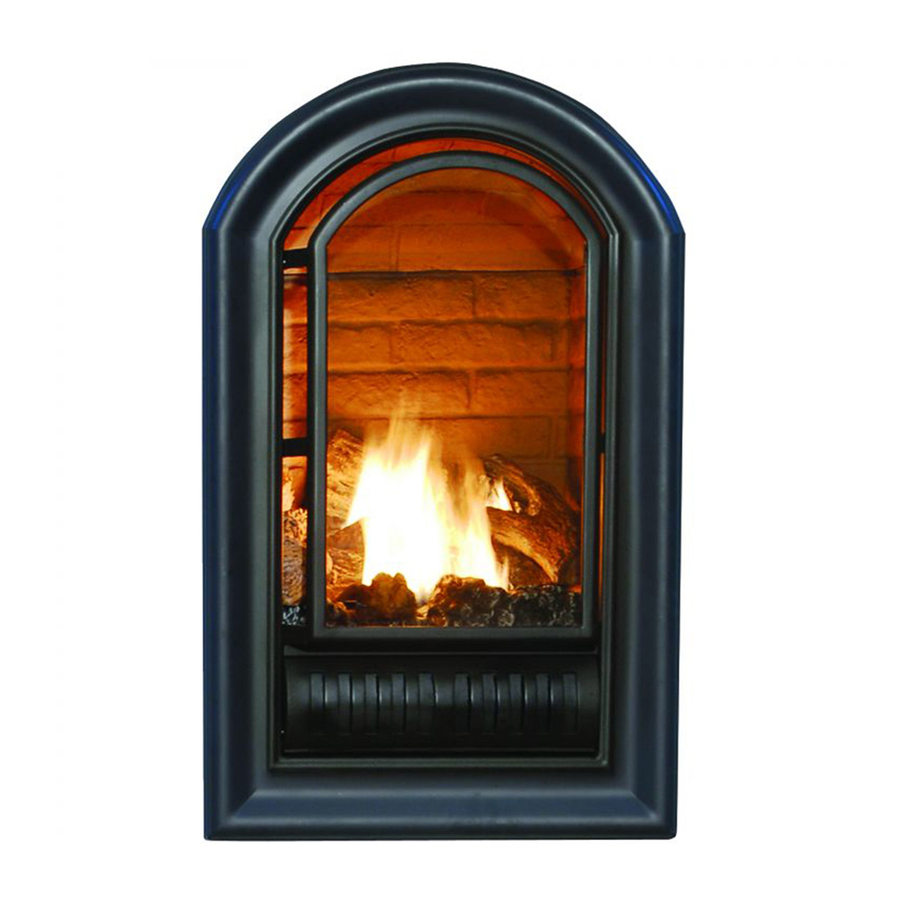
Vent – Free Arched Fireplace
Model: ANI & ALI
HS-AN/LI 200MV–509-0708
Advertisement
Table of Contents

Related Manuals for HearthSense ANI

Summary of Contents for HearthSense ANI
- Page 1 Vent – Free Arched Fireplace Model: ANI & ALI CAUTION – FOR YOUR SAFETY WARNING: IF THE INFORMATION IN THIS MANUAL IS NOT FOLLOWED EXACTLY, A FIRE MAY RESULT CAUSING PROPERTY DAMAGE, PERSONAL INJURY OR LOSS OF LIFE. -- Do not store or use gasoline or other flammable vapors and liquids in vicinity of this or any other appliance.
-
Page 2: Table Of Contents
TABLE OF CONTENTS Important Safety Information.............................3 Air for Combustion and Ventilation..........................6 Installation ...................................8 Operating ....................................17 Cleaning & Maintenance ..............................20 Troubleshooting ................................21 Replacement Parts………………………………………………………………………………………………………………23 WARNING: READ THE INSTALLATION & OPERATION INSTRUCTIONS BEFORE USING THIS APPLIANCE IMPORTANT: Read instructions and warnings carefully before starting installation. Failure to follow these instructions may result in a possible fire hazard and will void the warranty. -
Page 3: Important Safety Information
IMPORTANT SAFETY INFORMATION IMPORTANT: Read this owner’s manual carefully and completely before trying to assemble, operate, or service this heater. Improper use of this heater can cause serious injury or death from burns, fire, explosion, electrical shock, and carbon monoxide poisoning. Installation and service must be performed by a qualified installer, service agency, or local gas supplier. - Page 4 IMPORTANT SAFETY INFORMATION (CONTINUED) This appliance is for use with only the type of gas indicated on the rating plate. This appliance is not convertible for use with other gases. Do not place Propane/LP supply tank(s) inside any structure. Store Propane/LP supply tank(s) outdoors. This heater shall not be installed in a bedroom or bathroom.
-
Page 5: Qualified Installing Agency
QUALIFIED INSTALLING AGENCY Installation and replacement of gas piping, gas utilization equipment or accessories and repair and servicing of equipment should be performed only by a qualified agency. The term “qualified agency” means any individual, firm, corporation, or company that either in person or through a representative is engaged in and is responsible for: a) The installation, testing, or replacements of gas piping or b) The connection, installation, testing, repair, or servicing of equipment;... -
Page 6: Air For Combustion And Ventilation
UNPACKING PRODUCT IDENTIFICATION 1. Remove top inner pack 2. Tilt carton so that fireplace is upright. 3. Remove protective side packaging. 4. Slide fireplace out of carton. 5. Remove protective plastic wrap. 6. Hold the panel lift and pull forward. 7. - Page 7 Unusually tight construction is defined as construction where: a) walls and ceilings exposed to the outside atmosphere have a continuous water vapor retarder with a rating of one perm (6x10-11kg per pa-sec-m2) or less with openings gasketed or sealed and b) weather stripping has been added on windows that can be opened and doors and caulking or sealants are applied to areas such as joints around window and door frames, between sole plates and floors, between wall-ceiling joints, between wall panels, at penetrations for plumbing, electrical, and gas...
-
Page 8: Installation
Ventilation Air From Inside Building This fresh air would come from adjoining unconfined space. When ventilating to an adjoining unconfined space, you must provide two permanent openings: one within 12 inches of the wall connecting the two spaces (see options 1 and 2, Figure 2). - Page 9 See Figure 5 and 11 on page 11. INSTALLATION INTO PRE-FABRICATED MANTELS The fireplace can be positioned into HearthSense cabinet mantels. Figure 5 –Minimum Clearance To Follow the installation instructions for mounting Wall And Ceiling fireplace into mantel.
- Page 10 BUILT-IN FIREPLACE INSTALLATION Built-in installation of this fireplace involves installing fireplace into a framed-in enclosure. This makes the front of the fireplace flush with wall. IMPORTANT: Framing dimensions should allow for wall covering thickness and fireplace facing materials. Adjust rough opening size as necessary to maintain at least the minimum clearance requirements.
- Page 11 Figure10- Face Opening Note: All vertical measurements are from top of fireplace opening to bottom of mantel shelf. All measurements are in inches. Figure 9- Corner Framing Figure11- Mantel Clearances...
-
Page 12: Connecting To Gas Supply
CONNECTING TO GAS SUPPLY WARNING: A qualified technician must connect heater to gas supply. Follow all local codes. CAUTION : Never connect heater directly to the gas supply. This heater requires an external regulator (not supplied). The external regulator between the gas supply and heater must be installed. INSTALLATION ITEMS NEEDED Before installing heater, make sure you have the items listed below: ·... - Page 13 CAUTION: Use new black iron or steel pipe only. Internally tinned copper tubing may be used in certain areas. Check your local codes. Use pipe of 1/2 inch diameter or greater to allow proper volume gas to heater. If pipe is too small, loss of pressure will occur. Installation must include an equipment shutoff valve, union, and plugged 1/8-inch NPT tap.
-
Page 14: Checking Gas Connections
CHECKING GAS CONNECTIONS WARNING : Test all gas piping and connections for leaks after installing or servicing. Correct all leaks immediately. Pressure Testing Gas Supply Piping System Test Pressures In Excess Of 1/2 PSIG(3.5kPa) 1. Disconnect heater with its appliance main gas valve (control valve) and equipment shutoff valve from gas supply piping system. - Page 15 ELECTRICAL WIRING (MILLIVOLT) CAUTION: Label all wires prior to disconnection when servicing controls. Wiring errors can cause Improper and dangerous operation. Verify proper operation after servicing. The millivolt valve is a self-powered combination gas control THAT DOES NOT REQUIRE 110 VAC TO OPERATE.
- Page 16 INSTALLATION Continued WARNING: Failure to position the parts in accordance with these diagrams or failure to use only parts included may result in property damage or personal injury CAUTION: After installation, and periodically thereafter, check to ensure that Figure 17 - Installing Log Set no flame comes in contact with any log.
-
Page 17: Operating
OPERATING INSTRUCTIONS FOR YOUR SAFETY READ BEFORE LIGHTING WARNING: If you do not follow these instructions exactly, a fire or explosion may result causing property damage, personal injury or loss of life. CAUTION: Do not try to adjust heating levels by using the equipment shutoff valve. NOTICE: During initial operation of new heater, logs will give off a paper-burning smell. -
Page 18: Manual Lighting Procedure
OPERATING INSTRUCTIONS 1. STOP! Read “ FOR YOUR SAFETY ” on page 17. 2. Unscrew ignitor cap and install a AAA type battery with the anode (+) pointing out. Replace cap. 3. Make sure manual shutoff valve is fully open. 4. -
Page 19: Inspecting Burners
Figure 27 -Correct Pilot Flame incorrect pilot flame is not touching the thermocouple. This will cause the thermocouple to cool. When the thermocouple cools, Pattern- ANI model the heater will shut down. · If the pilot flame is incorrect, as shown in Figure 28. -
Page 20: Cleaning & Maintenance
CLEANING AND MAINTENANCE WARNING: Failure to keep primary air openings of burners clean may result in sooting and property damage. CAUTION: You must keep control areas, burner, and circulating air passageways of heater clean. Inspect these areas of heater before each use. Have heater inspected yearly by a qualified service person. -
Page 21: Troubleshooting
TROUBLESHOOTING NOTE: Turn the control knob to "off" position first and wait for one minute. Then turn the control knob to on position. Please wait for one minute to allow valve to reset. WARNING: If you smell gas •Shut off gas supply. •Do not try to light any appliance. - Page 22 TROUBLESHOOTING (Continued) OBSERVED PROBLEM POSSIBLE CAUSE REMEDY Burner(s) does not light after 1. Burner orifice is clogged. Burner orifice (see Cleaning ODS/pilot is lit. and maintenance Page 20) or replace burner orifice. 2. Burner orifice diameter is too Replace burner orifice. small.
-
Page 23: Replacement Parts
When ignitor button 1. Ignitor is positioned wrong. 1.Replace ignitor. is pressed in, 2. Ignitor electrode is broken. 2.Replace pilot. 3. Ignitor electrode is not connected to 3.Reconnect ignitor cable. ignitor cable. 4. Ignitor cable is pinched or wet. 4.Free ignitor cable if pinched by any metal or tubing. - Page 24 Replacement Parts on page 23 of this manual. QUANTITY KEY NO PART NUMBER DESCRIPTION AL092-01 Ignitor AN/LI200MV-205 Control Panel MV Valve-ALI MV0.820.636 MV Valve-ANI MV0.820.637 AN/LI200MV-230 Burner Assembly AN/LI200MV-234 Inlet AN/LI200MV-240 Outlet Tube Assembly ODS INTLET TUBE(LP) AN/LI200MV-239 AN/LI200MV-240 ODS INTLET TUBE(NG)
- Page 25 PARTS LIST This list contains replaceable parts used in your heater. When ordering parts, follow the instructions listed under Replacement Parts on page 23 of this manual. KEY NO PART NUMBER DESCRIPTION QUALITY AN/LI200MV-221 Top Reflector AN/LI200MV-101 Top Cover Board AN/LI200MV-104 Back Cover Board AN/LI200MV-110...
Need help?
Do you have a question about the ANI and is the answer not in the manual?
Questions and answers