
Subscribe to Our Youtube Channel
Related Manuals for Dixon ZTR Ram Ultra 61


Summary of Contents for Dixon ZTR Ram Ultra 61
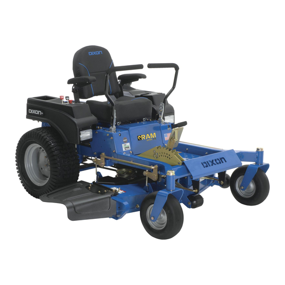
- Page 1 Operator Manual Ram Ultra 61, 25 KOH / 966985401 Ram Ultra 61, 25 KOH BF / 966985402 Please read the operator manual carefully and make sure you understand the instructions before using the machine.
- Page 2 In order to implement improvements, specifications and designs can be altered without prior notification. Note that no legal demands can be placed based on the information contained in these instructions. Use only original parts for repairs. The use of other parts voids the warranty. Do not modify or install non-standard equipment to the unit without consent from the manufacturer.
-
Page 3: Table Of Contents
Contents IntRoDUCtIon..............5 Mowing.tips............... 31 General................ 5 stopping.the.engine..........32 Driving.and.transport.on.Public.Roads....... 5 Manual.transport............33 towing................. 5 Pump.Release.Valves........33 operating..............5 MAIntenAnCe............... 34 Good.service............... 6 Maintenance.schedule..........34 Manufacturing.number........6 Battery............... 36 sYMBoLs.AnD.DeCALs..........7 safety.system............37 sAFetY................ - Page 4 WARNING! Failure to follow cautious operating practices can result in serious injury to the operator or other persons. The owner must understand these instructions, and must allow only trained persons who understand these instructions to operate the mower. Each person operating the mower must be of sound mind and body and must not be under the influence of any mind altering substance.
-
Page 5: Introduction
IntRoDUCtIon Congratulations Towing Thank you for purchasing a Dixon ride-on mower. If machine is equipped with a tow hitch, use extreme This machine is built for superior efficiency to caution when towing. Never allow children or others in rapidly mow primarily large areas. A control panel or on towed equipment. -
Page 6: Good.service
IntRoDUCtIon Good Service retailer. See the certificate in the Service Journal in Dixon’s products are sold only in specialized retail this operator’s manual. stores with complete service. This ensures that you as a customer receive only the best support and service. -
Page 7: Symbols.and.decals
sYMBoLs.AnD.DeCALs These symbols are found on the machine and in the operator’s manual. Study them carefully so that you know what they mean. IMPORTANT INFORMATION WARNING! Xxxx xxxxxx xxxxx xxxx xxxxxxxxx xxxxxx Xxxx xxxxxx xxxxx xxxx xxxxxxxxx xxxxxxxxx. xx xxxxxxxx xxxx xxxxxx. xxxxxx xxxxxxxxx. - Page 8 sYMBoLs.AnD.DeCALs Read Shut off engine and Keep a safe Use on slopes No passengers Operator’s remove key before distance from no greater Manual performing any the machine than 10° maintenance or repair work Whole body Severing of fingers Do not open or Careful backing up, Careful going exposure to...
-
Page 9: Safety
sAFetY Safety Instructions These instructions are for your safety. Read them carefully. WARNING! WARNING! This symbol means that important THIS CUTTING MACHINE IS CAPABLE safety instructions need to be OF AMPUTATING HANDS AND FEET emphasized. It concerns your safety. AND THROWING OBJECTS. FAILURE TO OBSERVE THE FOLLOWING SAFETY INSTRUCTIONS COULD RESULT IN SERIOUS INJURY OR... - Page 10 sAFetY • Operate machine only in daylight or good artificial light. • Do not operate the machine while under the influence of alcohol or drugs. • Watch for traffic when operating near or crossing roadways. • Use extra care when loading or unloading the machine into a trailer or truck.
-
Page 11: Personal.safety.equipment
sAFetY Personal Safety Equipment WARNING! When using the machine, approved personal protective equipment (shown in illustrations) shall be used. Personal protective equipment cannot eliminate the risk of injury but it will reduce the degree of injury if an accident does happen. Ask your retailer for help in choosing the right equipment. - Page 12 sAFetY Children Tragic accidents can occur if the operator is not alert to the presence of children. Children are often attracted to the machine and the mowing activity. Never assume that children will remain out of the path of danger. •...
-
Page 13: Safe.handling.of.gasoline
sAFetY WARNING! The engine must not be started when the driver’s floor plate or any protective plate for the mower deck’s drive belt is removed. Safe Handling of Gasoline To avoid personal injury or property damage, use extreme care in handling gasoline. Gasoline is extremely flammable and the vapors are explosive. -
Page 14: General.maintenance
sAFetY General Maintenance • Never operate machine in a closed area. • Keep all nuts and bolts tight to be sure the equipment is in safe working condition. • Never tamper with safety devices. Check their proper operation regularly. • Keep machine free of grass, leaves, or other debris buildup. - Page 15 sAFetY Sparking can occur when working with the battery and the heavy cables of the starter circuit. This can cause battery explosion, fire or eye injury. Sparking in this circuit can not occur after the chassis cable (normally negative, black) is removed from the battery. •...
-
Page 16: Transport
Do not tow near ditches, system is equipped with a spark arrestor meeting applicable local or canals, and other hazards. state laws (if any). Spark Arrestor A spark arrestor for the muffler is available through your authorized Dixon dealer. -
Page 17: Controls
ContRoLs This operator’s manual describes the Dixon Zero Turn Transmission from the engine is made via belt-driven Rider. The rider is fitted with a Kohler 25 HP* four- hydraulic pumps. Using the left and right steering stroke overhead valve engine. -
Page 18: Steering.control.levers
ContRoLs Steering Control Levers The machine’s speed and direction are continuously variable using the two steering controls. The steering controls can be moved forward or backward about a neutral position. Furthermore, there is a neutral position, which is locked if the steering controls are moved outward. -
Page 19: Parking.brake
ContRoLs Parking Brake The parking brake is found on the right side of the The parking brake is found on the left of the machine. Pull the lever backward to activate the brake and forward to release it. IMPORTANT INFORMATION The machine must stand absolutely still when applying the parking brake. -
Page 20: Choke.control
ContRoLs Choke Control The choke control is used for cold starts in order to provide the engine with a richer fuel mixture. For cold starts the control should be pushed to the ON position. WARNING! Gasoline is highly flammable. Observe caution and fill the tank outdoors (see the safety instruction). -
Page 21: Hour.meter
ContRoLs Seat Adjustment Lever The seat can be adjusted lengthways. When making adjustments, the lever under the front edge of the seat is moved to the left (as seen by the driver in the seat), after which the seat can be moved backward or forward. -
Page 22: Fuel.shut.off.valve
Recommended air pressure is 15 psi. (1 bar) Tracking must be checked on a flat and level concrete or blacktop surface. If the unit still does not track straight contact your Dixon workshop for adjustments. WARNING! -
Page 23: Fuel.tank
ContRoLs Fuel Tank Read the safety instructions before refueling. The machine has one fuel tank, just behind the seat. The tank capacity is 5.7 gallons (22 liters). Make sure the fuel cap is properly tightened and the cap gasket is not damaged. The engine will run on a minimum of 85-octane unleaded gasoline (no oil mix). -
Page 24: Operation
oPeRAtIon Steering Read the Safety section and following pages, if you are unfamiliar with the machine. To move forward and backward Training The direction and speed of the mower’s movements is effected by the movement of the control lever(s) Zero turn mowers are far more maneuverable than on each side of mower. -
Page 25: Before.starting
oPeRAtIon Before Starting • Read the sections Safety Instructions and Controls before starting the machine. • Perform the daily maintenance before starting (see Maintenance Schedule in the Maintenance section). • Check that there is sufficient fuel in the fuel tank. •... - Page 26 oPeRAtIon Move the steering controls outward to the locked (outer) neutral position. 8061-021 Place controls in neutral position Move the throttle to the middle position. WARNING! Engine exhaust and certain vehicle components contain or emit chemicals considered to cause cancer, birth defects or other reproductive system damage.
- Page 27 oPeRAtIon Open the fuel valve. 8050-010 Open the fuel valve Press in and turn the ignition key to the start position 8050-135 Turn to START position When the engine starts, immediately release the ignition key back to the run position. IMPORTANT INFORMATION Do not run the starter for more than 5 seconds each time.
-
Page 28: Weak.battery
oPeRAtIon Weak Battery WARNING! Lead-acid batteries generate explosive gases. Keep sparks, flame and smoking materials away from batteries. Always wear eye protection when around batteries. IMPORTANT INFORMATION Your mower is equipped with a 12-volt negative grounded system. The other vehicle must also be a 12-volt negative grounded system. -
Page 29: Running
oPeRAtIon Running Release the parking brake by moving the lever downward. NOTE: The mower is equipped with an operator presence system. When the engine is running, any attempt by the operator to leave the seat without first setting the parking brake will shut off the engine. -
Page 30: Operating.on.hills
oPeRAtIon Operating On Hills Read the Safety Instructions “Driving on Slopes” in the “Safety Instructions”. WARNING! Do not drive up or down hills with slopes greater than 10 degrees. Do not drive across slopes. • The slowest speed possible should be used before starting up or down hills. -
Page 31: Mowing.tips
oPeRAtIon Mowing Tips WARNING! • Observe and flag rocks and other fixed objects to avoid collisions. Clear the lawn of stones and other objects that can be thrown out by the • Begin with a high cutting height and reduce it until blades. -
Page 32: Stopping.the.engine
oPeRAtIon Stopping the Engine Allow the engine to idle a minute in order to attain normal operating temperature before stopping it, if it has been worked hard. Avoid idling the engine for longer periods, as there is a risk of the spark plugs fouling. -
Page 33: Manual.transport
oPeRAtIon Manual Transport IMPORTANT INFORMATION Tighten the valve moderately. Do not overtighten the valve when closing. That can damage the valve seat. Pump Release Valves Pump release valves are located at the front and rear of the pump. They are used to release the system so the machine may be moved by hand when not running. -
Page 34: Maintenance
MAIntenAnCe Maintenance Schedule The following is a list of maintenance procedures that an authorized service workshop is recommended to must be performed on the machine. For those points maintain your machine in the best possible condition not described in this manual, visit an authorized and to ensure safe operation. - Page 35 MAIntenAnCe Daily Weekly Maintenance interval in least hours once each Maintenance Before After year ● Check/adjust throttle cable ● ● Check the condition of belts, belt pulleys ■ ■ Change the engine oil ■ ■ Replace the engine oil filter ■...
-
Page 36: Battery
MAIntenAnCe Battery Your mower is equipped with a maintenance free Always use protective glasses when battery that does not need servicing. However, handling the battery. periodic charging of the battery with an automotive type battery charger will extend its life. •... -
Page 37: Safety.system
Visually check that no damage is found on the lever, links, or switch belonging to the parking brake. Perform a standstill test and check that there is sufficient braking action. To adjust the parking brake, contact the Dixon service workshop. WARNING! Faulty adjustment can result in reduced braking ability and can cause an accident. -
Page 38: V-Belts
MAIntenAnCe V-belts Check every 100 hours of operation. Check for severe cracking and large nicks. NOTE: The belt will show some small cracks in normal operation. The belts are not adjustable. Replace belts if they begin to slip from wear. Deck Belt Park on a level surface. -
Page 39: Pump.belt
MAIntenAnCe Pump Belt Replacing Pump Belt Park the mower on a level surface. Engage the parking brake. Belt removal Remove the deck belt (see Deck Belt Removal in this section of the manual). Remove clutch stop to access the belt. Disconnect clutch wire. -
Page 40: Blade.replacement
(down) or “THIS SIDE UP” facing deck and cutter housing. nstall and tighten blade bolt securely. Torque blade bolt to 45-55 ft/lbs (60-75 Nm). IMPORTANT INFORMATION Special blade bolt is heat treated. Replace with a Dixon bolt if required. Do not use lower grade hardware than specified. -
Page 41: Adjusting.the.mower.deck
MAIntenAnCe Adjusting the Mower Deck WARNING! Before performing any service or adjustment checklist: 1. Engage the parking brake. 2. Place the Blade switch in the disengaged position. 3. Turn ignition switch to “OFF” position and remove the key. 4. Make sure the blades and all moving parts have completely stopped. 5. -
Page 42: Anti-Scalp.rollers
MAIntenAnCe Anti-Scalp Rollers Anti-scalp rollers are properly adjusted when they are just slightly off of the ground when the deck is at the desired cutting height in the operating position. Anti-scalp rollers then keep the deck in the proper position to help prevent scalping in most terrain conditions. -
Page 43: Caster.wheels
MAIntenAnCe Caster Wheels Check every 200 hours. Check that wheels rotate freely. If wheels do not rotate freely take the unit to your dealer for service. Foam filled tires or solid tires will void the warranty. Removal and installation of caster wheel Remove nut (1) and caster bolt (2). -
Page 44: Lubrication
LUBRICAtIon 8011-672-6 12/12.every.year Lubricate.with.grease.gun Lubricate.with.oil.can 1/52.every.Week oil.change Level.check 1/365.every.day Filter.change *Change transaxles (transmission) filters. General Remove the ignition key to prevent unintentional Wipe away excess grease after lubrication. movements during lubrication. It is important to avoid getting lubricant on the belts When lubricating with an oil can, it must be filled with or the drive surfaces on the belt pulleys. -
Page 45: Front.wheel.mount
LUBRICAtIon Front Wheel Mount Lubricate with a grease gun, one zerk for each wheel mount, until the grease is forced out. Use only good quality bearing grease. Grease from well-known brand names (petrochemical companies, etc.) usually maintains a good quality. Front Wheel Bearings Lubricate with a grease gun, one zerk for each set of wheel bearings, until the grease is forced out. -
Page 46: Hydraulic.pump
LUBRICAtIon Hydraulic Pump Fluid Change This transaxle is designed with an external filter for ease of maintenance. To ensure constant fluid quality levels and longer life an oil filter change interval of every 200 hours is recommended. The following procedure can be performed with the pump installed in the vehicle, and the vehicle on level ground. -
Page 47: Troubleshooting
tRoUBLesHootInG Problem Cause The engine will not start. • Blade lever is engaged. • Steering controls are not locked in neutral position. • Driver is not sitting in driver’s seat. • Parking brake is not activated. • Battery is dead. •... - Page 48 tRoUBLesHootInG Problem Cause The engine seems weak. • Clogged air filter. • Fouled spark plugs. • Carburetor incorrectly adjusted. The engine overheats. • Clogged air intake or cooling fins. • Engine overloaded. • Poor ventilation around engine. • Defective engine speed regulator. •...
-
Page 49: Winter.storage
Drain the fuel into purchase year, model, type, and serial number. an approved container outdoors and Always use genuine Dixon spare parts. far away from open flame. Never use An annual checkup at an authorized service workshop gasoline for cleaning. Use a degreaser is a good way to ensure that the machine performs its and warm water instead. -
Page 50: Schematics
sCHeMAtIC 8053-002... -
Page 51: Technical.data
teCHnICAL.DAtA Torque Specifications Engine crankshaft bolt 50 ft/lb (67 Nm) Standard " fasteners 18 ft/lb (25 Nm) Deck pulley bolts 150 ft/lb (203 Nm) Standard " fasteners 33 ft/lb (44 Nm) Lug nuts 75 ft/lb (100 Nm) Standard " fasteners 52 ft/lb (70 Nm) Blade bolt 90 ft/lb (122 Nm) - Page 52 teCHnICAL.DAtA 966985401, 966985402 Engine Manufacturer Kohler Type Courage Power 25 hp* Lubrication Pressure with oil filter Oil capacity excluding filter 1.6 qts/ 1.5 liters Oil capacity including filter 1.7 qts / 1.6 liters Engine oil SAE 10W30, 10W40, 5W20, 5W30, API SF-SJ Fuel Min 87 octane unleaded (Max ethanol 10%, Max MTBE 15%) Fuel tank capacity...
- Page 53 teCHnICAL.DAtA 966985401, 966985402 Equipment Cutting width 61" / 155cm Cutting height 1½ - 4½" / 3.8 - 11.4 cm Number of blades Blade length 21" / 43 cm Nose Rollers Sprung seat Standard Hinged armrests Hour Meter Standard Blade engagement Electromagnetic clutch Deck construction 11 gauge fabricated...
-
Page 54: Conformity.certificates
ConFoRMItY.CeRtIFICAtes USA requirements CE requirements Labels are placed on the engine and/or in the engine If required, vibration data corresponding to Directive compartment stating that the machine will fulfill the 2002/44/EC is given in the Technical Data Section. requirements. This is also applicable to special The Declaration of Conformity is included in the requirements for any of the states, (California emission literature packet. -
Page 55: Warranty
Two years - 100% parts and labor subject to the conditions and limitations described herein for a period of two years from date of purchase by the original owner. Third year - limited to 100% parts cost as shown in the current Dixon Parts Price List and subject to the conditions and limitations as described herein. -
Page 56: Service.journal
seRVICe.JoURnAL Action Date, mtr reading, stamp, sign Delivery Service 1. Charge battery. 2. Adjust tire pressure of all wheels according to Technical Data. 3. Mount the steering controls in the normal position. 4. Connect the contact box to the cable for the seat’s safety switch. 5. - Page 57 seRVICe.JoURnAL Action Date, mtr reading, stamp, sign After the First 10 Hours 1. Change engine oil. 25-Hour Service 1. Check the fuel pump’s air filter. 2. Check the hydraulic system’s oil level. 3. Check the tire pressures. 4. Lubricate the belt adjuster, mower deck. 5.
- Page 58 seRVICe.JoURnAL Action Date, mtr reading, stamp, sign 50-Hour Service 1. Perform the 25-hour service. 2. Clean/replace the air cleaner’s filter cartridge (paper filter) (shorter intervals for dusty operating conditions). 3. Change engine oil. 4. Lubricate according to lubrication chart. 5. Check/adjust the parking brake. 100-Hour Service 1.
- Page 59 seRVICe.JoURnAL Action Date, mtr reading, stamp, sign 300-Hour Service 1. Perform the 25-hour service. 2. Perform the 50-hour service. 3. Perform the 100-hour service. 4. Check/adjust the mower deck. 5. Clean the combustion chamber and grind the valve seats. 6. Check the engine valve clearance. 7.
- Page 60 seRVICe.JoURnAL Action Date, mtr reading, stamp, sign...
- Page 61 seRVICe.JoURnAL Action Date, mtr reading, stamp, sign...
- Page 62 seRVICe.JoURnAL Action Date, mtr reading, stamp, sign...
- Page 64 P/N 115 354727R1 01/06/10...
Need help?
Do you have a question about the ZTR Ram Ultra 61 and is the answer not in the manual?
Questions and answers