Table of Contents
Advertisement
Advertisement
Table of Contents

Related Manuals for Dixon ZTR RAM 44


Summary of Contents for Dixon ZTR RAM 44
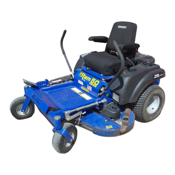
- Page 1 Operator's manual RAM 44 / 968999551, RAM 50 / 968999552 RAM MAG 44 / 968999559, RAM MAG 50 / 968999561 RAM MAG 50 / 968999562, RAM MAG 44 / 968999650 RAM MAG 50 / 968999651 Please read the operator’s manual carefully and make sure you understand the instructions before using the machine.
-
Page 3: Table Of Contents
OPERATOR’S MANUAL Contents Contents...1 Introduction ...3 Congratulations...3 General ...3 Driving and Transport on Public Roads ...3 Towing ...3 Operating ...3 Good Service ...4 Manufacturing Number ...4 Symbols and Decals ...5 Safety Instructions...7 General Operation ...7 Personal Safety Equipment ...9 Slope Operation ...9 Children...10 Maintenance ...11 Transport...14... - Page 4 WARNING! Failure to follow cautious operating practices can result in serious injury to the operator or other persons. The owner must understand these instructions, and must allow only trained persons who understand these instructions to operate the mower. Each person operating the mower must be of sound mind and body and must not be under the influence of any mind altering substance.
-
Page 5: Introduction
INTRODUCTION Introduction Congratulations Thank you for purchasing a Dixon ride-on mower. This machine is built for the greatest efficiency and rapid mowing primarily of large areas. Controls in one place and a hydrostatic transmission regulated by steering controls also contribute to the machine’s performance. This manual is a valuable document. -
Page 6: Good Service
Good Service Dixon’s products are sold all over the world and only in specialized retail stores with complete service. This ensures that you as a customer receive only the best support and service. Before the product is delivered, the machine has, for example, been inspected and adjusted by your retailer, see the certificate in the Service Journal in this operator’s manual. -
Page 7: Symbols And Decals
SYMBOLS AND DECALS Symbols and Decals These symbols are found on the machine and in the operator’s manual. Study them carefully so that you know what they mean. WARNING! Xxxxxxx xxxx xxxxxxxx xxx x Xxxxx xxxxxx xx. xx xxxxxxxx xxxxx xxx xx. Used in this publication to notify the reader of a risk of personal injury or death, particularly if the reader does not follow instructions given in the manual. - Page 8 SYMBOLS AND DECALS Shut off engine Read & remove key Operator´s before Manual. performing any maintenance or repair work. Whole Severing body of fingers exposure & toes. to thrown objects. Moving sharp blades under cover English- Keep a safe Use on distance from slopes no the machine.
-
Page 9: Safety Instructions
SAFETY INSTRUCTIONS Safety Instructions These instructions are for your safety. Read them carefully. WARNING! This symbol means that important safety instructions need to be emphasized. It concerns your safety. IMPORTANT: THIS CUTTING MACHINE IS CAPABLE OF AMPUTATING HANDS AND FEET AND THROWING OBJECTS. - Page 10 SAFETY INSTRUCTIONS • Disengage blades when not mowing. Shut off engine and wait for all parts to come to a complete stop before cleaning the machine, removing the grass catcher, or unclogging the discharge guard. • Operate machine only in daylight or good artificial light.
-
Page 11: Personal Safety Equipment
SAFETY INSTRUCTIONS Personal Safety Equipment WARNING! When using the machine, approved personal protective equipment (shown in illustrations) shall be used. Personal protective equipment cannot eliminate the risk of injury but it will reduce the degree of injury if an accident does happen. -
Page 12: Children
SAFETY INSTRUCTIONS • Use extra care while operating machine with grass catchers or other attachments; they can affect the stability of the machine. Do not use on steep slopes. • Do not try to stabilize the machine by putting your foot on the ground. •... -
Page 13: Maintenance
SAFETY INSTRUCTIONS Maintenance WARNING! The engine must not be started when the driver’s floor plate or any protective plate for the mower deck’s drive belt is removed. Safe Handling of Gasoline To avoid personal injury or property damage, use extreme care in handling gasoline. Gasoline is extremely flammable and the vapors are explosive. - Page 14 SAFETY INSTRUCTIONS the sun may otherwise cause the fuel to expand and overflow. General Maintenance • Never operate machine in a closed area. • Keep all nuts and bolts tight to be sure the equipment is in safe working condition. •...
- Page 15 SAFETY INSTRUCTIONS • Acid in the eyes can cause blindness, contact a doctor immediately. • Be careful when servicing the battery. Explosive gases form in the battery. Never perform maintenance on the battery when smoking or near open flames or sparks. The battery can explode and cause serious injury/damage.
-
Page 16: Transport
SAFETY INSTRUCTIONS recommended by the manufacturer. Only use approved repair parts for the machine. • The blades are sharp and can cause cuts and gashes. Wrap the blades or use protective gloves when handling them. • Check the parking brake’s functionality regularly. -
Page 17: Customer Responsibilities
SAFETY INSTRUCTIONS Customer responsibilities • Read and observe the safety rules. • Follow a regular schedule in maintaining, caring for and using your mower. • Follow the instructions under "Maintenance” and "Storage” sections of this owner’s manual. • This machine has no brain. Use yours! WARNING! This mower is equipped with an internal combustion engine and should not be used on or near any unimproved forest-covered, bush-covered or grass-covered... -
Page 18: Controls
Controls This operator’s manual describes the Dixon Zero Turn Rider. The rider is fitted with a Briggs & Stratton, Kohler, Honda or Kawasaki four stroke V-twin engine developing 20 - 26 horse power. Transmission from the engine is made via two belt-driven hydraulic transaxles, one for each drive wheel. -
Page 19: Parking Brake
1. Parking Brake IMPORTANT INFORMATION The machine must be absolutely standing still when applying the parking brake. The parking brake is found on the left of the machine. Pull the lever backward to activate the brake and forward to release it. 2. -
Page 20: Fuel Shut Off Valve
positions when standing still or do not fit in the slots for moving the controls outward, they can be adjusted. Tracking If the mower is not tracking straight, check the air pressure in both rear tires. Recommended air pressure is 15 psi. (1 bar) Tracking must be checked on a flat and level concrete or blacktop surface. -
Page 21: Refueling
5. Refueling Read the safety instructions before refueling. The machine has one fuel tank, just behind the seat. The tank volume is 5.4 gallons (20.4 liters). Make sure the fuel cap is properly tightened and the cap gasket is not damaged. The engine will run on a minimum of 85- octane unleaded gasoline (no oil mix). -
Page 22: By Pass Linkage
6. By pass linkage When pushing or pulling the mower, be sure to engage the IZT (Integrated Zeroturn Transaxle) bypass linkages. The IZT bypass linkages are located on the rear of the frame, below the rear engine guard. • Raise the deck into the highest cutting position. -
Page 23: Hour Meter
8. Hour Meter The hour meter displays the total operating time. It will flash CHG OIL (Change Oil) at 50 hour intervals. The flash duration is one hour before and one hour after the interval. The CHG OIL icon will come on and shut off automatically. -
Page 24: Throttle Control
IMPORTANT INFORMATION Do not run the starter for more than five seconds each time. If the engine does not start, wait about 10 seconds before re- trying. 11. Throttle Control The throttle control regulates the engine speed and thereby the rate of rotation of the blades, assuming the blade switch is pulled out, see Engaging the Mower Deck. -
Page 25: Cutting Height Pedal
13. Cutting height pedal The cutting deck height is obtained by pressing the foot pedal lift arm forward and releasing the transport latch. Then lower the deck to the preset height. To raise the deck push forward on the foot pedal lift arm until the transport latch locks. -
Page 26: Operation
Operation Read "Safety Instructions", the "Controls" section and following pages, if you are unfamiliar with the machine. Conduct all daily maintenance on the machine before starting. Training Zero turn mowers are far more manueverable than typical riding mowers due to their unique steering capabilities. -
Page 27: Before Starting
Before Starting • Read the sections Safety Instructions and Controls before starting the machine. • Perform the daily maintenance before starting (see Maintenance Schedule in the Maintenance section). • Check that there is sufficient fuel in the fuel tank. • Make sure all guards are in place and in good condition. - Page 28 Disengage the mower blades by depressing the blade switch. Move the steering controls outward to the locked (outer) neutral position. Move the throttle to the middle position. English- OPERATION Depress the control for disengaging the mower deck Steering controls in the outward, locked neutral position Set the throttle 8011-668 8011-724...
- Page 29 If the engine is cold, the choke control should be pulled out to its extents. Open the fuel shut off valve. Press in and turn the ignition key to the start position. OPERATION Set the choke control Open the fuel shut off valve Turn to the start position 8050-148 CZ15...
- Page 30 10. When the engine starts, immediately release the ignition key back to the run position. IMPORTANT INFORMATION Do not run the starter for more than 10 seconds each time. If the engine does not start, wait about 60 seconds before re- trying.
-
Page 31: To Start An Engine With A Weak Battery
To start an engine with a weak battery WARNING! Lead-acid batteries generate explosive gases. Keep sparks, flame and smoking materials away from batteries. Always wear eye protection when around batteries. If your battery is too weak to start the engine, it should be recharged. -
Page 32: Running
Running Release the parking brake by moving the lever forward. Your mower is equipped with an operator presence system. When the engine is running, any attempt by the operator to leave the seat without first setting the parking brake will shut off the engine. Move the steering controls to the neutral position (N). -
Page 33: Operating On Hills
or backward respectively. In order, for example, to turn right while moving forward, move the right control towards the neutral position. The rotation of the right wheel is reduced and the machine turns to the right. Turning on the spot can be achieved by moving one control backward (behind the neutral position) and carefully moving the other steering control forward from its... -
Page 34: Mowing Tips
Mowing Tips • Observe and flag rocks and other fixed objects to avoid collisions. • Begin with a high cutting height and reduce it until the desired mowing result is attained. The average lawn should be cut to 2 1/2" (64 mm) during the cool season and over 3"... -
Page 35: Stopping The Engine
Stopping the Engine Allow the engine to idle a minute in order to attain normal operating temperature before stopping it, if it has been worked hard. Avoid idling the engine for longer periods, as there is a risk of the spark plugs fouling. Disengage the mower deck by depressing the blade switch. -
Page 36: Moving By Hand
Moving by Hand WARNING! No adjustments or maintance to be carried out unless: - the engine stopped, - the ignition key has been removed, - the parking brake is on. When pushing or pulling the mower, be sure to engage the IZT (Integraded Zeroturn Transaxle) bypass linkages. -
Page 37: Maintenance
Maintenance Maintenance Schedule The following is a list of maintenance procedures that must be performed on the machine. For those points not described in this manual, visit an authorized service workshop. An annual service carried out by an authorized service workshop is recommended to maintain your machine in the best possible condition and to ensure safe operation. - Page 38 Maintenance Check/adjust throttle and choke cables Check the condition of belts, belt pulleys, etc. Change the engine oil Replace the engine oil filter Clean/replace the spark plugs Replace the fuel filter Replace the air filter (paper filter) Check the caster wheels (every 200 hours) Clean the cooling fins Replace the air cleaner’s pre-filter Check/adjust the mower deck...
-
Page 39: Battery
Battery Your mower is equipped with a maintenance free battery and does not need servicing. However, periodic charging of the battery with an automotive type battery charger will extend its life. • Keep battery and terminals clean. • Keep battery bolts tight. •... -
Page 40: Ignition System
Connect BLACK grounding cable to negative (-) battery terminal with remaining hex bolt and hex nut. 10. Tighten securely. 11. Close terminal access doors. 12. Lower seat. Ignition System The engine is equipped with an electronic ignition system. Only the spark plugs require maintenance. -
Page 41: Checking The Safety System
Checking the Safety System The machine is equipped with a safety system that prevents starting or driving under the following conditions. The engine can only be started when: The mower deck is disengaged. The steering controls are in the outer, locked neutral position. -
Page 42: Checking The Engine's Cooling Air Intake
Checking the Engine's Cooling Air Intake Check that the engine’s cooling air intake is free from leaves, grass, and dirt. If the cooling air intake is clogged, engine cooling deteriorates, which can lead to engine damage. The cooling air intakes rotates when the engine is running. -
Page 43: Replacing The Air Filter
Replacing the Air Filter - Briggs & Stratton Engine Standard air filter If the engine seems weak or runs unevenly, the air filter may be clogged. If run with a dirty air filter, the spark plugs can become fouled disrupting operation. For this reason, it is important to replace the air filter regularly (see the heading Maintenance Schedule for the proper service interval). - Page 44 Replacing Heavy Duty Air Filter (Kohler) If the engine seems weak or runs unevenly and the dust load indicator has turned red the air filter may be clogged. If run with a clogged air filter, disruption of operation can occur. Cleaning/replacing the air filter is carried out as follows: Only do so when the dust indicator is red.
- Page 45 Replacing the Air Filter (Honda) Standard air filter If the engine seems weak or runs unevenly, the air filter may be clogged. If run with a dirty air filter, the spark plugs can become fouled, disrupting operation. It is important to replace the air filter regularly (see the heading Maintenance Schedule for the proper service interval).
-
Page 46: Replacing The Fuel Filter
Replacing the Fuel Filter Replace the line-mounted fuel filter every 100 hours (once per season) or more regularly if it is clogged. Replace the filter as follows: Move the hose clamps away from the filter. Use flat-nosed pliers. Pull the filter loose from the hose ends. Push the new filter into the hose ends. -
Page 47: Checking The Parking Brake
Checking the Parking Brake Visually check that no damage is found on the lever, links, or switch belonging to the parking brake. Perform a stand-still test and check that there is sufficent braking action. To adjust the parking brake, contact the Husqvarna service workshop. -
Page 48: Izt Belt
Deck belt installation NOTE: For ease in installing the deck belt, refer to the routing decal on the front edge of the deck. • Wrap the deck belt around the electric clutch that is located on the engine shaft. • Push the rest of the belt through the IZT(Integraded Zeroturn Transaxle) support and up onto the deck. - Page 49 IZT belt To replace IZT (Integraded Zeroturn Transaxle) belt Park the mower on a level surface. Engage the park brake. IZT belt removal NOTE: Be careful not to damage the fan blades on the IZT as this can affect cooling or damage the IZT •...
-
Page 50: Checking The Blades
Checking the Blades In order to attain the best mowing effect, it is important that the blades are well sharpened and not damaged. WARNING! Blades are sharp. Protect your hands with gloves and/or wrap blades with a heavy cloth when handling. - Page 51 Blade replacement: WARNING! Blades are sharp. Protect your hands with gloves and/or wrap blades with a heavy cloth when handling. • Remove blade bolt by turning counterclockwise. IMPORTANT INFORMATION To ensure proper assembly, center hole in blade must align with star on cutter housing.
-
Page 52: Adjusting The Mower Deck
Adjusting the Mower Deck WARNING! Before performing any service or adjustment checklist: 1. Engage the parking brake. 2. Place the Blade switch in the disengaged position. 3. Turn ignition switch to “OFF” position and remove the key. 4. Make sure the blades and all moving parts have completely stopped. 5. - Page 53 To adjust anti-scalp rollers Anti-scalp rollers are properly adjusted when they are just slightly off of the ground when the deck is at the desired cutting height in the operating position. Anti-scalp rollers then keep the deck in the proper position to help prevent scalping in most terrain conditions.
-
Page 54: Cleaning And Washing
Cleaning and Washing Regular cleaning and washing, especially under the mower deck, will increase the machine’s lifespan. Make it a habit to clean the machine directly after use (after it is cooled), before the dirt sticks. Do not spray water on the top of the mower deck. -
Page 55: Parking Brake
Parking brake To adjust parking brake Jack up unit and support properly with jack stands. Allow clearance to work at rear transaxles. Before making any adjustments: Set park brake. Measure the distance between the rod swivel pin and the brake arm washer. With the brake engaged, there should be a gap of 1/8”... -
Page 56: Lubrication
Lubrication Lubrication Schedule 12/12 Every year Lubricate with grease gun 1/52 Every Week 1/365 Every day Change transaxles (transmission) filters. General Remove the ignition key to prevent unintentional movements during lubrication. When lubricating with an oil can, it must be filled with engine oil. When lubricating with grease, unless otherwise stated, use a high grade molybdenum disulfide grease. -
Page 57: Lubricating The Cables
Lubricating the Cables If possible, grease both ends of the cables and move the controls to end stop positions when lubricating. Refit the rubber covers on the cables after lubrication. Cables with sheaths will bind if they are not lubricated regularly. If a cable binds, it can disrupt operation. If a cable binds, remove the cable and hang it vertically. - Page 58 4. Deck outer spindle Lubricate using a grease gun, one zerk, each side 2-3 strokes. Use only good quality bearing grease. 5. Engine Oil Changing the Engine Oil The engine oil should be changed for the first time after 5-8 hours of operation. Thereafter, it should be changed every 50 hours.
- Page 59 LUBRICATION Checking the Oil Level Check the oil level in the engine when the machine is standing level and the engine is stopped. Remove the dipstick, wipe it clean, and then replace it. The dipstick should be screwed into place. Take the dipstick out again and read the oil level.
- Page 60 6. Changing the Engine Oil Filter Drain the engine oil in accordance with the work description under the heading Engine Oil/Change Engine Oil. Remove the oil filter. If necessary, use a filter remover. Wipe new, clean engine oil onto the seal for the new filter.
- Page 61 Drain old oil filters of all free flowing oil prior to disposal. Place used oil in appropriate containers and dispose of it in accordance with laws in your area. Remove the top port plug (see illustration) from the left side and right side of the transaxles prior to filling with oil.
- Page 62 Purging Procedures Due to the effects air has on efficiency in hydrostatic drive applications, it is critical that it is purged from the system. These purge procedures should be implemented any time a hydrostatic system has been opened to facilitate maintenance or any additional oil has been added to the system.
-
Page 63: Trouble Shooting Guide
TROUBLE SHOOTING GUIDE Trouble Shooting Guide Problem The engine will not start. The starter does not turn the engine over. The engine runs rough. Cause • The blade switch is engaged. • The steering controls are not locked in the neutral position. - Page 64 TROUBLE SHOOTING GUIDE The engine seems weak. The engine overheats. Battery not charging. The machine moves slowly, unevenly, or not at all. Mower deck not engaging. Transaxle leaks oil. English- • Clogged air filter. • Defective spark plugs. • Carburetor incorrectly adjusted. •...
- Page 65 TROUBLE SHOOTING GUIDE Uneven mowing results. The machine vibrates. • Different air pressure in the tires on the left and right sides. • Bent blades. • The suspending for the mower deck is uneven. • The chain fixture has come loose. •...
-
Page 66: Storage
Storage Winter Storage At the end of the mowing season, the machine should be readied for storage (or if it will not be in use for longer than 30 days). Fuel allowed to stand for long periods of time (30 days or more) can leave sticky residues that can plug the carburetor and disrupt engine function. -
Page 67: Wiring Diagram
NOTE: 1. SEAT UNOCCUPIED 2. BRAKE SWITCH IN OFF POSITION 3. MOTION CONTROL LEVERS OUT 4. PTO IN OFF POSITION SOLENOID BRAKE SW. RIGHT MOTION CONTROL LEVER LEFT MOTION CONTROL LEVER SEAT SW. ELECTRIC CLUTCH WIRING DIAGRAMS ENGINE PIGTAIL 7.5 AMP PTO SW. -
Page 68: Technical Data
Technical Data Engine Manufacturer Briggs & Stratton Type Power 26 hp Lubrication Pressure with oil filter Oil capacity excl filter 1.6 qt Oil capacity incl filter 1.8 qt Engine oil, Synthetic SAE 5W30, 10W30 Engine oil, Mineral SAE 30, (winter 10W30) Class API , SF, SJ, SH, SG Fuel... - Page 69 RAM 44 / 968999551 Equipment Cutting width 44” Cutting height 1.5”- 4 .5” Uncut circle Number of blades Blade length Nose rollers Michigan Seat Standard Hinged armrests Hour meter Standard Blade engagement Electric clutch Deck construction 11 gauge Productivity Productivity Overall dimensions Weight 625lbs (283 kg).
- Page 70 RAM MAG 44/968999615 Engine Manufacturer Honda Type Power 20 hp Lubrication Pressure with oil filter Oil capacity excl filter 1.6 qt Oil capacity incl filter 1.8 qt Engine oil, Synthetic SAE 5W30, 10W30 Engine oil, Mineral SAE 30, (winter 10W30) Class API , SF, SJ, SH, SG Fuel...
- Page 71 RAM MAG 44/968999615 Equipment Cutting width 44” Cutting height 1.5”- 4 .5” Uncut circle Number of blades Blade length Nose rollers Michigan Seat Standard Hinged armrests Hour meter Standard Blade engagement Electric clutch Deck construction 11 gauge Productivity Productivity Overall dimensions Weight 625lbs (283 kg).
- Page 72 RAM MAG 44/968999650 Engine Manufacturer Kohler Type Courage Power 24 hp Lubrication Pressure with oil filter Oil capacity excl filter 1.6 qt Oil capacity incl filter 1.8 qt Engine oil, Synthetic SAE 5W30, 10W30 Engine oil, Mineral SAE 30, (winter 10W30) Class API , SF, SJ, SH, SG Fuel...
- Page 73 RAM MAG 44/968999650 Equipment Cutting width 44” Cutting height 1.5”- 4 .5” Uncut circle Number of blades Blade length Nose rollers Michigan Seat Standard Hinged armrests Hour meter Standard Blade engagement Electric clutch Deck construction 11 gauge Productivity Productivity Overall dimensions Weight 625lbs (283 kg).
- Page 74 RAM MAG 50/968999561 Engine Manufacturer Kawasaki Type Power 21 hp Lubrication Pressure with oil filter Oil capacity excl filter 1.6 qt Oil capacity incl filter 1.8 qt Engine oil, Synthetic SAE 5W30, 10W30 Engine oil, Mineral SAE 30, (winter 10W30) Class API , SF, SJ, SH, SG Fuel...
- Page 75 RAM MAG 50/968999561 Equipment Cutting width 50” Cutting height 1.5”- 4 .5” Uncut circle Number of blades Blade length Nose rollers Yes + 2 anti-scalp rollers Michigan Seat Standard Hinged armrests Hour meter Standard Blade engagement Electric clutch Deck construction 11 gauge Productivity Productivity...
-
Page 76: Accessories
Accessories BioClip attachment (Mulch kit) Collection system Torque Specifications ·Engine crankshaft bolt ·Deck pulley bolts ·Lug nuts ·Blade bolt ·Standard ¼” fasteners ·Standard 5/16” fasteners ·Standard 3/8” fasteners ·Standard 7/16” fasteners ·Standard ½” fasteners When this product is worn out and no longer used, it should be returned to the reseller or other party for recycling. -
Page 77: Conformity Certificates
CONFORMITY CERTIFICATES Conformity Certificates USA requirements Labels are placed on the engine and/or in the engine compartment stating that the machine will fulfill the requirements. This is also applicable to special requirements for any of the states, (Californian emission rules etc.). Do not remove any of these labels. Certificates can also be supplied with the machine at delivery or written in the Engine manual. -
Page 78: Service Journal
Service Journal Action Delivery Service 1. Charge the battery. 2. Adjust the tire pressure of all wheels to 15 PSI (1 bar). 3. Mount the steering controls in the normal position. 4. Connect the contact box to the cable for the seat’s safety switch. -
Page 79: After The First 5-8 Hours
SERVICE JOURNAL After the First 5-8 Hours 1. Change engine oil. English-... -
Page 80: 25-Hour Service
SERVICE JOURNAL Action Date, mtr reading, stamp, sign 25-Hour Service 1. Check the fuel pump’s air filter. 2. Sharpen/Replace mower blades if required. 3. Check the tire pressures. 4. Check battery with cables. 5. Lubricate according to lubrication chart. 6. Check/clean the engine’s cooling air intake. 7. -
Page 81: 50-Hour Service
SERVICE JOURNAL Action Date, mtr reading, stamp, sign 50-Hour Service 1. Perform the 25-hour service. 2. Clean/replace the air cleaner’s filter cartridge (paper filter) (shorter intervals for dusty operating conditions). Change engine oil. 4. Lubricate according to lubrication chart. 5. Check/adjust the parking brake. English-... -
Page 82: 100-Hour Service
Action 100-Hour Service 1. Perform the 25-hour service. 2. Perform the 50-hour service. 3. Change the engine oil filter. 4. Clean/replace the spark plugs. 5. Replace the fuel filter. 6. Clean the cooling fins on the engine and transmission. Check V-belts. Check tighten caster wheel axle bolts (every 200 hours). -
Page 83: 300-Hour Service
SERVICE JOURNAL Action Date, mtr reading, stamp, sign 300-Hour Service 1. Inspect the machine. Come to agreement with the customer as to which additional work is to be carried out. 2. Perform the 25-hour service. 3. Perform the 50-hour service. 4. -
Page 84: At Least Once Each Year
SERVICE JOURNAL Action Date, mtr reading, stamp, sign At Least Once Each Year 1. Clean the engine’s cooling air intake (25 hours). 2. Replace the air cleaner’s pre-filter (foam) (300 hours). 3. Replace the air filter’s paper cartridge. 4. Change the engine oil (50 hours). 5. -
Page 85: Warranty
DIXON® ZTR® COMMERCIAL / RESIDENTIAL WARRANTY POLICY RAM 44, RAM 50, RAM 44 MAG RAM ULTRA 50, RAM ULTRA 60 & RAM ULTRA 72 DIXON® WARRANTS ITS ZTR® MOWERS AGAINST DEFECTS IN MATERIAL AND WORKMANSHIP FOR THE PERIODS SET FORTH BELOW. THE SOLE REMEDY UNDER THIS WARRANTY IS REPLACEMENT OR REPAIR THIS WARRANTY IS SUBJECT TO THE FOLLOWING CONDITIONS AND LIMITATIONS: 1. - Page 88 Part No. 539 131393R1 09/19/07...
Need help?
Do you have a question about the ZTR RAM 44 and is the answer not in the manual?
Questions and answers
What are the 3 relays connected to and how do they effect the non-start mower problem?
Relay 1 and 3 have a click sound when turning the key switch but relay 2 has no clicking sound. Switched relay 3 with relay 2 and the same response as original location??
ztr44 runs but stops engine when engaging pto or move steering levers to operate position. deck starts to rotate but engine acts as tho shut off
Why does my mower have the regular deck belt then a separate belt that leads from the deck to the pully on the motor