Table of Contents
Advertisement
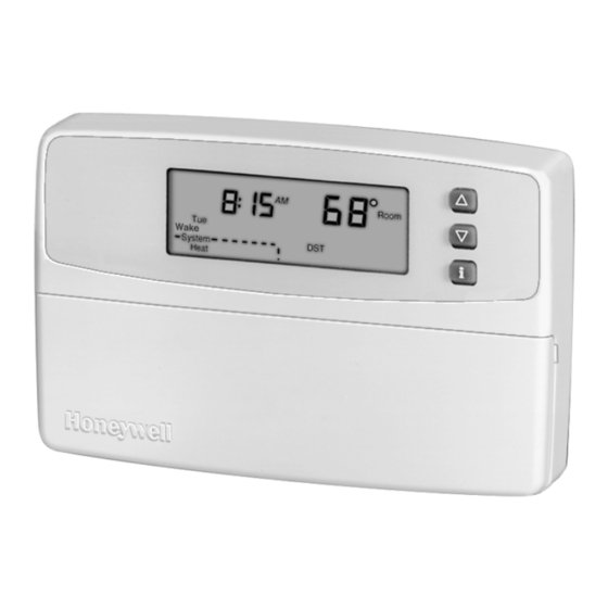
Weekday, Saturday and Sunday
Programmable Heat and/or Cool
Low Voltage (20 to 30 Vac) Thermostat and Wallplate
Model CT3500/CT3595
Para pedir estas instrucciones en español, llame al 1-800-468-1502.
Pour obtenir ce ode demploi en français, composer le 1-800-468-1502.
Table of Contents
Step 1. Prepare for Installation................................................................................................................................................
Step 2. Remove Old Thermostat.............................................................................................................................................
Step 3. Mount Thermostat Wallplate.......................................................................................................................................
Step 4. Wire Wallplate Terminals ............................................................................................................................................
Step 5. Install the Batteries .....................................................................................................................................................
Step 6. Set Fan Operation Switch........................................................................................................................................... 10
Step 7. Mount the Thermostat ................................................................................................................................................ 11
Step 8. Customize Your Thermostat ....................................................................................................................................... 11
Step 9. Set the Clock .............................................................................................................................................................. 13
Step 10. Programming ............................................................................................................................................................ 14
Step 11. Operating Your Thermostat....................................................................................................................................... 17
Step 12. Set the Fan and System Switches............................................................................................................................ 18
If You Have a Problem ............................................................................................................................................................ 19
Smart Response™ Technology .............................................................................................................................................. 21
Wiring Diagrams ..................................................................................................................................................................... 22
® U.S. Registered Trademark
© 2004 Honeywell International Inc.
All Rights Reserved
Honeywell CT3500/CT3595
PROGRAMMABLE THERMOSTAT
OWNER'S GUIDE
5
6
7
8
9
69-1199-4
Advertisement
Table of Contents

Related Manuals for Honeywell CT3500


Summary of Contents for Honeywell CT3500
-
Page 1: Table Of Contents
Step 12. Set the Fan and System Switches... 18 If You Have a Problem ... 19 Smart Response™ Technology ... 21 Wiring Diagrams ... 22 ® U.S. Registered Trademark © 2004 Honeywell International Inc. All Rights Reserved Honeywell CT3500/CT3595 PROGRAMMABLE THERMOSTAT OWNER’S GUIDE... -
Page 2: Mercury Notice
Total comfort temperature management with Smart Response™ Technology. Congratulations! You made a smart choice by purchasing your new Honeywell thermostat the smart thermostat that; • Keeps you comfortable by automatically calculating exactly when the furnace or air conditioning should go on to have the house at the desired comfort temperature by the time you wake up or return home. - Page 3 DIGITAL DISPLAY SET CURRENT DAY/TIME SETS CURRENT TIME AND DAY RUN PROGRAM RETURNS THERMOSTAT TO NORMAL Set Current OPERATING MODE Program Hold Temp HOLD TEMP SETS A HOLD TEMPERATURE AND ACTIVATES VACATION HOLD FEATURE. SETS DAY OF THE WEEK TIME...
- Page 4 DISPLAYS EITHER CURRENT TIME OF DAY OR PROGRAM TIMES SHOWS WHEN THERMOSTAT IS IN THE PROGRAMMING MODE SHOWS VACATION HOLD DURATION Set Program Hold for SHOWS CURRENT Em Ht DAY OR DAYS BEING PROGRAMMED Aux Ht TueWedThuFriSatSun Days WakeLeaveReturnSleep SHOWS CURRENT...
-
Page 5: Step 1. Prepare For Installation
Baseboard Electric (120/240 line volt) Single Stage Heat Pump Multistage Heat Pumps/Multistage Equipment Compatible with 2-wire Honeywell and Taco zone valves. Not compatible with 3-wire zone valves or 2-wire White Rodgers no. 1361 zone valves. Millivolt system must be heating only. -
Page 6: Step 2. Remove Old Thermostat
Carefully unpack your new thermostat and wallplate. Save package of screws, instructions, and receipt. Remove the cover from the old thermostat. If the cover does not snap off when pulled firmly from the bottom, check for a screw or screws used to lock on the cover. -
Page 7: Step 3. Mount Thermostat Wallplate
Replacing a Thermostat that has Three Wires If you have three wires for a heating only system and can operate the fan using the fan ON switch this thermostat works with your system. However, some hot water (zoned) heating systems also have three wires. Your thermostat will work only if you install an isolating relay on these systems. -
Page 8: Step 4. Wire Wallplate Terminals
Refer to the labels you placed on the wires when you removed the old thermostat (see illustration). Match the letter of your old thermostat wire with the corresponding terminal letter on your new thermostat. Refer to Table 2. -
Page 9: Step 5. Install The Batteries
G, F If both RH and R terminals are present on existing thermostat, remove jumper and connect Rh to R and R to Rc. Do not connect both O and B when wiring to a single stage heat pump. Connect O to O. Tape off B. -
Page 10: Step 6. Set Fan Operation Switch
As a precaution when leaving home for longer than a month, change batteries before leaving to prevent the system from shutting down due to lack of power. Always use fresh alkaline batteries. Nonalkaline batteries do not last as long. They also can leak, causing damage to the thermostat and the wall surface. -
Page 11: Step 7. Mount The Thermostat
ENGAGE TABS AT TOP OF THERMOSTAT AND WALLPLATE. STEP 8. CUSTOMIZE YOUR THERMOSTAT Your Honeywell thermostat comes preset to the most commonly used settings. The settings are: — Gas or oil forced air furnace. — Smart Response technology on. — Temperature °F. - Page 12 System Type (Feature Number 4) System type options are: — 1 = Gravity or steam system. — 3 = Hot water, high efficiency furnace (90% or better), or single stage heat pump. — 6 = Gas or oil forced air furnace (preset). —...
-
Page 13: Set Current Day And Time
Time Format (Feature Number 16) Time format options are: — 0 = 12-hour clock (preset). — 1 = 24-hour clock. To change time format: Press once. Press to return to main display. Program Factory Set Function (Feature Number 37) Do not change this setting. STEP 9. -
Page 14: Step 10. Programming
STEP 10. PROGRAMMING The keyboard is located behind the thermostat cover. The three most frequently used keys are near the display. Pressing displays the current temperature settings. Pressing the thermostat displays day, time, program period, temperature and system settings. There is an individual key for each of the four program periods: —The program period when you want the house at a comfortable temperature when you get up and while you... - Page 15 Period Default Setting Wake Time (6:00AM) Heat (70°F/21°C) Cool (78°F/25.5°C) Leave Time (8:00AM) Heat (62°F/16.5°C) Cool (85°F/29.5°C) Return Time (6:00PM) Heat (70°F/21°C) Cool (78°F/25.5°C) Sleep Time (10:00PM) Heat (62°F/16.5°C) Cool (82°F/28°C) Your heating setpoints cannot be higher than 90°F (32°C) or lower than 40°F (4.5°C). Your cooling setpoints cannot be higher than 99°F (35°C) or lower than 45°F (7°C).
- Page 16 Heat/Cool Press to switch between heating and cooling setpoints. Settings NOTE: Program times are the same for heating and cooling. Press until the display shows the desired temperature setpoint. Press Sleep Leave Return Program Saturday and Sunday Repeat each step in Program Weekdays for Saturday and Sunday. Press when the entire week is programmed.
-
Page 17: Step 11. Operating Your Thermostat
STEP 11. OPERATING YOUR THERMOSTAT Change Temperature Setting Until the Next Program Period (Temporary Change) Press until the screen shows the desired temperature setting. NOTE: The temporary temperature setting is displayed for about 3 seconds and then the room temperature is displayed. -
Page 18: Step 12. Set The Fan And System Switches
Fan Auto: Normal setting for most homes. The equipment controls the fan operation. Then set the system Heat: The thermostat controls your heating system. switch. Off: Both the heating and air conditioning systems are off. Cool: The thermostat controls your air conditioning system. 69-1199—4 Auto Auto Heat Cool... -
Page 19: If You Have A Problem
Make sure the batteries are fresh and installed correctly. • Make sure the thermostat is mounted and latched on the wallplate. Mount and latch the thermostat on the wallplate if it is not. • Make sure the temperature setpoints are: —40°F to 90°F (4.5°C to 32°C) for heating. -
Page 20: Toll-Free Customer Assistance
Temperature changes occur at the wrong times. Toll-Free Customer Assistance Please read and follow the provided instructions for this thermostat. For additional information, go to www.honeywell.com/yourhome or call Honeywell Customer Care at 1-800-468-1502. Before calling, please have the following information available: •... -
Page 21: Smart Response™ Technology
SMART RESPONSE™ TECHNOLOGY Your thermostat is actually a small computer. The Smart Response technology calculates the correct time of day to turn on your heating or cooling system. Smart Response technology considers the following information. • Air temperature. • Wall temperature. -
Page 22: Wiring Diagrams
WIRING DIAGRAMS 2-WIRE HEAT-ONLY (JUMPER INTACT) THERMOSTAT RC O W Y HEATING RELAY OR VALVE COIL 1 POWER SUPPLY. PROVIDE DISCONNECT MEANS AND OVERLOAD PROTECTION AS REQUIRED. 3-WIRE HEAT ONLY WITH FAN (JUMPER INTACT) THERMOSTAT RC O W Y HEATING... - Page 23 RELAY VALVE COIL 1 POWER SUPPLY. PROVIDE DISCONNECT MEANS AND OVERLOAD PROTECTION AS REQUIRED. Notice: This thermostat is a Class B digital apparatus that complies with Canadian Radio Interference Regulations, CRC c. 1374. COOLING CONTACTOR COIL M10619 5-WIRE HEAT/COOL WITH DAMPER...
-
Page 24: Limited One-Year Warranty
Golden Valley, MN 55422-3992 This warranty does not cover removal or reinstallation costs. This warranty shall not apply if it is shown by Honeywell that the defect or malfunction was caused by damage which occurred while the product was in the possession of a consumer.
Need help?
Do you have a question about the CT3500 and is the answer not in the manual?
Questions and answers