Table of Contents
Advertisement
BEFORE SERVICING ...................................................................................................... INSIDE FRONT COVER
WARNING TO SERVICE PERSONNEL ................................................................................................................ 1
MICROWAVE MEASUREMENT PROCEDURE ................................................................................................... 2
FOREWORD AND WARNING ............................................................................................................................... 3
PRODUCT SPECIFICATIONS .............................................................................................................................. 4
GENERAL INFORMATION ................................................................................................................................... 4
OPERATION .......................................................................................................................................................... 6
TROUBLESHOOTING GUIDE .............................................................................................................................. 9
TEST PROCEDURE ............................................................................................................................................ 10
TOUCH CONTROL PANEL ................................................................................................................................. 16
COMPONENT REPLACEMENT AND ADJUSTMENT PROCEDURE ................................................................ 20
PICTORIAL DIAGRAM ........................................................................................................................................ 26
CONTROL PANEL CIRCUIT ............................................................................................................................... 27
PRINTED WIRING BOARD ................................................................................................................................. 28
PARTS LIST ........................................................................................................................................................ 29
PACKING AND ACCESSORIES ......................................................................................................................... 31
SHARP CORPORATION
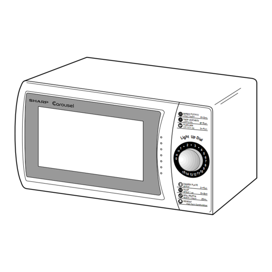
SERVICE MANUAL
MODELS
BAKE D POTA TO
COOK 1 medium
4 5
min.
FRESH VEGET ABLES
COOK 2 cups
6 8
min.
POPC ORN
POP 3.5 oz. bag
3 4
min.
2
3
1
4
40
5
20
6
0
7
8
9
10
15
14
11
13
12
In the interest of user-safety the oven should be restored to its original
DINN ER PLAT
E
REHE AT
3 4
min.
SOU P
condition and only parts identical to those specified should be used.
REHE AT 1 cup
6 8
min.
ROLL /MUF FIN
REHE AT 1 medium
20
sec.
DEFR OST
Check chart in Operat
ion Manua l
WARNING TO SERVICE PERSONNEL: Microwave ovens con-
tain circuitry capable of producing very high voltage and
current, contact with following parts may result in a severe,
possibly fatal, electrical shock. (High Voltage Capacitor, High
Voltage Power Transformer, Magnetron, High Voltage Recti-
fier Assembly, High Voltage Harness etc..)
TABLE OF CONTENTS
MICROWAVE OVEN
R-200BK
R-200BW
This document has been published to be used for after
sales service only.
The contents are subject to change without notice.
R-200BK
R-200BW
S1802R200BPW/
Page
Advertisement
Table of Contents

Related Manuals for Sharp R-200BK


Summary of Contents for Sharp R-200BK
-
Page 1: Table Of Contents
R-200BK R-200BW SERVICE MANUAL S1802R200BPW/ MICROWAVE OVEN R-200BK MODELS R-200BW BAKE D POTA TO COOK 1 medium min. FRESH VEGET ABLES COOK 2 cups min. POPC ORN POP 3.5 oz. bag min. In the interest of user-safety the oven should be restored to its original... -
Page 2: Precautions To Be Observed Before And During Servicing To Avoid Possible Exposure To Excessive Microwave Energy
Before servicing an operative unit, perform a microwave emission check as per the Microwave Measurement Procedure outlined in this service manual. If microwave emissions level is in excess of the specified limit, contact SHARP ELECTRONICS CORPORATION immediately @1-800-237-4277. If the unit operates with the door open, service person should 1) tell the user not to operate the oven and 2) contact SHARP ELECTRONICS CORPORATION and Food and Drug Administration's Center for Devices and Radiological Health immediately. -
Page 3: Warning To Service Personnel
R-200BK R-200BW WARNING TO SERVICE PERSONNEL Microwave ovens contain circuitry capable of pro- ducing very high voltage and current, contact with following parts may result in a severe, possibly fatal, electrical shock. (Example) High Voltage Capacitor, High Voltage Power Trans- former, Magnetron, High Voltage Rectifier Assem- bly, High Voltage Harness etc.. -
Page 4: Microwave Measurement Procedure
R-200BK R-200BW MICROWAVE MEASUREMENT PROCEDURE A. Requirements: 1) Microwave leakage limit (Power density limit): The power density of microwave radiation emitted by a microwave oven should not exceed 1mW/cm at any point 5cm or more from the external surface of the oven, measured prior to acquisition... - Page 5 MICROWAVE OVEN R-200BK/ R-200BW GENERAL INFORMATION FOREWORD This Manual has been prepared to provide Sharp Electronics Corp. OPERATION Service Personnel with Operation and Service Information for the SHARP MICROWAVE OVEN, R-200BK, R-200BW. It is recommended that service personnel carefully study the entire...
-
Page 6: General Information
R-200BK R-200BW PRODUCT DESCRIPTION SPECIFICATIONS ITEM DESCRIPTION Power Requirements 120 Volts 60 Hertz Single phase, 3 wire grounded Power Consumption 1030W / Approx. 9.0 Amperes Power Output 600 W nominal of RF microwave energy (IEC 705 Test procedure) Operating frequency 2450 MHz Case Dimensions Width 18-1/8"... -
Page 7: Oven Diagram
R-200BK R-200BW OVEN DIAGRAM 1. Oven door with see-through window 2. Safety door latches. 3. Door hinges 4. Door seals and sealing surfaces 5. Turntable motor shaft 6. Removable turntable support 7. Removable turntable 8. Ventilation openings. (Rear) 9. Oven lamp. -
Page 8: Operation
R-200BK R-200BW OPERATION DESCRIPTION OF OPERATING SEQUENCE The following is a description of component functions during box, and then into the cavity where the food is placed to oven operation. be cooked. 5. Upon completion of the cooking time, the power OFF CONDITION transformer, oven lamp, etc. - Page 9 R-200BK R-200BW SCHEMATIC NOTE: CONDITION OF OVEN 1. DOOR CLOSED. 2. LIGHT UP DIAL ON. C/T FUSE MAGNETRON THERMAL CUT-OUT COM. POWER TRANSFORMER N.O. (RY-1) PRIMARY INTERLOCK RELAY MONITOR CAPACITOR CONTROL UNIT SWITCH 0.72 F TURN- OVEN LAMP TABLE MOTOR...
-
Page 10: Troubleshooting Guide
R-200BK R-200BW TURNTABLE MOTOR However, when abnormally high temperatures are reached within the magnetron, the thermal cut-out will open at 257˚F The turntable motor rotates the turntable located on the (125˚C), causing the oven to shut down. bottom of the oven cavity, so that the food on the turntable is cooked evenly. -
Page 11: Test Procedure
R-200BK R-200BW CK = Check / RE = Replace A B C D E F F G H TEST PROCEDURE RE CK RE RE CK CK CK CK K POSSIBLE CAUSE DEFECTIVE PARTS PROBLEM CONDITION Home fuse blows when power cord is plugged into wall receptacle. - Page 12 R-200BK R-200BW TEST PROCEDURES PROCEDURE COMPONENT TEST LETTER HIGH VOLTAGES ARE PRESENT DURING THE COOK CYCLE, SO EXTREME CAUTION SHOULD BE OBSERVED. Power output of the magnetron can be measured by performing a water temperature rise test. This test should only be used if above tests do not indicate a faulty magnetron and there is no defect in the following components or wiring: silicon rectifier, high voltage capacitor and power transformer.
- Page 13 R-200BK R-200BW TEST PROCEDURES PROCEDURE COMPONENT TEST LETTER 8. Run the oven and check all functions. NOTE: Be sure to use an ohmmeter that will supply a forward bias voltage of more than 6.3 volts. HIGH VOLTAGE CAPACITOR TEST 1. Disconnect the power supply cord, and then remove outer case.
- Page 14 R-200BK R-200BW TEST PROCEDURES PROCEDURE COMPONENT TEST LETTER the door closed. If improper operation is indicated, replace the door sensing switch. 5. Reconnect all leads removed from components during testing. 6. Reinstall the outer case (cabinet). 7. Reconnect the power supply cord after the outer case is installed.
- Page 15 R-200BK R-200BW TEST PROCEDURES PROCEDURE COMPONENT TEST LETTER If the C/T fuse is blown by improper switch operation, the C/T fuse and monitor switch must be replaced with "C/T fuse and monitor switch assembly" part number FFS-BA020WRK0, even if the monitor switch operates normally.
- Page 16 R-200BK R-200BW TEST PROCEDURES PROCEDURE COMPONENT TEST LETTER RELAY TEST 1. Disconnect the power supply cord and then remove outer case. 2. Open the door and block it open. 3. Discharge high voltage capacitor. 4. Disconnect the leads to the primary of the power transformer.
- Page 17 R-200BK R-200BW TEST PROCEDURES PROCEDURE COMPONENT TEST LETTER 6) Reconnect all leads removed from components during testing. 7) Re-install the outer case (cabinet). 8) Reconnect the power supply cord after the outer case is installed. 9) Run the oven and check all function.
-
Page 18: Control Panel Assembly
R-200BK R-200BW CONTROL PANEL ASSEMBLY OUTLINE OF CONTROL PANEL Control Unit 4) ACL Control unit consists of LSI, power source circuit, synchro- A circuit to generate a signals which resets the LSI to the nizing signal circuit, ACL circuit, buzzer circuit, encoder initial state when power is supplied. - Page 19 R-200BK R-200BW DESCRIPTION OF LSI LSI(IZA860DR) The I/O signal of the LSI(IZA860DR) are detailed in the following table. Pin No. Signal Description Auto clear terminal. Signal is input to reset the LSI to the initial state when power is applied. Temporarily set to “L”...
- Page 20 R-200BK R-200BW Pin No. Signal Description Segment data signal. Signal is input to the cathodes of the light-emitting diodes (LD1-LD4, LD6-LD9, LD11- LD14, LD16-LD18 and LD19). 23-25 D6-D7 Segment data signal. Signal is input to the cathodes of all light-emitting diodes (LD1-D20).
-
Page 21: Touch Control Panel
R-200BK R-200BW SERVICING 1. Precautions for Handling Electronic Components 5) Re-connect the power supply cord after the outer case This unit uses CMOS LSI in the integral part of the is installed. circuits. When handling these parts, the following 6) Run the oven and check all function. -
Page 22: Component Replacement And Adjustment Procedure
3. The door gasket or seal is damaged. 4. If the outer case (cabinet) is not fitted. WARNING FOR WIRING To prevent an electric shock, take the following pre- 3) Sharp edge: cautions. Bottom plate, Oven cavity, Waveguide flange, 1. Before wiring, Chassis support and other metallic plate. - Page 23 R-200BK R-200BW CAUTION: 1. DISCONNECT OVEN FROM POWER SUP- NOTE: When replacing the outer case, the 2 special PLY BEFORE REMOVING OUTER CASE. Torx screws must be reinstalled in the same 2. DISCHARGE THE HIGH VOLTAGE CA- locations. PACITOR BEFORE TOUCHING ANY OVEN COMPONENTS OR WIRING.
-
Page 24: Control Panel Assembly Removal
Re-install 3. Turn the oven over. 1. Remove the any sharp edges on the turntable motor 4. Cut the four (4) bridges holding the turntable motor cover cover and the bottom plate with the cutting pliers. to the bottom plate with the cutting pliers as shown in 2. -
Page 25: Pictorial Diagram
R-200BK R-200BW COOLING FAN MOTOR REMOVAL 15. Remove the two (2) screws holding the fan motor to the REMOVAL fan duct. 1. Disconnect the power supply cord and remove outer case. 16. Now, the fan motor is free. 2. Open the door and block it open. - Page 26 R-200BK R-200BW 8-2. Then pull out the switch while pushing the plunger of the 5. Re-connect wire leads to the control unit. Refer to switch again. chapter "Pictorial Diagram". 8-3. Now the secondary interlock switch is free. 6. Make sure that monitor switch is operating properly and 9.
- Page 27 R-200BK R-200BW 5. Release choke cover from door panel. microwave energy from oven cavity during cook 6. Now choke cover is free. cycle. This function does not require that door be air- tight, moisture (condensation)-tight or light-tight. Therefore, occasional appearance of moisture, light...
- Page 28 R-200BK R-200BW...
- Page 29 R-200BK R-200BW 3.3k /35v 4.7k 4.7k 4.7k /50v /16v HZ4C3 M34225M1 4.7k 1/2w HZ6C3 ZD4-5 1/2w DTA143E /50v /25v 1000 HZ12A1 ZD1-2 DTA143E (JA) (JD) DTA143E 100k DTA143E 100k 10G471K1 VRS1...
-
Page 30: Printed Wiring Board
R-200BK R-200BW LD10 LD11 LD12 LD13 LD14 LD15 LD16 LD20 LD17 LD19 LD18 (JD) FUSE1 WH-1 CN-A RED (J1) VRS1 Figure S-3. Printed Wiring Board... -
Page 31: Parts List
Turntable motor (Interchangeable) 1-11 RTHM-A078WRE0 Thermal cut-out 125˚C 1-12 RTRN-A560WRE0 Power transformer CABINET PARTS 2- 1 GCABUA657WRP0 Outer case cabinet [R-200BK] 2- 1 GCABUA659WRP0 Outer case cabinet [R-200BW] 2- 2 GDAI-A304WRP0 Bottom plate 2- 3 GLEGPA074WRE0 Foot CONTROL PANEL PARTS... - Page 32 XOTSD40P12RV0 Screw : 4mm x 12mm 7- 8 XOTSD40P12000 Screw : 4mm x 12mm 7- 9 XOTSE40P08000 Screw : 4mm x 8mm [R-200BW] 7- 9 XOTSF40P08000 Screw : 4mm x 8mm [R-200BK] 7-10 LX-CZA071WRE0 Special screw (Torx tamper proof screw)
-
Page 33: Packing And Accessories
To have your order filled promptly and correctly, please furnish the following information. 1. MODEL NUMBER 2. REF. NO. 3. PART NO. 4. DESCRIPTION Order Parts from the authorized SHARP parts Distributor for your area. Defective parts required return should be returned as indicated in the Service Policy. - Page 34 R-200BK R-200BW OVEN AND CABINET PARTS 7-10 7-10 4-10 4-14 4-11 1-11 4-16 1-10 4-15 1-12 4-13 4-12...
- Page 35 R-200BK R-200BW CONTROL PANEL PARTS 3-1-4 3 - 2 3-1-2 3-1-1 3-1-3 3 - 3 DOOR PARTS 3 - 1 MISCELLANEOUS Actual wire harness may be different than illustration.
- Page 36 No part of this publication may be reproduced, stored in a retrieval systems, or transmitted in any form or by any means, electronic, mechanical, pho- tocopying, recording, or otherwise, without prior written permission of the publisher. '98 SHARP CORP. (1S2.530E) Printed in U.S.A...
Need help?
Do you have a question about the R-200BK and is the answer not in the manual?
Questions and answers