Table of Contents
Advertisement
Quick Links
CHAPTER 1. BEFORE SERVICING
CHAPTER 2. WARNING TO SERVICE PERSONNEL
CHAPTER 3. PRODUCT SPECIFICATIONS
CHAPTER 4. APPEARANCE VIEW
CHAPTER 5. OPERATION SEQUENCE
CHAPTER 6. FUNCTION OF IMPORTANT COMPO-
NENTS
CHAPTER 7. TROUBLESHOOTING GUIDE
SHARP CORPORATION
SERVICE MANUAL
MODELS
In the interest of user-safety the oven should be restored to its
original condition and only parts identical to tho
should be used.
CONTENTS
CHAPTER 8. TEST PROCEDURES
CHAPTER 9. TOUCH CONTROL PANEL ASSEMBLY
CHAPTER 10. COMPONENT REPLACEMENT AND
ADJUSTMENT PROCEDURE
CHAPTER 11. MICROWAVE MEASUREMENT
CHAPTER 12. CIRCUIT DIAGRAMS
Parts List
S8313R20APVNS
MICROWAVE OVEN
R-20A1(S)VN
R-21A1(S)VN
This document has been published to be used
for after sales service only.
The contents are subject to change without notice.
R-20A1(S)VN
Advertisement
Table of Contents

Related Manuals for Sharp R-20A1(S)VN


Summary of Contents for Sharp R-20A1(S)VN
- Page 1 R-20A1(S)VN SERVICE MANUAL S8313R20APVNS MICROWAVE OVEN R-20A1(S)VN MODELS R-21A1(S)VN In the interest of user-safety the oven should be restored to its original condition and only parts identical to tho should be used. CONTENTS CHAPTER 1. BEFORE SERVICING CHAPTER 8. TEST PROCEDURES CHAPTER 2.
-
Page 2: Table Of Contents
R-20A1(S)VN CONTENTS CHAPTER 1. BEFORE SERVICING CHAPTER 10. COMPONENT REPLACEMENT AND ADJUSTMENT PROCEDURE GENERAL IMPORTANT INFORMATION....1-1 CAUTION MICROWAVE RADIATION .....1-1 BEFORE OPERATING ........... 10-1 WARNING ..............1-1 OUTER CASE REMOVAL ..........10-1 HIGH VOLTAGE TRANSFORMER RE- CHAPTER 2. WARNING TO SERVICE PERSONNEL MOVAL ................ -
Page 3: Chapter 1. Before Servicing
R-20A1(S)VN CHAPTER 1. BEFORE SERVICING R218L(W) [1] GENERAL IMPORTANT INFORMATION This Manual has been prepared to provide Sharp Corp. Service engineers with Operation and Service Information. isfactory customer ser- vice. WARNING: THIS APPLIANCE MUST BE EARTHED IMPORTANT THE WIRES IN THIS MAINS LEAD ARE COLOURED IN ACCORDANCE WITH THE FOLLOWING CODE:... -
Page 4: Chapter 2. Warning To Service Personnel
R-20A1(S)VN CHAPTER 2. WARNING TO SERVICE PERSONNEL R218L(W) Microwave ovens contain circuitry capable of producing very high voltage and current, contact with any part of the high voltage circuit will result in ltage harness. REMEMBER TO CHECK 3D REMEMBER TO CHECK 4R 1) Disconnect the supply. -
Page 5: Chapter 3. Product Specifications
R-20A1(S)VN CHAPTER 3. PRODUCT SPECIFICATIONS R218L(W) 220 Volts Power Requirements 50 Hertz Single phase, 3 wire earthed Power Consumption 1.25 kW 800 watts nominal of RF microwave energy (measured by method of IEC 60705) Power Output Operating frequency 2450 MHz... -
Page 6: Chapter 4. Appearance View
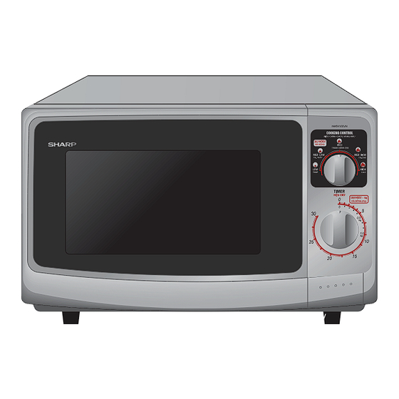
R-20A1(S)VN CHAPTER 4. APPEARANCE VIEW R218L(W) [1] OVEN 1. Ventilation openings 2. Oven lamp 3. Door hinges 4. Door safety latches 5. See through door 6. Door seals sealing surfaces 7. Coupling 8. Control panel 9. Waveguide cover 10. Power supply cord 11. -
Page 7: Chapter 5. Operation Sequence
R-20A1(S)VN CHAPTER 5. OPERATION SEQUENCE R218L(W) [1] OFF CONDITION The timer stops to indicate how much cooking time remains. 7. MONITOR SWITCH CIRCUIT 1. When the timer knob is at “0”, the oven is OFF condition. The monitor switch is mechanically controlled by oven door, and 2. -
Page 8: Chapter 6. Function Of Important Compo
R-20A1(S)VN CHAPTER 6. FUNCTION OF IMPORTANT COMPONENTS R218L(W) [1] DOOR OPEN MECHANISM [6] TEMPERATURE FUSE 150C (OVEN) The door is opened by pushing the open button on the control panel, The temperature fuse located on the top of the oven cavity is designed refer to the Figure D-1. -
Page 9: Chapter 7. Troubleshooting Guide
R-20A1(S)VN CHAPTER 7. TROUBLESHOOTING GUIDE R218L(W) [1] FOREWORD When troubleshooting the microwave oven, it is helpful to follow the IMPORTANT: Sequence of Operation in performing the checks. Many of the possible If the oven becomes inoper ative because of a blown fuse T6.3A in the monitored latch switch - relay RY1 - timer switch - monitor switch cir- tests are given a procedure letter which will be found in the “Test Pro-... -
Page 10: Chapter 8. Test Procedures
R-20A1(S)VN CHAPTER 8. TEST PROCEDURES R218L(W) [1] Procedure A: MAGNETRON (MG) TEST NEVER TOUCH ANY PART IN THE CIRCUIT WITH YOUR HAND OR AN INSULATED TOOL WHILE THE OVEN IS IN OPERATION. CARRY OUT 3D CHECKS. r should show a reading of less than 1 ohm. -
Page 11: Procedure B: High Voltage Transformer Test
R-20A1(S)VN 1000g 1000g 1000g T1 C T2 C [2] Procedure B: HIGH VOLTAGE TRANSFORMER TEST WARNING: High voltages and large currents are present at the secondary winding and filament winding of the power transformer. It is very dangerous to work near this part when the oven is on. NEVER make any voltage measurements of the high-voltage cir- cuits, including the magnetron filament. -
Page 12: Procedure F: Temperature Fuse Test
R-20A1(S)VN If incorrect readings are obtained, make the necessary switch adjustment or replace the switch. CARRY OUT 4R CHECKS. [6] Procedure F: TEMPERATURE FUSE TEST CARRY OUT 3D CHECKS. Disconnect the leads from the terminals of the temperature fuse. Then using an ohmmeter, make a continuity test across the two terminals as described in the below. - Page 13 R-20A1(S)VN 2. TIMER - MOTOR Disconnect the leads from terminals described at following table. Connect an ohmmeter across the timer motor winding, terminals are described at following table, and check that a reading of resistance described at following table is indicated.
-
Page 14: Chapter 10. Component Replacement And Adjustment Procedure Before Operating
3) If the door is not closed. 2) Door hinge, support or latch hook is damaged. WARNING FOR WIRING To prevent an electric shock, take the following manners. 3) Sharp edge: 1. Before wiring, plate. 1) Disconnect the power supply cord. -
Page 15: High Voltage Transformer Removal
R-20A1(S)VN [3] HIGH VOLTAGE TRANSFORMER REMOVAL 1. CARRY OUT 3D CHECKS. 5. Remove the two (2) screws holding the transformer to bottom plate from below. 2. Disconnect the wire leads (main wire harness and H.V. fuse) from high voltage transformer. -
Page 16: Turntable Motor Removal
3. Lay the oven on it's backside. Remove the turntable motor cover by tom plate. 5. Re-install the turntable motor cover to the bottom plate with one (1) screw. No sharp edges must be evident after removal of the turntable motor cover. TTM packing 5. Disconnect wire leads from turntable motor. -
Page 17: Power Supply Cord Replacement
R-20A1(S)VN [9] POWER SUPPLY CORD REPLACEMENT 1. REMOVAL Power Supply Oven Cavity 1. CARRY OUT 3D CHECKS. Cord Back Plate Screw 2. Remove the single (1) screw holding the green/yellow wire to the oven cavity back plate. 3. Disconnect the leads of the power supply cord from the fuse holder Brown Wire assembly, referring to the Figure C-3(a). -
Page 18: Door Replacement
R-20A1(S)VN 2. After adjustment, check the following. Latch Heads 1. In and out play of door remains less than 0.5mm when in the Latch Hook latched position. First check upper position of latch hook, pushing and pulling upper portion of door toward the oven face. Then check lower portion of the latch hook, pushing and pulling lower portion of the door toward the oven face. - Page 19 R-20A1(S)VN 4. SEALER FILM Upper Oven Hinge shown in Fig. C-7 Sealer film Backing film Slit Choke Adhesive tape Door Panel Lower Oven Hinge Choke Cover Lower Oven Hinge Figure C-6. Door Replacement 10 – 6...
-
Page 20: Chapter 11. Microwave Measurement
R-20A1(S)VN CHAPTER 11. MICROWAVE MEASUREMENT R218L(W) After adjustment of door latch switches, monitor switch and door are completed individually or collectively, the following leakage test must be per- microwave oven. REQUIREMENT The safety switch must prevent microwave radiation emission in excess of 5mW/cm at any point 5cm or more from external surface of the oven. -
Page 21: Chapter 12. Circuit Diagrams
R-20A1(S)VN CHAPTER 12. CIRCUIT DIAGRAMS R218L(W) [1] Oven Schematic SCHEMATIC NOTE: CONDITION OF OVEN 1. DOOR CLOSED. Figure O-1 Oven Schematic-OFF Condition SCHEMATIC NOTE: CONDITION OF OVEN 1. DOOR CLOSED. 2. COOKING TIME PROGRAMMED. Figure O-2 Oven Schematic-ON Condition 12 – 1... -
Page 22: Pictorial Diagram (Figure S-1)
R-20A1(S)VN [2] Pictorial Diagram (Figure S-1) Figure S-1. Pictorial Diagram 12 – 2... -
Page 23: Parts List
OVEN CAVITY ADDITIONAL LABEL TRAY PAD ASSY (CPADBA287WRKZ) PACKING CASE Not replaceable items. SPAKCF427WREZ [R-20A1(S)VN] SPAKCF427WREZ [R-21A1(S)VN] SHARP CORPORATION This document has been published to be used for after sales service only. The contents are subject to change without notice. - Page 24 R-20A1(S)VN [1] OVEN PARTS 1-10 4-11 1-13 1-12 4-13 7-10 4-12 4-16 4-10 4-14 4-17 1-11 1-14 4-15 7-11 7-11...
- Page 25 QFS CA027WRZZ Fuse T6 3A Fuse T6.3A 1-14 QFS-IA016WRZZ High voltage fuse 0.6A 1-14 QFS-IA004WRE0 High voltage fuse 0.6A (Interchangable) CABINET PARTS GCABUA966WRPZ Outer case cabinet [R-20A1(S)VN] GCABUB220WRPZ Outer case cabinet GDAI-A459WRWZ Bottom plate GLEGPA104WREZ Foot OVENPARTS PHOK-A176WRFZ Latch hook LBNDKA168WRPZ2...
- Page 26 R-20A1(S)VN [2] DOOR AND CONTROL PANEL PARTS Actual wire harness may be different than illustration.
- Page 27 HPNLCC294WRTZ Control panel JBTN-B256WRTZ Open button JKNBKA859WRTZ Timer knob JKNBKA861WRTZ Vari knob MSPRCA050WRE0 Button spring TLABMB468WRRZ Panel sheet [R-20A1(S)VN] TLABMB467WRRZ Panel sheet [R-21A1(S)VN] XEPS730P08XS0 Screw; 3mm x 10mm DOOR PARTS FDORFA397WRTZ Door panel assembly GWAKPB231WRTZ Door frame HPNL-A821WRRZ Door screen...
- Page 28 R-20A1(S)VN COPYRIGHT © 2006 BY SHARP CORPORATION ALL RIGHTS RESERVED. No part of this publication may be reproduced, stored in retrieval systems, or transmitted in anyform or by any means, electronic, mechanical, photocopying, re- cording, or other wise, without prior written permission...
Need help?
Do you have a question about the R-20A1(S)VN and is the answer not in the manual?
Questions and answers