Table of Contents
Advertisement
CAUTION, MICROWAVE RADIATION ................................................................. INSIDE FRONT PAGE
WARNING ................................................................................................................................................. 1
SERVICING ............................................................................................................................................. 2
PRODUCT SPECIFICATIONS ................................................................................................................. 5
GENERAL INFORMATION ....................................................................................................................... 5
APPEARANCE VIEW .............................................................................................................................. 6
OPERATION SEQUENCE ........................................................................................................................ 7
FUNCTION OF IMPORTANT COMPONENTS ....................................................................................... 8
TROUBLESHOOTING GUIDE ................................................................................................................. 9
TEST PROCEDURE .............................................................................................................................. 10
CONTROL PANEL ASSEMBLY ............................................................................................................ 15
COMPONENT REPLACEMENT AND ADJUSTMENT PROCEDURE .................................................. 18
MICROWAVE MEASUREMENT ........................................................................................................... 23
TEST DATA AT A GLANCE .................................................................................................................. 24
WIRING DIAGRAM ................................................................................................................................ 25
PICTORIAL DIAGRAM .......................................................................................................................... 26
CONTROL PANEL CIRCUIT .................................................................................................................. 27
PRINTED WIRING BOARD .................................................................................................................... 28
PARTS LIST .......................................................................................................................................... 29
SERVICE MANUAL
MODELS
In interests of user-safety the oven should be restored to its original
condition and only parts identical to those specified should be used.
TABLE OF CONTENTS
SHARP CORPORATION
MICROWAVE OVEN
R-209(IN)
R-209(W)
R-209(Y)
R-209(IN)
R-209(W)
R-209(Y)
S3408R209PHW/
Page
Advertisement
Table of Contents

Related Manuals for Sharp R-209FW


Summary of Contents for Sharp R-209FW
-
Page 1: Table Of Contents
COMPONENT REPLACEMENT AND ADJUSTMENT PROCEDURE ..........18 MICROWAVE MEASUREMENT ......................23 TEST DATA AT A GLANCE ........................24 WIRING DIAGRAM ..........................25 PICTORIAL DIAGRAM .......................... 26 CONTROL PANEL CIRCUIT ........................27 PRINTED WIRING BOARD ........................28 PARTS LIST ............................29 SHARP CORPORATION... -
Page 2: Caution Microwave Radiation
R-209(IN) R-209(W) R-209(Y) CAUTION MICROWAVE RADIATION Personnel should not be exposed to the microwave energy which may radiate from the magnetron or other microwave generating devices if it is improperly used or connected. All input and output microwave connections, waveguides, flanges and gaskets must be secured. -
Page 3: Warning
MICROWAVE OVEN R-209(IN)/ R-209(W)/ R-209(Y) GENERAL INFORMATION GENERAL IMPORTANT INFORMATION This Manual has been prepared to provide Sharp Corp. Service engineers with Operation and Service Information. APPEARANCE VIEW It is recommended that service engineers carefully study the entire text of this manual, so they will be qualified to render satisfactory customer service. - Page 4 Sharp beveelt ten sterkste aan dat, voor zover mogelijk, defecten worden opgespoord wanneer de stekker uit het Wanneer alle reparaties zijn uitgevoerd en de oven weer in stopcontact is gehaald.
- Page 5 är kallt utför Du 3 steg kontroller och kontrollerar anslutningarna till varje enskild komponent på nytt. Sharp rekommenderar att felsökning sker med strömmen fränkopplad. Ibland kan det var nödvändigt att koppla på När all service är klar och ugnen ihopskruvad skall ugnens strömmen efter det att höljet avlägsnats, utför da 3 Steg...
- Page 6 Sharp raccomanda, nei limiti del possibile, che la ricerca dei guasti avvenga in assenza di alimentazione elettrica. In alcuni casi tuttavia, può essere necessario alimentare Dopo aver portato a termine le operazioni di manutenzione l'apparecchio dopo aver rimosso la scatola esterna.
-
Page 7: General Information
R-209(IN) R-209(W) R-209(Y) PRODUCT DESCRIPTION SPECIFICATION ITEM DESCRIPTION Power Requirements 230 Volts 50 Hertz Single phase, 3 wire earthed Power Consumption 1.18 kW Power Output 800 W nominal of RF microwave energy (measured by method of IEC 60705) Operating fequency 2450 MHz Case Dimensions Width 460 mm... -
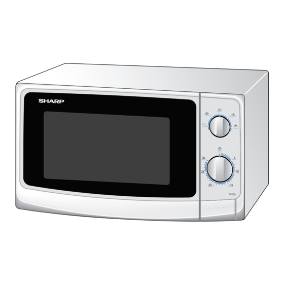
Page 8: Appearance View
R-209(IN) R-209(W) R-209(Y) APPEARANCE VIEW OVEN Turntable Roller stay 1. Control panel 8. Door hinges 2. Door opening button 9. Door seals and sealing surfaces Seal packing 3. Waveguide cover 10.Oven lamp 4. Seal packing 11.Ventilation openings 5. Oven cavity 12.Outer case 6. -
Page 9: Operation Sequence
R-209(IN) R-209(W) R-209(Y) OPERATION SEQUENCE OFF CONDITION motor TTM, timer motor TM, fan motor FM, oven lamp OL and control unit are cut off when the contacts 1. When the timer knob is at " ", the oven is OFF (COM-NO) of the monitored latch switch SW1 and condition. -
Page 10: Function Of Important Components
R-209(IN) R-209(W) R-209(Y) FUNCTION OF IMPORTANT COMPONENTS DOOR OPEN MECHANISM If the food load is overcooked, by either error in cook time or defect in the control unit, the temperature fuse will open. The door is opened by pushing the open button on the Under normal operation, the temperature fuse remains control panel, refer to the Figure D-1. -
Page 11: Troubleshooting Guide
R-209(IN) R-209(W) R-209(Y) TROUBLESHOOTING GUIDE When troubleshooting the microwave oven, it is helpful IMPORTANT: If the oven becomes inoperative because to follow the Sequence of Operation in performing the of a blown fuse F1 T6.3A in the monitored checks. Many of the possible causes of trouble will latch switch SW1 - timer switch - monitor require that a specific test be performed. - Page 12 R-209(IN) R-209(W) R-209(Y) TEST PROCEDURES PROCEDURE COMPONENT TEST LETTER MAGNETRON TEST NEVER TOUCH ANY PART IN THE CIRCUIT WITH YOUR HAND OR AN INSULATED TOOL WHILE THE OVEN IS IN OPERATION. CARRY OUT 3D CHECKS. Isolate the magnetron from the high voltage circuit by removing all leads connected to the filament terminal.
- Page 13 R-209(IN) R-209(W) R-209(Y) TEST PROCEDURES PROCEDURE COMPONENT TEST LETTER Room temperature ....... To = 21˚C Initial temperature ....T1 = 11°C Temperature after (52 + 3) = 55 sec..............T2 = 21°C Temperature difference Cold-Warm (∆T = T2 - T1) ..........∆T = 10°C Measured output power The equation is “P = 80 x ∆T”...
- Page 14 R-209(IN) R-209(W) R-209(Y) TEST PROCEDURES PROCEDURE COMPONENT TEST LETTER HIGH VOLTAGE CAPACITOR TEST CARRY OUT 3D CHECKS. A. Isolate the high voltage capacitor from the circuit. B. Continuity check must be carried out with measuring instrument which is set to the highest resistance range.
- Page 15 R-209(IN) R-209(W) R-209(Y) TEST PROCEDURES PROCEDURE COMPONENT TEST LETTER NOISE FILTER Using an ohmmeter, check between the terminals as described in the following table. FUSE T6.3A MEASURING POINTS INDICATION OF OHMMETER NOISE SUPPRESSION COIL Between N and L Open circuit LINE CROSS CAPACITOR Between terminal N and WHITE Short circuit...
- Page 16 R-209(IN) R-209(W) R-209(Y) TEST PROCEDURES PROCEDURE COMPONENT TEST LETTER CONTROL UNIT TEST CAUTION: DO NOT TOUCH THE ELECTRICAL PARTS AND THE PRINTED WIRING BOARD TO PREVENT AN ELECTRIC SHOCK. BECAUSE THE CONTROL UNIT IS “ TRANSLESS CIRCUIT ” AND ALL ELECTRICAL PARTS ARE USED AT A.C. LINE VOLTAGE. The control unit consists of circuits including semiconductors such as LSI, etc.
- Page 17 R-209(IN) R-209(W) R-209(Y) CONTROL UNIT ASSEMBLY OUTLINE OF CONTROL UNIT The control unit consists of the following circuits as shown in the control unit circuit. The principal functions of these circuits and their related signals are explained below. Control Unit Control unit consists of LSI, reset circuit, power source circuit, relay circuit and synchronizing signal circuit.
- Page 18 R-209(IN) R-209(W) R-209(Y) DESCRIPTION OF LSI The I/O signal of the LSI are detailed in the following table. Pin No. Signal Description Power source voltage: 5V. Connected to 5V. Power source voltage: 0V. Connected to 0V. Internal clock oscillation frequency input setting. The internal clock frequency is generated by connecting the capacitor and resistor to XIN.
- Page 19 R-209(IN) R-209(W) R-209(Y) SERVICING As for the sensor-related controls of the touch 1. Precautions for Handling Electronic Components control panel, checking them is possible if the This unit uses CMOS LSI in the integral part of the dummy resistor(s) with resistance equal to that circuits.
-
Page 20: Component Replacement And Adjustment Procedure
Please refer to ‘OVEN PARTS, CABINET PARTS, CONTROL PANEL PARTS, DOOR PARTS’, when carrying out any of the following removal procedures: WARNING FOR WIRING and Oven cavity. To prevent an electric shock, take the following 3) Sharp edge: manners. Oven cavity, Waveguide flange, other metallic 1. Before wiring, plate. -
Page 21: Control Panel Assembly
R-209(IN) R-209(W) R-209(Y) MAGNETRON REMOVAL 1. CARRY OUT 3D CHECKS. 5. Now, the magnetron is free. 2. Disconnect the wire leads from magnetron. CAUTION: WHEN REPLACING THE MAGNETRON, 3. Remove the three (3) screws holding the magnetron to BE SURE THE R.F. GASKET IS IN PLACE the waveguide. - Page 22 R-209(IN) R-209(W) R-209(Y) TURNTABLE MOTOR REMOVAL Removal Re-install 1. Re-install the TTM packing. 1. Disconnect the oven from the power supply. 2. Re-install the turntable motor with theTTM packing 2. Remove the turntable and turntable support from the with the single (1) screw. oven cavity.
- Page 23 R-209(IN) R-209(W) R-209(Y) POWER SUPPLY CORD REPLACEMENT Re-install Removal 1. Insert the moulding cord stopper of power supply cord 1. CARRY OUT 3D CHECKS. into the square hole of the rear cabinet, referring to the 2. Remove the single (1) screw holding the green/yellow Figure C-3 (b).
- Page 24 R-209(IN) R-209(W) R-209(Y) After adjustment, check the following. door) should be less than 0.5mm. 1. In and out play of door remains less than 0.5mm when 2. The monitored latch switch, latch switch interrupt the in the latched position. First check upper position of circuit before the door can be opened.
-
Page 25: Microwave Measurement
R-209(IN) R-209(W) R-209(Y) SEALER FILM Sealer film Backing film Installation Adhesive tape 1. Put the adhesive tape on the backing film of the sealer film as shown in Fig. C-7. 2. Tear the backing film by pulling the adhesive tape. 3. -
Page 26: Test Data At A Glance
R-209(IN) R-209(W) R-209(Y) TEST DATA AT A GLANCE PARTS SYMBOL VALUE / DATA Fuse T6.3A 250V High voltage fuse 0.6A 5kV Temperature fuse (OVEN) 120°C Oven lamp 240 V 25W High voltage capacitor 0.91µF AC 2100V Filament < 1Ω / Filament – chassis ∞ ohm. Magnetron High voltage transformer Filament winding <... - Page 27 R-209(IN) R-209(W) R-209(Y) SCHEMATIC NOTE: CONDITION OF OVEN 1. DOOR CLOSED. NOTE: " " indicates components with potential above 250V. NOISE FILTER SW1: MONITORED LATCH SWITCH FUSE T6.3A TEMPERATURE FUSE (OVEN) Figure O-1 Oven Schematic-OFF Condition SCHEMATIC NOTE: CONDITION OF OVEN 1.
- Page 28 R-209(IN) R-209(W) R-209(Y)
- Page 29 R-209(IN) R-209(W) R-209(Y) 4.7k IC-1 4.7k – 4.7k 10kB 0.1µ/50v 2SA1267Y HZ4C3 10µ/25v 1SS270A 220µ/25v 1SS270A 100µ/25v HZ7C2 ZD70-ZD71 ZD70 ZD71 10G471K VRS1 (J1) 1N4005E (J2)
-
Page 30: Printed Wiring Board
R-209(IN) R-209(W) R-209(Y) VRS1 (J1) ZD71 ZD70 (C70) JP10 (ZD1) Figure S-3. Printed Wiring Board... -
Page 31: Parts List
R-209(IN) R-209(W) R-209(Y) PARTS LIST ∆ Note: The parts marked " " may cause undue microwave exposure. The parts marked "*" are used in voltage more than 250V. REF. NO. PART NO. DESCRIPTION Q'TY CODE ELECTRIC PARTS RC-QZA295WRZZ High voltage capacitor High voltage capacitor (Interchangeable) for production use RC-QZA218WRE0 QFS-CA027WRZZ... - Page 32 R-209(IN) R-209(W) R-209(Y) ∆ Note: The parts marked " " may cause undue microwave exposure. The parts marked "*" are used in voltage more than 250V. REF. NO. PART NO. DESCRIPTION Q'TY CODE 5- 3 HPNL-A822WRRZ Door screen [R-209(Y)] 5- 3 HPNL-A821WRRZ Door screen [R-209(IN)] ∆...
- Page 33 R-209(IN) R-209(W) R-209(Y) OVEN PARTS 4-11 4-12 4-10 4-13 7-10 7-10 7-10...
- Page 34 R-209(IN) R-209(W) R-209(Y) DOOR PARTS CONTROL PANEL PARTS MISCELLANEOUS Actual wire harness may be different than illustration.
-
Page 35: Packing And Accessories
R-209(IN) R-209(W) R-209(Y) PACKING AND ACCESSORIES TOP PAD ASSEMBLY FPADBA561WRKZ DOOR PROTECT SHEET WRAP COVER SPADPA580WRE0 SSAKHA014WRE0 6-5 INSTRUCTION BOOK 6-1 TURNTABLE TRAY MICROWAVE OVEN BOTTOM PAD ASSEMBLY FPADBA562WRKZ 6-2 TURNRTABLE SUPPORT INTO THE OVEN CAVITY PACKING CASE Not replaceable items. SPAKCE069WREZ [R-209(W)] SPAKCE070WREZ [R-209(IN)] SPAKCE072WREZ [R-209(Y)]... - Page 36 R-209(IN) R-209(W) R-209(Y) '04 SHARP CORP. (3S0EE)
Need help?
Do you have a question about the R-209FW and is the answer not in the manual?
Questions and answers