Table of Contents
Advertisement
BEFORE SERVICING ...................................................................................................... INSIDE FRONT COVER
WARNING TO SERVICE PERSONNEL ................................................................................................................ 1
MICROWAVE MEASUREMENT PROCEDURE ................................................................................................... 2
FOREWORD AND WARNING ............................................................................................................................... 3
PRODUCT SPECIFICATIONS .............................................................................................................................. 4
GENERAL INFORMATION ................................................................................................................................... 4
OPERATION .......................................................................................................................................................... 6
TROUBLESHOOTING GUIDE .............................................................................................................................. 9
TEST PROCEDURE ............................................................................................................................................ 10
TOUCH CONTROL PANEL ................................................................................................................................. 18
COMPONENT REPLACEMENT AND ADJUSTMENT PROCEDURE ................................................................ 22
PICTORIAL DIAGRAM ........................................................................................................................................ 28
CONTROL PANEL CIRCUIT ............................................................................................................................... 29
PRINTED WIRING BOARD ................................................................................................................................. 30
PARTS LIST ........................................................................................................................................................ 31
PACKING AND ACCESSORIES ......................................................................................................................... 36
SHARP CORPORATION
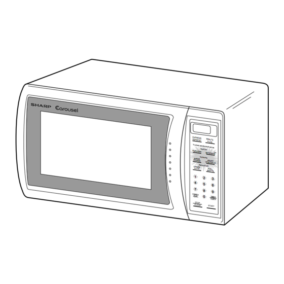
SERVICE MANUAL
MODELS
EXP RE SS
MIN UTE
DE FRO ST
PLU S
SNA CKS
POP CO
RN
BEV ERA
GE
COO KIN
BAK ED
G
POT ATO
FRE SH
VEG ETA
BLE S
REH EAT
ING
DIN NER
PLA TE
RO LL,
MU FFI N
1
2
3
4
5
6
7
8
9
0
In the interest of user-safety the oven should be restored to its original
condition and only parts identical to those specified should be used.
WARNING TO SERVICE PERSONNEL: Microwave ovens con-
tain circuitry capable of producing very high voltage and
current, contact with following parts may result in a severe,
possibly fatal, electrical shock. (High Voltage Capacitor, High
Voltage Power Transformer, Magnetron, High Voltage Recti-
fier Assembly, High Voltage Harness etc..)
TABLE OF CONTENTS
MICROWAVE OVEN
R-203BW
R-209BK
R-220BW
This document has been published to be used for after
sales service only.
The contents are subject to change without notice.
R-203BW
R-209BK
R-220BW
S1803R220BPW/
Page
Advertisement
Table of Contents


Need help?
Do you have a question about the R-203BW and is the answer not in the manual?
Questions and answers