Advertisement
Table of Contents
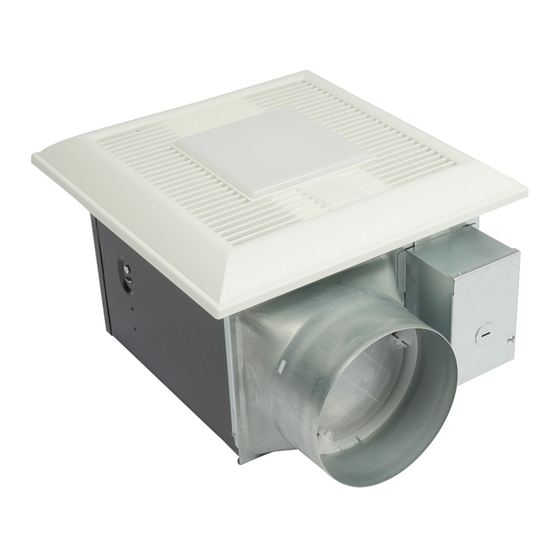
Service Manual
FV-05-11VKL1
This service information is designed for experienced repair technicians only and is not designed for use by
the general public. It does not contain warnings or cautions to advise non-technical individuals of potential
dangers in attempting to service a product. Products powered by electricity should be serviced or repaired
only by experienced professional technicians. Any attempt to service or repair the product or products dealt
with in this service information by anyone else could result in serious injury or death.
There are special components used in this equipment which are important for safety. These parts are
marked by
in the Schematic Diagrams, Exploded Views and Replacement Parts List. It is essential
that these critical parts should be replaced with manufacturer's specified parts to prevent shock, fire
or other hazards. Do not modify the original design without permission of manufacture.
We suggest to handle such parts after the static electricity prevention.
It is forbidden to touch the PCB parts by bare hands during the repairing process.
CONTENTS
1. Specifications
2. Parts Identification
3.Wiring Diagram
4. Parts List
WARNING
IMPORTANT SAFETY NOTICE
PEG1312054CE
Version:1301
Ventilating Fan
(North America Market)
FV-11-15VKL1
PAGE
1
2~9
10
11~14
Advertisement
Table of Contents

Related Manuals for Panasonic FV-05-11VKL1


Summary of Contents for Panasonic FV-05-11VKL1
- Page 1 Version:1301 Service Manual Ventilating Fan (North America Market) FV-05-11VKL1 FV-11-15VKL1 WARNING This service information is designed for experienced repair technicians only and is not designed for use by the general public. It does not contain warnings or cautions to advise non-technical individuals of potential dangers in attempting to service a product.
-
Page 2: Specifications
0.1"WG Model No. (k ) g Lighting direction (Hz) (sones) (rpm) (inches) (CFM) unit <0.3 FV-05-11VKL1 Exhaust <0.3 4 or 6 11.5(5.2) 11.0 <0.3 FV-11-15VKL1 Exhaust <0.3 12.0 11.7(5.3) 16.5 HVI Certified performance based on HVI Procedures 915,916,and 920. -
Page 3: Parts Identification
2.Parts Identification FV-05-11VKL1 Main Body Section (3pcs) (3pcs) (4pcs) (5pcs) (28) (2pcs) Main PCB Section (2pcs) (3pcs) Base PCB Section (2pcs) Ornamental Cover... - Page 4 2.Parts Identification FV-05-11VKL1 Main PCB Section (3pcs) (4pcs) Base PCB Section (2pcs) Condensation Sensor Module Sensor Cover (3pcs) Multi-Speed Control Module Nite-Glo LED Night Light Module Motion Sensor Module 1,Please note that above parts with(No.30,36,37,38) are the optional parts bas on different customer’s request.
- Page 5 2.Parts Identification FV-05-11VKL1 Packing Section (22) (2pcs)
-
Page 6: Main Label
2.Parts Identification FV-05-11VKL1 Main Label 08VSL3082 E78414 LISTED Not for use in cooking area-See installation instructions Non destiné à la zone de cuisson -Voir instructions d’installation. No usar en áreas donde cocine - Consulte las instrucciones de instalación. - Page 7 2.Parts Identification FV-11-15VKL1 Main Body Section (3pcs) (3pcs) (4pcs) (5pcs) (28) (2pcs) Main PCB Section (2pcs) (3pcs) Base PCB Section (2pcs) Ornamental Cover...
- Page 8 2.Parts Identification FV-11-15VKL1 Main PCB Section (3pcs) (4pcs) Base PCB Section (2pcs) Condensation Sensor Module Sensor Cover (3pcs) Multi-Speed Control Module Nite-Glo LED Night Light Module Motion Sensor Module 1,Please note that above parts with(No.30,36,37,38) are the optional parts bas on different customer’s request.
- Page 9 2.Parts Identification FV-11-15VKL1 Packing Section (22) (2pcs)
- Page 10 2.Parts Identification FV-11-15VKL1 Main Label 08VSL3082 E78414 LISTED Not for use in cooking area-See installation instructions Non destiné à la zone de cuisson -Voir instructions d’installation. No usar en áreas donde cocine - Consulte las instrucciones de instalación.
-
Page 11: Wiring Diagram
3.Wiring Diagram FV-05-11VKL1 FV-11-15VKL1 Fan body Junction box Switch for power (114°C Fuse) Black Live (Fan) DC-Motor (Power supply) Thermally Neutral White protected AC120V 60Hz Multi-Speed switch Hi/Low switch:When plug in Pulg ‘N Play module slot Multi-Speed module; On/Off switch:When plug in other Plug’N Play modules. -
Page 12: Parts List
4.Parts List FV-05-11VKL1 Main Body Section Part No. Part Name Q'ty Remark FFV1600138S Frame Assembly FFV0000145S Adapter Assembly FFV0900062S Connector Plate FFV1340008S Earth Lead Wire Assembly FFV0900051S Connector Assembly FFV0900067S Connector Assembly(L) FFV2800021S Junction Cover FFV0800001S Casing Support FFV3702255S Motor Assembly... - Page 13 4.Parts List FV-05-11VKL1 Base PCB Section Part No. Part Name Q'ty Remark 30 FFV5530071S Multi-Speed Module 31 FFV0900063S Connector Cover 32 FFV0410001S Base PCB Cover 33 FFV5530072S Variable Speed Switch 34 FFV0410002S Base PCB Assembly 35 FFV0410003S Base PCB Box...
- Page 14 4.Parts List FV-11-15VKL1 Main Body Section Part No. Part Name Q'ty Remark FFV1600138S Frame Assembly FFV0000146S Adapter Assembly FFV0900062S Connector Plate FFV1340008S Earth Lead Wire Assembly FFV0900051S Connector Assembly FFV0900067S Connector Assembly(L) FFV2800021S Junction Cover FFV0800001S Casing Support FFV3702255S Motor Assembly 10 FFV4620109S Motor Lead Wire Assembly 11 FFV3702257S Motor Support 12 FFV0400115S Blade...
- Page 15 4.Parts List FV-11-15VKL1 Base PCB Section Part No. Part Name Q'ty Remark 30 FFV5530071S Multi-Speed Module 31 FFV0900063S Connector Cover 32 FFV0410001S Base PCB Cover 33 FFV5530072S Variable Speed Switch 34 FFV0410002S Base PCB Assembly 35 FFV0410003S Base PCB Box 36 FFV0010237S Condensation Sensor Module 37 FFV3740029S Motion Sensor Module Include Sensor Cover...
Need help?
Do you have a question about the FV-05-11VKL1 and is the answer not in the manual?
Questions and answers