Table of Contents
Advertisement
Advertisement
Table of Contents

Related Manuals for Honda HRA214


Summary of Contents for Honda HRA214
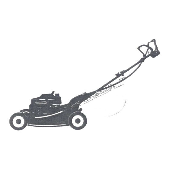
- Page 3 Any powered product can be a potential source of danger if misused or improperly maintained. Pay particular attention to statements preceded by the following words: Illustrations in this manual are based primarily on the S-XA type (self-propelled) HRA214. Indicates the possibility of personal injury or loss of life if instructions are not followed.
- Page 4 Thank you for purchasing a Honda Lawn Mower. If any problems occur, or if there are any questions concerning the niower, consult an authorized HONDA dealer. No part of this publication may be reproduced without written permission. * The Honda rotary mower is designed to give safe and dependable service if operated according to instructions and intended use: mowing (cutting) grass, and bagging cut grass when equipped with the grass bag.
-
Page 5: Table Of Contents
CONTENTS ... GENERAL SAFETY COMPONENT IDENTIFICATION CONTROLS ... OPERATION 0 High altitude operation ... TRANSPORTING/STORAGE MAINTENANCE TROUBLESHOOTING SPECIFICATIONS WARRANTY SERVICE ... CHART. -
Page 6: General Safety
GENERAL SAFETY * Know how to stop the engine quickly and under- stand operation of all the controls. Never permit anyone to operate the mower without struction. * The rear shield is for your protection; in place at all times. * The blade is sharp and dangerous. -
Page 7: Component Identification
COMPONENT IDENTIFICATION ROTO-STOP LEVER RECOIL STARTER THROlTLE LEVER SPARK PLUG CAP MUFFLER GRASS BAG HANDLE AIR CLEANER... - Page 8 DRIVE CLUTCH LEVER HANDLE FUEL TANK CAP DISCHARGE GUARD OIL FILLER ENGINE OIL DRAIN PLUG...
-
Page 9: Controls
CONTROLS Throttle (All types) “CHOKE” “HI” “LO” “STOP” ROTOGTOP Lever (All types) To put the cutting blade into operation, press the button on top of the ROTO-STOP lever and push the lever forward, holding it against the handlebar. The blade will stop when the ROTO-STOP lever is released. - Page 10 Drive Clutch Lever (Self-propelled type) propel the mower, push the drive clutch lever forward and hold it against the handlebar. Release the lever to disengage the drive. To propel the mower and operate the cutting blade simultaneously, push the button ROTO-STOP lever, then push the drive clutch forward;...
-
Page 11: Operation
This MOWER should be used with the grass bag. The following suggestions and rules are intended to help you operate your Honda HRA214 under the safest conditions possible. Be alert and exercise the same care using’the mower as you would using any other power tool. -
Page 12: Before Start The Mower
BEFORE YOU START THE MOWER 1. Check the engine oil level. f-emmq * Engine oil is a major factor affecting engine per- formance and service life. Non-detergent or veget- able oils are not recommended. * Running the engine with insufficient serious engine damage. - Page 13 2. Check the fuel level. Your engine is designed to use any gasoline that has a pump octane number ( 9 ) of 86 or higher, or that has a research octane number of 91 or higher. Gasoline pumps at service station normally display the pump octane number.
- Page 14 Gasolines Containing Alcohol If you decide to use a gasoline containing (gasohol), be sure it’s octane rating is at least as high as that recommended by Honda. There are two types of “gasohol”: one containing ethanol, and the other containing methanol.
-
Page 15: High Altitude Operation
3. Check the grass bag for fraying, tears and clogged mesh. Wash the bag with water if necessary, and let it dry thoroughly. Grass will not chute proper- ly without adequate ventilation Make sure the lock lever is latched securely. 4. -
Page 16: Starting The Engine
STARTING THE ENGINE Exhaust gas contains poisonous carbon monoxide. Never run the mower in an enclosed area. Be sure to provide adequate ventilation. 1. Move the throttle lever to “CHOKE”. NOTE: Do not use “CHOKE” when the engine is warm or the air temperature is high. - Page 17 3. Place your foot on the “STEP” housing 4. Pull the starter rope lightly until you feel compres- sion, then pull briskly. NOTE: Do not allow the rope to snap back; return it by hand. 5. After the engine warms up, move the throttle lever to “HI”.
- Page 18 Flooded Engine If the engine won’t start after several pulls on the starter rope the engine is probably flooded. To clear a flooded engine: 1. Move the throttle lever to “STOP” and turn off the fuel valve. 2. Remove and dry the spark plug. When re-installing the plug, thread it in by hand until it seats.
- Page 19 Cutting Height Adjustment Five settings are available: 1”. l-1/2”, 1. Stop the engine. 2. Push the front and rear adjusting levers toward the wheels and move them up or down to raise or lower cutting height. Adjust front and rear wheels to the same height.
- Page 20 Grass Bag The bag is subject to wear under normal usage; frequently check for fraying and tears. Replace deteriorated bags only with Honda replacement bags or equivalent. When the bag needs cleaning, wash it with water and make sure it is dry before using it. Clogged mesh will result in poor grass chutting and a wet bag will clog quickly.
-
Page 21: Transporting/Storage
TRANSPORTING/STORAGE Transporting Turn the fuel valve OFF when transporting mower. * To avoid fuel and oil spillage do not tilt the unit; spilled fuel may ignite. Preparation for Storage The following steps should be taken to protect the mower whenever it will be stored for longer than ‘30 days. - Page 22 B. Loosen the carburetor drain bolt to drain the carburetor. C. Retighten the drain bolt, connect the fuel tube and turn the fuel valve OFF. * Gasoline is extremely flammable under certain conditions. Do not smoke or allow flames or sparks in the area 2.
- Page 23 3. Pull the starter rope until resistance is felt. This closes the valves and helps to protect the com- bustion chamber from corrosion. 4. Coat areas that may rust with a light film of oil. Cover the mower and store it on a level surface in a dry, dust free area.
-
Page 24: Maintenance
Periodic inspection and adjustment HRA214 are essential if high level performance is to be maintained. Regular maintenance will also help to extend service life. The required service intervals and the kind of maintenance to be performed are des- cribed in the chart on the following page. -
Page 25: Maintenance Schedule
MAINTENANCE SCHEDULE (1) Service more frequently when used in dusty areas. (2) These items should be serviced by an authorized Honda dealer, unless the owner has the proper tools and is mechanically proficient. See the Honda Shop Manual. (3) For professtonal commercial use, log hours of operation to detemine proper maintenance intervals. -
Page 26: Engine Oil Change
ENGINE OIL CHANGE Dram the oil while the engine is still warm to assure rapid and complete draining. 1. Remove the filler cap. 2. Remove the drain bolt, drain the oil, and retighten the bolt securely. 3. Refill to the “Upper” level mark with the recom- meded oil (see p. -
Page 27: Air Cleaner Service
AIR CLEANER SERVICE A dirty air cleaner will restrict air flow to .the carbu- retor. To prevent carburetor malfunction, air cleaner frequently. 1. Remove the wing bolts and the air cleaner cover. Remove the elements and separate them. Carefully check both elements for holes or tears and replace if damaged. -
Page 28: Spark Plug
SPARK PLUG Standard BPSES, BPRSES (NGK) Plug: W 16EP-U, W 16EPR-U (ND) 1. Disconnect the cap and remove the spark plug. 2. Visually inspect the plug. Discard the plug if it is heavily deposited or if the insulator is cracked or chipped. -
Page 29: Blade Removal/Sharpening
BLADE REMOVAL AND SHARPENING * Wear heavy gloves to protect your hands. * Disconnect the spark plug cap to prevent acciden- tal start-up. 1. Turn the fuel valve to “OFF,” carburetor (see p. 19). 2. Tilt the mower so the carburetor side is up. Remove the blade bolts to remove the blade. -
Page 30: Throttle Control Cable Adjustment
THROTTLE CONTROL CABLE ADJUSTMENT 1. With the throttle lever in the “CHOKE” the carburetor choke arm should move all the way to the right, as far as it will go. Push the choke arm with your finger to check whether it is all the way to the right. - Page 31 ROTO-STOP LEVER FREE PLAY (All TYPES) Measure free play at the tip of the lever with the button pushed down, it should be between 5 - 10 mm (3/ 16 - 3/8 in). 2. If adjustment is necessary, loosen the lock nuts and turn them to run the adjuster up or down as required.
- Page 32 DRIVE CLUTCH FREE PLAY (Self-propelled type only) 1. Measure free play at the top of the lever as shown; it should be between S-10 mm (3/16-3/8 in). 2. If adjustment is necdssary, loosen the lock nuts and turn them to run the adjuster up or down as required.
-
Page 33: Spark Arrester Maintenance
SPARK ARRESTER MAINTENANCE (Optional part) If the mower has been running. the muffler will be very hot. Allow it to cool before proceeding. 1. Loosen two 6 mm nuts and remove the muffler protector, identification plate, muffler camp and gasket. 2. - Page 34 NOTE: following adjustments should an authorized Honda dealer unless the owner has the tools and is mechanically proficient. proper 1. Start the engine and allow it to warm up to normal operating temperature. 2. Place the throttle lever in the “LO” position. 3.
-
Page 35: Grass Bag Assembly
GRASS BAG ASSEMBLY 1. Insert the. bag frame into the grass bag as shown. 2. Hook the plastic edges of the grass bag onto the frame. -
Page 36: Troubleshooting Chart
TROUBLESHOOTING CHART Engine will not start Hard starting or loss of power Erratic operation Engine overheats Excessive vibration 1. No fuel. 2. Throttle lever in “STOP” position. 3. Spark plug wire loose or disconnected. 4. Spark plug faulty or improperly gapped (p. 26). 5. -
Page 37: Specifications
Dry weight Grass bag capacity Cutting width NOTE: Specifications are subject to change without notice. HRA214 GXVl20 Over head valve, single-cylinder, forced air-cooled four-stroke gasoline engine. 118 cm3 (7.2 cu in)/60 X 42 mm (2.4 X 1.7 in) 25” - 27” BTDC Transistor magneto ignition 0.6 P (0.63 US qt, 0.53 Imp qt) -
Page 38: Warranty Service
WARRANTY SERVICE Owner Satisfaction Your satisfaction and goodwill explained in the Distributor’s Limited Warranty.Normally, be handled by your dealer’s service dapartment. handled to your satisfaction, we suggest Discuss your problem with a member of dealership resolved at that level. If the problem has already been reviewed the owner of the dealership If your problem still has not been resolved to your satisfaction,... - Page 39 When you write or call, please provide the following information: • Model and serial numbers • Name of the dealer who sold the Honda power equipment to you • Name and address of the dealer who services your equipment •...
Need help?
Do you have a question about the HRA214 and is the answer not in the manual?
Questions and answers
je cherche le numero roue de tondeuse modele hra214 honda
The wheel part number for the Honda HRA214 lawn mower is 42710-VA3-J00.
This answer is automatically generated