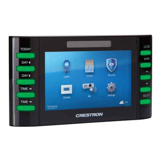
Summary of Contents for Crestron TPCS-4SM
- Page 1 Crestron TPCS-4SM & TPCS-4SMD 4.3” Touch Screen Control Systems Configuration Guide...
- Page 2 United States and/or other countries. Other trademarks and trade names may be used in this document to refer to either the entities claiming the marks and names or their products. Crestron disclaims any proprietary interest in the marks and names of others.
-
Page 3: Table Of Contents
Crestron TPCS-4SM & TPCS-4SMD Touch Screen Control Systems Contents 4.3” Touch Screen Control Systems: TPCS-4SM & TPCS-4SMD Access the Setup Screens......................1 Configure the TPCS-4SM or TPCS-4SMD ................3 Ethernet Setup ......................3 Audio Setup......................... 8 Display Setup ......................8 Application Setup ...................... -
Page 5: Touch Screen Control Systems: Tpcs-4Sm & Tpcs-4Smd
Control Systems: TPCS-4SM & TPCS-4SMD Access the Setup Screens The setup screens are the starting point for configuring the TPCS-4SM and ® TPCS-4SMD from Crestron NOTE: If no project has been loaded or if an invalid project has been loaded, the TPCS-4SM and TPCS-4SMD default to the setup screens. - Page 6 NOTE: For hard key numbering refer to the “Diagnostic – Keypad” illustration at the bottom of page 12. The “TPCS-4SM Setup” (or “TPCS-4SMD Setup”) menu is comprised of buttons for Ethernet Setup, Audio Setup, Display Setup, Application Setup, Standby Timeout and Diagnostics. In addition, there are buttons that provide information about the touch screen and a Save &...
-
Page 7: Configure The Tpcs-4Sm Or Tpcs-4Smd
Touch Screen Control Systems Configure the TPCS-4SM or TPCS-4SMD Ethernet Setup On the “TPCS-4SM[D] Setup” menu, touch Ethernet Setup to display the “Ethernet Setup” menu, shown in the following illustration. “Ethernet Setup” Menu The “Ethernet Setup” menu displays current settings, such as whether DHCP is on or off, the touch screen’s Hostname and its IP Address. - Page 8 Setup” menu to reboot the touch screen, so the new settings can take effect. Touch Advanced Settings to display the “Advanced Ethernet Setup” menu, shown in the following illustration. 4 • 4.3” Touch Screen Control Systems: TPCS-4SM & TPCS-4SMD Configuration Guide – DOC. 7332A...
- Page 9 CA: Uses an authority to assign the SSL certificates NOTE: For more details on SSL settings, refer to the latest version of the 3-Series Control Systems Reference Guide (Doc. 7150). It is available from the Crestron Web site at www.crestron.com/manuals.
- Page 10 “Ethernet Setup” menu. On the “Ethernet Setup” menu, touch Ethernet Diagnostics to display the “Ethernet Diagnostics” screen, shown in the following illustration. “Ethernet Diagnostics” Screen 6 • 4.3” Touch Screen Control Systems: TPCS-4SM & TPCS-4SMD Configuration Guide – DOC. 7332A...
- Page 11 Touch Who to display a list of devices connected to the PC via the Ethernet connection. These devices may be Crestron Ethernet devices, third-party Ethernet devices or PCs (including any PC using Crestron Toolbox™ to connect to the processor via Ethernet).
-
Page 12: Audio Setup
Touch Screen Control Systems Crestron TPCS-4SM & TPCS-4SMD Audio Setup On the “TPCS-4SM[D] Setup” menu, touch Audio Setup to display the “Audio Setup” screen, shown in the following illustration. “Audio Setup” Screen The “Audio Setup” screen provides controls for muting (or unmuting) the audio, adjusting Volume and playing a test .wav file. - Page 13 On and Off controls for Hard Key Wakes LCD and Proximity Sensor Wakes LCD. TPCS-4SMD “Display Setup” Screen Touch to return to the “TPCS-4SM[D] Setup” menu. 4.3” Touch Screen Control Systems: TPCS-4SM & TPCS-4SMD • 9 Configuration Guide – DOC. 7332A...
-
Page 14: Application Setup
Touch Screen Control Systems Crestron TPCS-4SM & TPCS-4SMD Application Setup On the “TPCS-4SM[D] Setup” menu, touch Application Setup to display the “Application Setup” screen, shown in the following illustration. “Application Setup” Screen The “Application Setup” screen has controls to enable or disable the user program from running when the device boots and to restart the program. -
Page 15: Standby Timeout
Touch again to return to the “TPCS-4SM[D] Setup” menu. Standby Timeout On the “TPCS-4SM[D] Setup” menu, touch Standby Timeout to display the “Standby Timeout” screen, shown in the following illustration. “Standby Timeout” Screen The “Standby Timeout” screen provides controls to adjust standby timeout from 0 to 120 minutes. -
Page 16: Diagnostics
Touch Screen Control Systems Crestron TPCS-4SM & TPCS-4SMD Diagnostics On the “TPCS-4SM[D] Setup” menu, touch Diagnostics to display the “Diagnostics” menu, shown in the following illustration. “Diagnostics” Menu The “Diagnostics” menu displays the Available Memory and contains controls to Show Hardware Configurations, Show Cresnet Devices, Show Message Log, Show Last Reboot Message and Performance Statistics. - Page 17 On the “Diagnostics” menu, touch Proximity Sensor Test to display the “Diagnostic – Sensor Test” screen, shown in the illustration below. “Diagnostic – Sensor Test” Screen 4.3” Touch Screen Control Systems: TPCS-4SM & TPCS-4SMD • 13 Configuration Guide – DOC. 7332A...
- Page 18 On the “Diagnostics” menu, touch Calibrate to initiate the screen calibration procedure. Refer to “Touch Test” on page 13 for details. Touch to return to the “TPCS-4SM[D] Setup” menu. 14 • 4.3” Touch Screen Control Systems: TPCS-4SM & TPCS-4SMD Configuration Guide – DOC. 7332A...
-
Page 19: About
“TPCS-4SM[D] Setup” menu. Save & Exit On the “TPCS-4SM[D] Setup” menu, touch Save & Exit to save all settings, exit the setup screens and return to the main project. 4.3” Touch Screen Control Systems: TPCS-4SM & TPCS-4SMD • 15... - Page 20 Crestron Electronics, Inc. Configuration Guide – DOC. 7332A 15 Volvo Drive Rockleigh, NJ 07647 (2032882) Tel: 888.CRESTRON 08.12 Fax: 201.767.7576 Specifications subject to www.crestron.com change without notice.


Need help?
Do you have a question about the TPCS-4SM and is the answer not in the manual?
Questions and answers