Table of Contents
Advertisement
Quick Links
Advertisement
Table of Contents

Related Manuals for Crestron Zum


Summary of Contents for Crestron Zum
- Page 1 Crestron Zūm® Wired Solutions Product Manual Crestron Electronics, Inc.
- Page 2 All other languages are a translation of the original instructions. Regulatory Model: M201903003 This product may be purchased from select authorized Crestron dealers and distributors. To find a dealer or distributor, please contact the Crestron sales representative for your area. A list of sales representatives is available online at www.crestron.com/How-To-Buy/Find-a-Representative...
-
Page 3: Table Of Contents
Contents Overview Load Controllers Keypad Presence Detectors Software Zūm App Custom Program License for the ZUM-HUB4 Accessories Cables Adapter Cable RJ-45 Splitter Zūm Link Power Supply Rocker Button and Button Trees Features Load Controller Features Keypad Features Presence Detector Features... - Page 4 Keypad Specifications Product Specifications Dimension Drawings Presence Detector Specifications Product Specifications Dimension Drawings Hub Specifications ZUM-HUB4 Specifications ZUM-HUB4 Dimension Drawings ZUML-HUB4-GW Specifications ZUML-HUB4-GW Dimension Drawings ZUML-HUB4-PAK Specifications ZUML-HUB4-PAK Dimension Drawings ZUML-HUB4-CN-PAK Specifications ZUML-HUB4-CN-PAK Dimension Drawings Zūm App Specifications Cable Specifications...
- Page 5 In the Box Install the Keypad Wire the Keypad Mount the Keypad Replace the Rocker Button/Button Tree and Bezel Presence Detectors Installation In the Box Remove or Attach the Backplate Junction Box Mounting Ceiling Mounting Hub Installation In the Box Mount to a Rack Place onto a Flat Surface Make Connections...
- Page 6 Presence Detector App Configuration Hub Web Interface Web Interface Overview Web Interface Configuration Resources Crestron Support and Training Programmer and Developer Resources Product Certificates Related Documentation Models Load Controllers Keypad Presence Detectors Hub and Kits Software Power Supply Cables Cable Accessories Rocker and Button Trees...
- Page 7 vii • Contents Product Manual — Doc. 9349B...
-
Page 8: Overview
DALI®, DMX and phase control all merged on an enterprise IoT network, Zūm Net. This network not only provides communication and control of your lighting, but also seamlessly integrates with Crestron® Unified Communications systems and third- party occupancy, environmental & acoustical sensors or other data related IoT devices. - Page 9 ZUMLINK-EXP-16A-DIMU provides superior immunity to power line noise, resulting in a significant reduction of lamp flicker. Energy-saving options (sold separately) are available to enable daylighting, occupancy or vacancy sensing, integration, and centralized monitoring and management. 9 • Crestron Zūm® Wired Solutions Product Manual — Doc. 9349B...
-
Page 10: Keypad
(not included). The RLY presence detectors also have a three-wire output relay to connect to a relay-input capable device, such as an HVAC call system. Product Manual — Doc. 9349B Crestron Zūm® Wired Solutions • 10... - Page 11 ZUMLINK-US-ONEWAY-DLS-RLY with ultrasonic technology and unidirectional detection for hallways All Zūm Link Wired Presence Detectors are functionally similar. For simplicity within this guide, the term "presence detectors" is used except where otherwise noted. 11 • Crestron Zūm® Wired Solutions Product Manual — Doc. 9349B...
-
Page 12: Hub
The ZUM-HUB4 enables centralized management for Zūm® commercial lighting systems of up to 1,000 rooms with an Ethernet switch (sold separately) across Zūm wired, Zūm wireless, and external spaces. The device provides a web-based user interface for control. A built-in time clock enables room lighting and occupancy and vacancy sensing automation. -
Page 13: Software
The SW-HUB4-PROG is a software license that activates the custom program slot on the ZUM-HUB4 control system. The custom program slot allows a ZUM-HUB4 control system to run a custom program in parallel with the centralized management native to the ZUM-HUB4. Create and update programs that provide custom functionality without affecting the centralized management of the ZUM-HUB4. -
Page 14: Accessories
For support, contact license@crestron.com. Accessories Zūm Wired accessories include cables, power supply, custom programming for the ZUM-HUB4, and button trees for keypads. Cables Zūm Wired cables terminate with RJ-45 connectors for easy wiring. The cables area available in various lengths for both Zūm Link and Zūm Net applications. -
Page 15: Adapter Cable
Zūm Link ports. It is plenum rated and works with Zūm Link devices. For flexible, in-room wiring, use with the ZUMLINK-CONV-CN to daisy chain Zūm Link devices with Cresnet® devices. 15 • Crestron Zūm® Wired Solutions Product Manual — Doc. 9349B... -
Page 16: Zūm Link Power Supply
The ZUMLINK-KP comes installed with a white ZUMLINK-BTNR ENGRAVED rocker button, but may be replaced with any of the other ZUMLINK-BTN button trees. Product Manual — Doc. 9349B Crestron Zūm® Wired Solutions • 16... -
Page 17: Features
Keypad Features • Presence Detector Features • Hub Features • Software Features • Cable Features • Cable Accessory Features • Power Supply Features • Rocker and Button Tree Features Product Manual — Doc. 9349B Crestron Zūm® Wired Solutions • 17... -
Page 18: Load Controller Features
Zūm® wired junction box mounted lighting load dimmer Dimming control of 0-10V LED drivers or 4-wire fluorescent ballasts Integration with Zūm keypads, presence detectors, and daylight sensors (sold separately) Ethernet network connection to ZUM-HUB4 a control system (sold separately) ZūmNet Wired Technology In a Zūm network, Zūm Net load controllers facilitate communications between rooms via... - Page 19 (FP-G Series, sold separately). Override Contact Closure Input An integrated contact closure provides the means to place all connected Zūm Net and Zūm Link devices into Emergency Override mode. Product Manual — Doc. 9349B Crestron Zūm® Wired Solutions • 19...
- Page 20 Zūm® wired junction box mounted DALI® drivers lighting controller Control of DALI compliant dimmable LED or fluorescent loads Integration with Zūm keypads, presence detectors, and daylight sensors (sold separately) Ethernet network connection to ZUM-HUB4 a control system (sold separately) Zūm Net Wired Technology In a Zūm network, Zūm Net load controllers facilitate communications between rooms via...
- Page 21 14) to RJ-45 ports provide simple daisy-chaining and lighting control of compatible loads. The Zūm Wired devices work together in a local ecosystem to provide customized solutions using the Zūm app. Product Manual — Doc. 9349B Crestron Zūm® Wired Solutions • 21...
- Page 22 Zūm® wired junction box mounted lighting load plug load controller Integration with Zūm keypads, presence detectors, and daylight sensors (sold separately) Zero-cross switching with the ability to switch control of 20A plug loads Supports in-room device daisy chaining 22 • Crestron Zūm® Wired Solutions Product Manual — Doc. 9349B...
- Page 23 (FP-G Series, sold separately). Override Contact Closure Input An integrated contact closure provides the means to place all connected Zūm Net and Zūm Link devices into Emergency Override mode. Product Manual — Doc. 9349B Crestron Zūm® Wired Solutions • 23...
- Page 24 8) and connect them with Zūm Link (CBL-CAT5E-ZUMLINK-P) or Zūm Net (CBL-CAT5E-ZUMNET-P) CAT5e cable (refer to Cables on page 14). Nonsystem presence detectors may also be installed to any load controller with analog inputs. 24 • Crestron Zūm® Wired Solutions Product Manual — Doc. 9349B...
- Page 25 14) to RJ-45 ports provide simple daisy-chaining and lighting control of compatible loads. The Zūm Wired devices work together in a local ecosystem to provide customized solutions using the Zūm app. Product Manual — Doc. 9349B Crestron Zūm® Wired Solutions • 25...
- Page 26 Plenum Rated NEMA Enclosure The Crestron Zūm® Wired Solutions is designed to be mounted to a vertical surface and meets the requirements of UL® 2043 for installation in an environmental air-handling space (plenum) above a suspended ceiling.
-
Page 27: Keypad Features
The keypad is equipped with a single, white rocker button for switching or dimming control and is configurable with four, six, or eight pad printed or engravable button trees (sold separately). Product Manual — Doc. 9349B Crestron Zūm® Wired Solutions • 27... - Page 28 Room setup can be accomplished quickly through the Zūm app. A finished installation requires a decorator-style faceplate (FP-G Series, sold separately). 28 • Crestron Zūm® Wired Solutions Product Manual — Doc. 9349B...
-
Page 29: Presence Detector Features
8) and connect them with Zūm Link (CBL-CAT5E-ZUMLINK-P) or Zūm Net (CBL-CAT5E-ZUMNET-P) CAT5e cable (refer to Cables on page 14). Nonsystem presence detectors may also be installed to any load controller with analog inputs. Product Manual — Doc. 9349B Crestron Zūm® Wired Solutions • 29... - Page 30 Save a room configuration template and share it via the ZUM-HUB4 or the Zūm app. The ZUMLINK-KP Bluetooth® connection is required to configure a Zūm wired space with the Zūm app.
-
Page 31: Hub Features
Net device (ZUMNET-JBOX-DALI, ZUMNET-JBOX-16A-LV, sold separately), and daisy-chain up to 20 Zūm Net devices with CBL-CAT5E-ZUMNET-P cable. For centralized management of a Zūm Wired System, connect the chain directly to a ZUM-HUB4 or multiple chains to an Ethernet switch (sold separately) to support up to 1,000 rooms. - Page 32 Mirrored Rooms: An external Crestron system controls and monitors a room equipped with a Zūm system. Mirrored rooms allow for room control with a Crestron touch screen or handheld remote, as well as integration with shading, climate control, AV, and other equipment.
- Page 33 For additional details and specifications, refer to the ZUM-HUB4 information in this guide and the PW-2420RU, ZUMNET-GATEWAY, and PW-2407WU product pages. ZUML-HUB4-PAK Facilitates quick setup of a centrally managed Zūm light control system Convenient preassembled lighting control cabinet Contains a ZUM-HUB4 Zūm hub, PW-2420RU power pack, CEN-SW-POE-5 switch, and...
- Page 34 1. SIMPL+® software modules are provided for use in commissioning a Crestron control system to work with the ZUM-HUB4. The software modules run within the control system program and provide virtual connections for all the necessary intersystem control signals. A separate dedicated module is required for each external and mirrored room.
-
Page 35: Software Features
Software Features Refer to the following sections for Zūm app and ZUM-HUB4 custom program license software features. Zūm App Features for the Zūm app are provided below. Mobile configuration tool for Zūm® wired and wireless commercial lighting systems Compatible with iOS® and Android™ operating systems Bluetooth®... -
Page 36: Cable Features
Plenum-rated jacket RJ-45 connectors with dust cap Available in four lengths CBL-CAT5E-ZUMNET-P cables connect a Zūm Net device to a ZUM-HUB4 control system (refer Hub on page 12), an Ethernet switch, or to other Zūm Net devices. This enables LAN communications and device daisy-chaining between rooms within a Zūm Wired system. -
Page 37: Cable Accessory Features
Zūm Link ports. It is plenum rated and works with Zūm Link devices. For flexible, in-room wiring, use with the ZUMLINK-CONV-CN to daisy chain Zūm Link devices with Cresnet® devices. Product Manual — Doc. 9349B Crestron Zūm® Wired Solutions • 37... -
Page 38: Power Supply Features
8) and connect them with Zūm Link (CBL-CAT5E-ZUMLINK-P) or Zūm Net (CBL-CAT5E-ZUMNET-P) CAT5e cable (refer to Cables on page 14). Nonsystem presence detectors may also be installed to any load controller with analog inputs. 38 • Crestron Zūm® Wired Solutions Product Manual — Doc. 9349B... -
Page 39: Rocker And Button Tree Features
ZUMLINK-BTN8: ON, OFF, ON, OFF, ˄, ˅, ˄, ˅ Custom Engraving Crestron Engraver software makes it easy to specify and order button trees with custom engravings for a ZUMLINK-KP Zūm Wired Keypad. Visit the following product pages to view the various button configurations and colors offered for the custom engraved models. - Page 40 In addition to custom engraving and pad printed buttons, blank buttons are available. Visit the following product pages to view the various button configurations and colors offered. ZUMLINK-BTN2 BLANK ZUMLINK-BTNR BLANK ZUMLINK-BTN4 BLANK ZUMLINK-BTN6 BLANK ZUMLINK-BTN8 BLANK 40 • Crestron Zūm® Wired Solutions Product Manual — Doc. 9349B...
-
Page 41: Application Scenarios
Daisy-chain up to 20 Zūm Net devices (up to 328 ft (100 m) between Zūm Net devices) with purple CBL-CAT5E-ZUMNET-P RJ-45 cables (sold separately). Do not exceed three network switches between a ZUM-HUB4 and a Zūm Net device. System sensors communicate digitally via Zūm Link. Non-system sensors communicate via an analog connection on a Zūm Wired load controller. - Page 42 Integrating a Legacy Lighting System into a Zūm System Using a Zūm Link Splitter (ZUMLINK-SPLTR-RJ45) 42 • Crestron Zūm® Wired Solutions Product Manual — Doc. 9349B...
-
Page 43: Specifications
Keypad Specifications • Presence Detector Specifications • Hub Specifications • Zūm App Specifications • Cable Specifications • Cable Accessory Specifications • Power Supply Specifications • Rocker and Button Tree Specifications Product Manual — Doc. 9349B Crestron Zūm® Wired Solutions • 43... -
Page 44: Load Controller Specifications
24V, OCC, GND Occupancy sensor input; 85mA available output current; Spring clamp connector 24V, PHO, GND Photo sensor input; Spring clamp connector OVR, GND Override control input; Spring clamp connector 44 • Crestron Zūm® Wired Solutions Product Manual — Doc. 9349B... - Page 45 Mounts to the side of a 4 in. square junction box via a 1/2 in. conduit knockout; Meets the requirements of UL 2043 for installation in an environmental air- handling (plenum) space Dimensions Height 4.83 in. (123 mm) Width 4.25 in. (108 mm) Depth 2.03 in. (52 mm) Product Manual — Doc. 9349B Crestron Zūm® Wired Solutions • 45...
-
Page 46: Zumnet-Jbox-16A-Lv Dimension Drawings
ZUMNET-JBOX-16A-LV Dimension Drawings ZUMNET-JBOX-DALI Specifications Load Control Load Types Control of DALI compliant dimmable LED or fluorescent loads DALI Groups Drivers Power Requirements Line Voltage 100-277VAC, 50/60 Hz Wired Communications 46 • Crestron Zūm® Wired Solutions Product Manual — Doc. 9349B... - Page 47 24V, OCC, GND Occupancy sensor input; 85mA available output current; Spring clamp connector 24V, PHO, GND Photo sensor input; Spring clamp connector OVR, GND Override control input; Spring clamp connector Product Manual — Doc. 9349B Crestron Zūm® Wired Solutions • 47...
- Page 48 Mounts to the side of a 4 in. square junction box via a 1/2 in. conduit knockout; Meets the requirements of UL 2043 for installation in an environmental air- handling (plenum) space Dimensions Height 4.83 in. (123 mm) Width 4.25 in. (108 mm) Depth 2.03 in. (52 mm) 48 • Crestron Zūm® Wired Solutions Product Manual — Doc. 9349B...
-
Page 49: Zumnet-Jbox-Dali Dimension Drawings
Load Rating 16A 100-277VAC, 50/60 Hz; 0.5 HP @ 120-277VAC Dim Control Output 0-10VDC, 60mA maximum sink or source Short Circuit Protection 40A non-replaceable fuse Product Manual — Doc. 9349B Crestron Zūm® Wired Solutions • 49... - Page 50 24V, OCC, GND Occupancy sensor input; 85mA available output current; Spring clamp connector 24V, PHO, GND Photo sensor input; Spring clamp connector OVR, GND Override control input; Spring clamp connector 50 • Crestron Zūm® Wired Solutions Product Manual — Doc. 9349B...
- Page 51 Mounts to the side of a 4 in. square junction box via a 1/2 in. conduit knockout; Meets the requirements of UL 2043 for installation in an environmental air- handling (plenum) space Dimensions Height 4.83 in. (123 mm) Width 4.25 in. (108 mm) Depth 2.03 in. (52 mm) Weight 7 oz (199 g) Product Manual — Doc. 9349B Crestron Zūm® Wired Solutions • 51...
-
Page 52: Zumlink-Jbox-16A-Lv Dimension Drawings
Load Rating 20A 100-277VAC, 50/60 Hz high inrush, zero-cross switching; 0.5 HP @ 120-277VAC Short Circuit Protection 40A non-replaceable fuse Power Requirements Line Voltage 100-277VAC, 50/60 Hz 52 • Crestron Zūm® Wired Solutions Product Manual — Doc. 9349B... - Page 53 24V, OCC, GND Occupancy sensor input; 85mA available output current; Spring clamp connector 24V, PHO, GND Photo sensor input; Spring clamp connector OVR, GND Override control input; Spring clamp connector Product Manual — Doc. 9349B Crestron Zūm® Wired Solutions • 53...
- Page 54 7 oz (199 g) Compliance Regulatory Model: M201933002 cUL916, cUL2043 UL® Listed for US & Canada, IC, FCC Part 15 Class A digital device, UL 916, UL 2043, UL 94 5VA 54 • Crestron Zūm® Wired Solutions Product Manual — Doc. 9349B...
-
Page 55: Zumlink-Jbox-20A-Plug Dimension Drawings
Power Requirements Line Voltage 100-277VAC, 50/60 Hz Wired Communications ZUMLINK (ROOM) (2) RJ-45 ports; In-room Zūm Link device daisy-chaining; 85mA power available for Zūm Link devices, including ZUMLINK-KP keypads Product Manual — Doc. 9349B Crestron Zūm® Wired Solutions • 55... - Page 56 24V, OCC, GND Occupancy sensor input; 85mA available output current; Spring clamp connector 24V, PHO, GND Photo sensor input; Spring clamp connector OVR, GND Override control input; Spring clamp connector 56 • Crestron Zūm® Wired Solutions Product Manual — Doc. 9349B...
- Page 57 Mounts to the side of a 4 in. square junction box via a 1/2 in. conduit knockout; Meets the requirements of UL 2043 for installation in an environmental air- handling (plenum) space Dimensions Height 4.83 in. (123 mm) Width 4.25 in. (108 mm) Depth 2.03 in. (52 mm) Weight 7 oz (199 g) Product Manual — Doc. 9349B Crestron Zūm® Wired Solutions • 57...
-
Page 58: Zumlink-Jbox-20A-Sw Dimension Drawings
Dimmer Channels Load Rating Line/Load Voltage: 100-277VAC, 50/60 Hz Dimmable Load Types: Incandescent, LED, electronic low-voltage, magnetic low-voltage, neon/cold cathode, 2-wire fluorescent Communications Zūm Link in-room control Controls and Indicators 58 • Crestron Zūm® Wired Solutions Product Manual — Doc. 9349B... - Page 59 Dimmed load output; 24 to 10 AWG (0.25 to 4.0 mm2) wire size Ground (1) 3-terminal grounding block Environmental Temperature 32° to 104°F (0° to 40°C) Humidity 10% to 90% RH (noncondensing) Construction Product Manual — Doc. 9349B Crestron Zūm® Wired Solutions • 59...
- Page 60 Dimensions Height 8.80 in. (223 mm) Width 6.40 in. (162 mm) Depth 3.17 in. (80 mm) Weight 3.43 lb (1.56 kg) Compliance Regulatory Model: M201933001 IC, FCC Part 15 Class A digital device, UL508 60 • Crestron Zūm® Wired Solutions Product Manual — Doc. 9349B...
-
Page 61: Zumlink-Exp-16A-Dimu Dimension Drawings
ZUMLINK-EXP-16A-DIMU Dimension Drawings Product Manual — Doc. 9349B Crestron Zūm® Wired Solutions • 61... -
Page 62: Keypad Specifications
Mounts in a 1-gang, 3.5 in. (89 mm) deep electrical box (not supplied) Faceplate Requires a decorator style faceplate (FP-G Series, not supplied) Dimensions Height 4.13 in. (105 mm) Width 1.50 in. (38 mm) Depth 1.28 in. (33 mm) Weight 5 oz (142 g) 62 • Crestron Zūm® Wired Solutions Product Manual — Doc. 9349B... -
Page 63: Dimension Drawings
Regulatory Model: M201937001 UL® Listed for US & Canada, IC, FCC Part 15 Class B digital device, UL 916, CSA C22.2 No. 205, CEC Title 24, ASHRAE 90.1, IECC Dimension Drawings Product Manual — Doc. 9349B Crestron Zūm® Wired Solutions • 63... -
Page 64: Presence Detector Specifications
7.9 x 7.9 m (62 sq m) Tangential: Motion perpendicular to the sensor; Maximum: 65.5 x 65.5 ft (4290 sq ft)/ 20 x 20 m (400 sq m) Light Level Setting 10-1000lux / 1-100 fc 64 • Crestron Zūm® Wired Solutions Product Manual — Doc. 9349B... - Page 65 Minimum: 6.5 x 20 ft (130 sq ft)/ 2 x 5 m (10 sq m) Light Level Setting 10-1000lux / 1-100 fc Dimensions Height: 4.73 in. (121 mm) Width: 4.73 in. (121 mm) Depth: 2.84 in. (72 mm) Product Manual — Doc. 9349B Crestron Zūm® Wired Solutions • 65...
- Page 66 Width: 4.73 in. (121 mm) Depth: 2.67 in. (68 mm) Controls & Indicators (3) Blue LEDs on the sensor head frontplate Flashes upon start up and when triggered to identify itself 66 • Crestron Zūm® Wired Solutions Product Manual — Doc. 9349B...
- Page 67 Mount directly in the ceiling, 4 in. square or round junction boxes (not included), or 3 in. mud rings (not included) Compliance Regulatory Mode: M202111001, M202111002, M202111003, and M202111004 UL® Listed Product Manual — Doc. 9349B Crestron Zūm® Wired Solutions • 67...
-
Page 68: Dimension Drawings
Dimension Drawings ZUMLINK-IR-QUATTRO-DLS and ZUMLINK-IR-QUATTRO-DLS-RLY 68 • Crestron Zūm® Wired Solutions Product Manual — Doc. 9349B... - Page 69 ZUMLINK-IR-QUATTRO-HD-DLS and ZUMLINK-IR-QUATTRO-HD-DLS-RLY Product Manual — Doc. 9349B Crestron Zūm® Wired Solutions • 69...
- Page 70 ZUMLINK-DT-QUATTRO-DLS and ZUMLINK-DT-QUATTRO-DLS-RLY 70 • Crestron Zūm® Wired Solutions Product Manual — Doc. 9349B...
- Page 71 ZUMLINK-US-HALLWAY-DLS and ZUMLINK-US-HALLWAY-DLS-RLY Product Manual — Doc. 9349B Crestron Zūm® Wired Solutions • 71...
- Page 72 ZUMLINK-US-ONEWAY-DLS and ZUMLINK-US-ONEWAY-DLS-RLY 72 • Crestron Zūm® Wired Solutions Product Manual — Doc. 9349B...
- Page 73 ZUMLINK-US-QUATTRO-DLS and ZUMLINK-US-QUATTRO-DLS-RLY Product Manual — Doc. 9349B Crestron Zūm® Wired Solutions • 73...
-
Page 74: Hub Specifications
Hub Specifications The ZUM-HUB4 is featured in three kits. ZUML-HUB4-GW Specifications on page 77 ZUML-HUB4-PAK Specifications on page 78 ZUML-HUB4-CN-PAK Specifications on page 80 ZUM-HUB4 Specifications Device Support and Time Clock Rooms 1,000 maximum; Zūm wired, Zūm wireless, and external... - Page 75 Indicates operating power supplied from the included power pack (1) Amber LED; Not used (1) Red LED; Indicates that the ZUM-HUB4 has generated an error message HW-R (1) Recessed pushbutton for hardware reset SW-R (1) Recessed pushbutton for software reset LAN (rear) (2) Bi-color green/amber LEDs;...
-
Page 76: Zum-Hub4 Dimension Drawings
Regulatory Model: M201903003 UL® Listed for US & Canada, IC, CE, FCC Part 15 Class B digital device, UL 916, CEC Title 24, ASHRAE 90.1, IECC ZUM-HUB4 Dimension Drawings 76 • Crestron Zūm® Wired Solutions Product Manual — Doc. 9349B... -
Page 77: Zuml-Hub4-Gw Specifications
41° to 113°F (5° to 45°C) Humidity 10% to 90% RH (non-condensing) Dimensions Height 1.70 in. (43 mm) without feet Width 17.28 in. (439 mm); 19.00 in. (482 mm) with rack ears Depth 6.47 in. (165 mm) Product Manual — Doc. 9349B Crestron Zūm® Wired Solutions • 77... -
Page 78: Zuml-Hub4-Gw Dimension Drawings
ZUML-HUB4-GW Dimension Drawings ZUML-HUB4-PAK Specifications Power Main Power 120VAC, 60 Hz Environmental Temperature 41° to 104°F (5° to 40°C) Humidity 10% to 90% RH (non-condensing) Dimensions Height 24.25 in. (616 mm) 78 • Crestron Zūm® Wired Solutions Product Manual — Doc. 9349B... - Page 79 Depth 4.19 in. (107 mm) Compliance CE, UL® Listed Crestron Zūm® Wired Solutions systems fully assembled in Crestron’s UL certified panel shop are UL508 Listed. Assembly Crestron Zūm® Wired Solutions systems fully assembled in Crestron’s UL certified panel shop are UL508 Listed. The individual components may also be ordered and shipped unassembled, requiring on-site assembly and any applicable certifications and inspections.
-
Page 80: Zuml-Hub4-Pak Dimension Drawings
ZUML-HUB4-PAK Dimension Drawings ZUML-HUB4-CN-PAK Specifications Power 80 • Crestron Zūm® Wired Solutions Product Manual — Doc. 9349B... - Page 81 Main Power 120VAC, 60 Hz Environmental Temperature 41° to 104°F (5° to 40°C) Humidity 10% to 90% RH (non-condensing) Dimensions Height 39.63 in. (1,007 mm) Width 16.13 in. (409 mm) Depth 4.44 in. (113 mm) Product Manual — Doc. 9349B Crestron Zūm® Wired Solutions • 81...
-
Page 82: Zuml-Hub4-Cn-Pak Dimension Drawings
ZUML-HUB4-CN-PAK Dimension Drawings 82 • Crestron Zūm® Wired Solutions Product Manual — Doc. 9349B... - Page 83 1. SIMPL+® software modules are provided for use in commissioning a Crestron control system to work with the ZUM-HUB4. The software modules run within the control system program and provide virtual connections for all the necessary intersystem control signals. A separate dedicated module is required for each external and mirrored room.
-
Page 84: Zūm App Specifications
Compatible Devices Apple iOS Requires Apple iOS 14.0 or later Android Requires Android OS 7.0 or later Communications Bluetooth Bluetooth low energy, Version 4.0; Pairs with a compatible Zūm device 84 • Crestron Zūm® Wired Solutions Product Manual — Doc. 9349B... -
Page 85: Cable Specifications
Conductors: 24 AWG solid copper Insulation: FEP, 0.005 in. nominal thickness Outer Jacket Color: Purple; Material: Low smoke PVC Lengths CBL-CAT5E-ZUMNET-P-25: 25 ft (8 m) CBL-CAT5E-ZUMNET-P-50: 50 ft (15 m) CBL-CAT5E-ZUMNET-P-100: 100 ft (30 m) CBL-CAT5E-ZUMNET-P-SP500: 500 ft (152 m) spool Product Manual — Doc. 9349B Crestron Zūm® Wired Solutions • 85... -
Page 86: Cbl-Cat5E-Zumnet-P Dimension Drawings
NOTE: RJ-45 connectors are not included with the CBL-CAT5E-ZUMLINK-P-SP500. Unshielded Twisted Colors: Blue/white, orange/white, green/white, brown/white; Pairs Conductors: 24 AWG solid copper Insulation: FEP, 0.005 in. nominal thickness Outer Jacket Color: Orange; Material: Low smoke PVC 86 • Crestron Zūm® Wired Solutions Product Manual — Doc. 9349B... -
Page 87: Cbl-Cat5E-Zumlink-P Dimension Drawings
CBL-CAT5E-ZUMLINK-P-6: 6 ft (2 m) CBL-CAT5E-ZUMLINK-P-12: 12 ft (4 m) CBL-CAT5E-ZUMLINK-P-25: 25 ft (8 m) CBL-CAT5E-ZUMLINK-P-50: 50 ft (15 m) CBL-CAT5E-ZUMLINK-P-12-10PK: 12 ft (4 m), 10 pack CBL-CAT5E-ZUMLINK-P-25-10PK: 25 ft (8 m), 10 pack CBL-CAT5E-ZUMLINK-P-SP500: 500 ft (152 m) spool CBL-CAT5E-ZUMLINK-P Dimension Drawings Product Manual — Doc. 9349B Crestron Zūm® Wired Solutions • 87... -
Page 88: Cable Accessory Specifications
(1) female RJ-45 Zūm Link port Construction Conductors 24 AWG solid copper Insulation FEP, 0.005 in. nominal thickness Outer Jacket Color: Orange; plenum rated Dimensions Cable length 6 in. (152 mm), excluding the connectors 88 • Crestron Zūm® Wired Solutions Product Manual — Doc. 9349B... -
Page 89: Zumlink-Conv-Cn Dimension Drawings
ZUMLINK-CONV-CN Dimension Drawings ZUMLINK-SPLTR-RJ45 Product Specifications Connectors ZUM LINK (3) female RJ-45 Zūm Link connectors Dimensions Height 0.87 in. (22 mm) Width 0.91 in. (23 mm) Depth 1.34 in. (34 mm) Product Manual — Doc. 9349B Crestron Zūm® Wired Solutions • 89... -
Page 90: Zumlink-Spltr-Rj45 Dimension Drawings
ZUMLINK-SPLTR-RJ45 Dimension Drawings 90 • Crestron Zūm® Wired Solutions Product Manual — Doc. 9349B... -
Page 91: Power Supply Specifications
Mounts to the side of a 4 in. square junction box via a 1/2 in. conduit knockout; Meets the requirements of UL 2043 for installation in an environmental air- handling (plenum) space Dimensions Height 4.93 in. (125 mm) Width 4.25 in. (108 mm) Product Manual — Doc. 9349B Crestron Zūm® Wired Solutions • 91... -
Page 92: Dimension Drawings
Compliance Regulatory Model: M202107003 cUL916, cUL2043 UL® Listed for US & Canada, IC, FCC Part 15 Class A digital device, UL 916, UL 2043, UL 94 5VA Dimension Drawings 92 • Crestron Zūm® Wired Solutions Product Manual — Doc. 9349B... -
Page 93: Rocker And Button Tree Specifications
10% to 90% RH (noncondensing) Construction Composition Plastic Dimensions Height 2.62 in. (67 mm) Width 1.30 in. (33 mm) Depth Rocker: 0.46 in. (12 mm) 2, 4, 6, and 8 button trees: 0.47 in. (12 mm) Weight ~0.2 oz (6.4 g) Product Manual — Doc. 9349B Crestron Zūm® Wired Solutions • 93... -
Page 94: Dimension Drawings
Dimension Drawings 94 • Crestron Zūm® Wired Solutions Product Manual — Doc. 9349B... -
Page 95: Installation
Universal Dimmer Load Controller Installation • Keypad Installation • Presence Detectors Installation • Hub Installation • Cable Accessory Installation • Power Supply Installation • Rocker and Button Tree Installation Product Manual — Doc. 9349B Crestron Zūm® Wired Solutions • 95... -
Page 96: Load Controller Installation
In the Box Qty. Description ZUMNET-JBOX-16A-LV, ZUMNET-JBOX-DALI, ZUMLINK-JBOX-16A-LV, ZUMLINK-JBOX-20A-PLUG, or ZUMLINK-JBOX-20A-SW Wired J-Box Load Controller Additional Items Yellow Wire Nut, 22-10 AWG (2049245) Locknut (2047626) Tie Wrap (2005429) 96 • Crestron Zūm® Wired Solutions Product Manual — Doc. 9349B... -
Page 97: Install The Load Controller
A 6 in. square, 3.5 in. deep box with conduit knockouts is recommended for the low-voltage cables and load controller. Product Manual — Doc. 9349B Crestron Zūm® Wired Solutions • 97... - Page 98 2. Mount the load controller to the junction box using the included locknut. 3. Wire the load controller as shown in the following diagrams. Zūm Net Load Controller Wiring to Other Zūm Net and Zūm Link Devices 98 • Crestron Zūm® Wired Solutions Product Manual — Doc. 9349B...
- Page 99 ZUMNET-JBOX-DALI Wiring ZUMNET-JBOX-DALI Wiring to Meet Chicago Electric Code Product Manual — Doc. 9349B Crestron Zūm® Wired Solutions • 99...
- Page 100 ZUMNET-JBOX-16A-LV Wiring ZUMNET-JBOX-16A-LV Wiring to Meet Chicago Electric Code 100 • Crestron Zūm® Wired Solutions Product Manual — Doc. 9349B...
- Page 101 Zūm Link Load Controller Wiring to Other Zūm Link Devices Zūm Link Load Controller Wiring Product Manual — Doc. 9349B Crestron Zūm® Wired Solutions • 101...
- Page 102 Zūm Link Load Controller Wiring to Meet Chicago Electric Code 102 • Crestron Zūm® Wired Solutions Product Manual — Doc. 9349B...
-
Page 103: Test The Loads
Daisy-chain up to 20 Zūm Net devices (up to 328 ft (100 m) between Zūm Net devices) with purple CBL-CAT5E-ZUMNET-P RJ-45 cables (sold separately). Do not exceed three network switches between a ZUM-HUB4 and a Zūm Net device. System sensors communicate digitally via Zūm Link. Non-system sensors communicate via an analog connection on a Zūm Wired load controller. - Page 104 Zūm Link Load Controllers Zūm Net Load Controllers For more information, refer to the following topics: Load Controller Operation on page 142 Zūm App Configuration on page 152 104 • Crestron Zūm® Wired Solutions Product Manual — Doc. 9349B...
-
Page 105: Universal Dimmer Load Controller Installation
Equipment should be mounted in locations and at heights where it will not readily be subjected to tampering by unauthorized personnel. The use of accessory equipment not recommended by the manufacturer may cause an unsafe condition. Save these instructions. Product Manual — Doc. 9349B Crestron Zūm® Wired Solutions • 105... -
Page 106: Install The Universal Dimmer Load Controller
A licensed electrician should install this product. Use copper wire rated 75°C (167°F) or better. Suitable for damp locations For use where temperatures are between 32° to 104°F (0° to 40°C) 106 • Crestron Zūm® Wired Solutions Product Manual — Doc. 9349B... -
Page 107: Wiring The Universal Dimmer Load Controller
1. Insert the included bushing into the knockout hole to protect the low voltage wires. 2. Use a #2 Phillips screwdriver to remove the cover screws and then remove the cover. Product Manual — Doc. 9349B Crestron Zūm® Wired Solutions • 107... - Page 108 When making connections, consider the following: Wires should be 24 to 10 AWG. Strip wires to 5/16 in. (8 mm). Tighten screw terminals to 4.5 in.-lbs (0.5 Nm). 4. Connect the orange CBL-CAT5E-ZUMLINK-P (sold separately) to the ZUMLINK ports. 108 • Crestron Zūm® Wired Solutions Product Manual — Doc. 9349B...
- Page 109 Daisy-chain up to 20 Zūm Net devices (up to 328 ft (100 m) between Zūm Net devices) with purple CBL-CAT5E-ZUMNET-P RJ-45 cables (sold separately). Do not exceed three network switches between a ZUM-HUB4 and a Zūm Net device. System sensors communicate digitally via Zūm Link. Non-system sensors communicate via an analog connection on a Zūm Wired load controller.
-
Page 110: Keypad Installation
Zūm Link ports on any Zūm Link or Zūm Net device. Also, do NOT connect the purple Zūm Net ports on the Zūm Net device to the orange Zūm Link ports on any Zūm Link device. These connections may damage network devices. 110 • Crestron Zūm® Wired Solutions Product Manual — Doc. 9349B... - Page 111 For use where temperatures are between 32° to 104°F (0° to 40°C) Several keypads may be installed in one electrical box (multigang). For a smooth appearance, install one-piece multigang faceplates (not included). Product Manual — Doc. 9349B Crestron Zūm® Wired Solutions • 111...
-
Page 112: Wire The Keypad
Wire the Keypad Use orange CBL-CAT5E-ZUMLINK-P cables (sold separately) to wire in-room Zūm wired devices, such as load controllers, to the ZUMLINK-KP. 112 • Crestron Zūm® Wired Solutions Product Manual — Doc. 9349B... -
Page 113: Mount The Keypad
Daisy-chain up to 20 Zūm Net devices (up to 328 ft (100 m) between Zūm Net devices) with purple CBL-CAT5E-ZUMNET-P RJ-45 cables (sold separately). Do not exceed three network switches between a ZUM-HUB4 and a Zūm Net device. System sensors communicate digitally via Zūm Link. Non-system sensors communicate via an analog connection on a Zūm Wired load controller. - Page 114 Make sure all excess wire is completely inside the electrical box and not between the box and the keypad. 3. Attach the desired decorator-style faceplate (not included). 4. Turn the system power on. 114 • Crestron Zūm® Wired Solutions Product Manual — Doc. 9349B...
-
Page 115: Replace The Rocker Button/Button Tree And Bezel
The bezel and rocker button release from the keypad. 3. Position the replacement rocker button/button tree on the keypad. Product Manual — Doc. 9349B Crestron Zūm® Wired Solutions • 115... - Page 116 LED hole with the LED on the keypad, and snap the bezel into place. For more information, refer to the following topics: Keypad Operation on page 149 Zūm App Configuration on page 152 116 • Crestron Zūm® Wired Solutions Product Manual — Doc. 9349B...
-
Page 117: Presence Detectors Installation
ZUMLINK-DT-QUATTRO-DLS-RLY with passive infrared and ultrasonic technology ZUMLINK-US-QUATTRO-DLS-RLY with ultrasonic technology ZUMLINK-IR-QUATTRO-HD-DLS-RLY with high-definition, passive infrared technology ZUMLINK-US-HALLWAY-DLS-RLY with ultrasonic technology and bidirectional detection for hallways ZUMLINK-US-ONEWAY-DLS-RLY with ultrasonic technology and unidirectional detection for hallways Product Manual — Doc. 9349B Crestron Zūm® Wired Solutions • 117... -
Page 118: In The Box
Install and use this product in accordance with appropriate electrical codes and regulations. A licensed electrician should install this product. In the Box Qty. Description Zūm Wired Presence Detectors with Link Communication 118 • Crestron Zūm® Wired Solutions Product Manual — Doc. 9349B... -
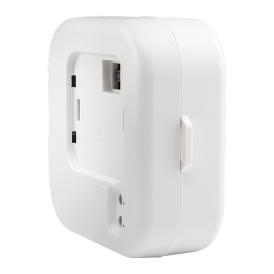
Page 119: Remove Or Attach The Backplate
The presence detectors are compatible with 4 in. square junction boxes, 4 in. round junction boxes, and 3 in. mud rings (not included). After the junction box is installed, follow the procedure for mounting the presence detectors. Product Manual — Doc. 9349B Crestron Zūm® Wired Solutions • 119... - Page 120 Pinch one spring tab to minimize it's width. b. Carefully lift the spring out of the housing. c. Repeat the process with the other spring tab. d. Discard the spring tabs. 120 • Crestron Zūm® Wired Solutions Product Manual — Doc. 9349B...
- Page 121 For presence detectors with additional output relays, connect the relays to a relay-input capable device before mounting the backplate to the junction box or mud ring. Relay connection applicable for the following presence detectors: ZUMLINK-IR-QUATTRO-DLS-RLY ZUMLINK-DT-QUATTRO-DLS-RLY Product Manual — Doc. 9349B Crestron Zūm® Wired Solutions • 121...
-
Page 122: Ceiling Mounting
A mounting hole 2.69 in. (68 mm) to 3 in. (76 mm) in diameter must be cut before mounting the presence detector to the ceiling. 1. Cut a mounting hole that is 2.69 in. (68 mm) to 3 in. (76 mm) in diameter. 122 • Crestron Zūm® Wired Solutions Product Manual — Doc. 9349B... - Page 123 Relay connection applicable for the following presence detectors: ZUMLINK-IR-QUATTRO-DLS-RLY ZUMLINK-DT-QUATTRO-DLS-RLY ZUMLINK-US-QUATTRO-DLS-RLY ZUMLINK-IR-QUATTRO-HD-DLS-RLY ZUMLINK-US-HALLWAY-DLS-RLY ZUMLINK-US-ONEWAY-DLS-RLY 3. Flip the backplate spring tabs to the vertical position and insert them into the mounting hole. Product Manual — Doc. 9349B Crestron Zūm® Wired Solutions • 123...
- Page 124 4. Attach the presence detector to the backplate. Refer to Remove or Attach the Backplate on page 119. 5. Wire the presence detector according to the Zūm Wired System Diagram on page 125 124 • Crestron Zūm® Wired Solutions Product Manual — Doc. 9349B...
- Page 125 Daisy-chain up to 20 Zūm Net devices (up to 328 ft (100 m) between Zūm Net devices) with purple CBL-CAT5E-ZUMNET-P RJ-45 cables (sold separately). Do not exceed three network switches between a ZUM-HUB4 and a Zūm Net device. System sensors communicate digitally via Zūm Link. Non-system sensors communicate via an analog connection on a Zūm Wired load controller.
-
Page 126: Hub Installation
Hub Installation Mount the ZUM-HUB4 and connect it to the network. The ZUM-HUB4 can be mounted into a rack or placed onto a flat surface. In the Box Qty. Description ZUM-HUB4, 4-Series™ Control Processor for Zūm® Lighting Control System Additional Items Connector, 4-Pin (2003576) Power Pack, 24VDC, 2.5A, 100-240VAC (2045873) -
Page 127: Place Onto A Flat Surface
Make Connections The hub has a dedicated Control Subnet that is used for communication between the control system and Crestron Ethernet devices. This subnet allows for dedicated communication between the control system and Crestron Ethernet devices without interferences from other network traffic on the LAN. - Page 128 Connections Zūm Wired System Diagram 128 • Crestron Zūm® Wired Solutions Product Manual — Doc. 9349B...
- Page 129 Daisy-chain up to 20 Zūm Net devices (up to 328 ft (100 m) between Zūm Net devices) with purple CBL-CAT5E-ZUMNET-P RJ-45 cables (sold separately). Do not exceed three network switches between a ZUM-HUB4 and a Zūm Net device. System sensors communicate digitally via Zūm Link. Non-system sensors communicate via an analog connection on a Zūm Wired load controller.
-
Page 130: Cable Accessory Installation
The ZUMLINK-SPLTR-RJ45 is a pass-through accessory that splits one Zūm link signal into two ports. Use Zūm link cable (CBL-CAT5E-ZUMLINK-P) to connect bidirectional RJ-45 ports to Zūm link devices, including Zūm link load controllers, sensors, or keypads. 130 • Crestron Zūm® Wired Solutions Product Manual — Doc. 9349B... -
Page 131: Zumlink-Conv-Cn Connections
(CBL-CAT5E-ZUMLINK-P) to connect the RJ-45 port to Zūm link sensors and keypad. Connect the Cresnet terminal block to legacy Cresnet lighting products, including a SpaceBuilder® system (such as the CL-SPACEBUILDER-DIN) or traditional processor panel. Product Manual — Doc. 9349B Crestron Zūm® Wired Solutions • 131... -
Page 132: Applications
Emergency Override Terminal Block Connections Terminal Description 24V power Emergency override Future use Ground Applications The following diagram is a sample application. Integrating a Legacy Lighting System into a Zūm System 132 • Crestron Zūm® Wired Solutions Product Manual — Doc. 9349B... - Page 133 Using a Zūm Link Splitter (ZUMLINK-SPLTR-RJ45) Product Manual — Doc. 9349B Crestron Zūm® Wired Solutions • 133...
-
Page 134: Power Supply Installation
Zūm Link ports on any Zūm Link or Zūm Net device. Also, do NOT connect the purple Zūm Net ports on the Zūm Net device to the orange Zūm Link ports on any Zūm Link device. These connections may damage network devices. 134 • Crestron Zūm® Wired Solutions Product Manual — Doc. 9349B... - Page 135 A 6 in. square, 3.5 in. deep box with conduit knockouts is recommended for the low-voltage cables and load controller. Product Manual — Doc. 9349B Crestron Zūm® Wired Solutions • 135...
- Page 136 2. Mount the power supply to the junction box using the included locknut. 3. Wire the power supply as shown in the following diagrams. ZUMLINK-JBOX-PSU Wiring to Other Zūm Link Devices ZUMLINK-JBOX-PSU Wiring 136 • Crestron Zūm® Wired Solutions Product Manual — Doc. 9349B...
- Page 137 ZUMLINK-JBOX-PSU Wiring to Meet Chicago Electric Code Product Manual — Doc. 9349B Crestron Zūm® Wired Solutions • 137...
- Page 138 Daisy-chain up to 20 Zūm Net devices (up to 328 ft (100 m) between Zūm Net devices) with purple CBL-CAT5E-ZUMNET-P RJ-45 cables (sold separately). Do not exceed three network switches between a ZUM-HUB4 and a Zūm Net device. System sensors communicate digitally via Zūm Link. Non-system sensors communicate via an analog connection on a Zūm Wired load controller.
-
Page 139: Rocker And Button Tree Installation
The bezel and rocker button release from the keypad. 3. Position the replacement rocker button/button tree on the keypad. Product Manual — Doc. 9349B Crestron Zūm® Wired Solutions • 139... - Page 140 LED hole with the LED on the keypad, and snap the bezel into place. For more information about installing the ZUMLINK-KP, refer to Keypad Installation on page 110. 140 • Crestron Zūm® Wired Solutions Product Manual — Doc. 9349B...
-
Page 141: Operation
Refer to the following operation sections. • Load Controller Operation • Universal Dimmer Load Controller Operation • Keypad Operation • Presence Detectors Operation Product Manual — Doc. 9349B Crestron Zūm® Wired Solutions • 141... -
Page 142: Load Controller Operation
LINK Green The load controller is actively being polled by the room primary load (solid) controller. TEST The local load is off. TEST Green The local load is on. 142 • Crestron Zūm® Wired Solutions Product Manual — Doc. 9349B... - Page 143 Assign a Load Controller as the Primary Controller on page 144. Performing a factory reset on any other Zūm Wired load controller or device in the space only restores the default settings for that device. Product Manual — Doc. 9349B Crestron Zūm® Wired Solutions • 143...
- Page 144 Reboot a Load Controller To reboot a load controller: 1. Tap the TEST button four times, then press and hold for five seconds. 2. Release the button when all LEDs flash red. 144 • Crestron Zūm® Wired Solutions Product Manual — Doc. 9349B...
- Page 145 NOTE: Performing a factory reset on a primary load controller erases all previous room logic to the default settings. Refer to Zūm App Configuration on page 152for configuring the device. Product Manual — Doc. 9349B Crestron Zūm® Wired Solutions • 145...
-
Page 146: Universal Dimmer Load Controller Operation
Universal Dimmer Load Controller Operation on page 146. 2. Press the DIM MODE button until the desired dimming mode is indicated by the REV, AUTO, FWD, or CENTER LED. 146 • Crestron Zūm® Wired Solutions Product Manual — Doc. 9349B... -
Page 147: Test The Loads
FILTER: Lights to indicate that the zero-cross filter is applying filtering to sync the AC line power. BASIC: Lights to indicate that the zero-cross filter is performing basic filtering. Product Manual — Doc. 9349B Crestron Zūm® Wired Solutions • 147... -
Page 148: Error States
2. Press the ZERO CROSS button. The BASIC or FILTER LED lights. BASIC LED: Indicates that basic filtering is being performed. FILTER LED: Indicates that the ZUMLINK-EXP-16A-DIMU is using filters to sync the AC line power. 148 • Crestron Zūm® Wired Solutions Product Manual — Doc. 9349B... -
Page 149: Keypad Operation
Lower: Assigned load controllers lower. Recall Scene 1 - Scene 16: Assigned load controllers recall the behavior set for the specified scene. Refer to Zūm App Configuration on page 152for configuring the device. Product Manual — Doc. 9349B Crestron Zūm® Wired Solutions • 149... -
Page 150: Presence Detectors Operation
Off after grace period delay Refer to Zūm App Configuration on page 152for configuring the device. To adjust the presence detector sensitivity, refer to Sensor Test Mode on page 213. 150 • Crestron Zūm® Wired Solutions Product Manual — Doc. 9349B... -
Page 151: Configuration
Configuration Before using a Zūm Wired device, ensure it is updated with the latest firmware. Check for the latest firmware at www.crestron.com/firmware. Load the firmware onto the device using Crestron Toolbox™ software, the ZUM-HUB4 web interface (refer to Version Management on page 255), or the Zūm app (refer to... -
Page 152: Zūm App Configuration
The following sections provide information for configuring Zūm Wired devices with the app. • Update Firmware with the Zūm App • Load Controllers Zūm App Configuration • Keypad Zūm App Configuration • Presence Detector App Configuration 152 • Crestron Zūm® Wired Solutions Product Manual — Doc. 9349B... -
Page 153: Update Firmware With The Zūm App
Tap Download Firmware to load the firmware to the app. The Room Firmware window message changes when the firmware is successfully downloaded. The Zūm app is now ready to connect to the Zūm space and start updating outdated devices. Product Manual — Doc. 9349B Crestron Zūm® Wired Solutions • 153... - Page 154 NOTE: Firmware is enabled when the Zūm space device firmware is lower than the version downloaded in Nearby Rooms. When the Zūm space device firmware is up to date, Firmware option is disabled. 154 • Crestron Zūm® Wired Solutions Product Manual — Doc. 9349B...
- Page 155 Zūm app back to Nearby Rooms. Refer to steps 2 through 5. NOTE: The number next to the device type indicates the number of devices of that type that need to be updated in that Zūm space. Product Manual — Doc. 9349B Crestron Zūm® Wired Solutions • 155...
- Page 156 (steps 2 through 4). 6. When all of the devices are updated in a Zūm space, repeat the process for every Zūm space listed in Nearby Rooms. 156 • Crestron Zūm® Wired Solutions Product Manual — Doc. 9349B...
-
Page 157: Load Controllers Zūm App Configuration
Zūm App Main Screen From the Nearby Rooms screen, tap the desired room to open the Main screen. The following sections describe the actions available for each area of the Main screen. Product Manual — Doc. 9349B Crestron Zūm® Wired Solutions • 157... - Page 158 Scenes: Allow keypad access to the scene by selecting or deselecting the checkbox. Determine the state of the load when the scene is recalled by clicking the toggle on or off. 158 • Crestron Zūm® Wired Solutions Product Manual — Doc. 9349B...
- Page 159 Lower: Assigned load controllers lower. Recall Scene 1 - Scene 16: Assigned load controllers recall the behavior set for the specified scene. Export to Hub: Name and send information to ZUM-HUB4 for macro actions. Load Shedding: Set the maximum levels for load shedding.
- Page 160 Tap the device to edit or review the device details: Edit Name. Review the Model, Serial Number, Status, and edit the device settings. 5. Current Template Settings: Choose Open room template, Save room template, or Share room template. 160 • Crestron Zūm® Wired Solutions Product Manual — Doc. 9349B...
- Page 161 1. Assign the photocell component of a load controller to the load controller. 2. Send the new configuration to the space. 3. Adjust the light level in the space. 4. Calibrate Daylighting. Product Manual — Doc. 9349B Crestron Zūm® Wired Solutions • 161...
- Page 162 1. Assign the photocell component to the load controller that will participate in Daylighting. a. From the Main screen, click Configuration. b. Click Load Controllers. c. Click the desired load controller. d. For Photo, select a photocell from the drop-down menu. 162 • Crestron Zūm® Wired Solutions Product Manual — Doc. 9349B...
- Page 163 A confirmation window opens stating that the app will disconnect from the room. Click OK to continue or Cancel to close without sending the configuration. The Retrieving Data Map screen displays. Product Manual — Doc. 9349B Crestron Zūm® Wired Solutions • 163...
- Page 164 Select Scene 1. Daylighting is only available for Scene 1. d. Adjust the loads in the space to the appropriate level based on the amount of natural light. NOTE: DO NOT click Save current levels. 164 • Crestron Zūm® Wired Solutions Product Manual — Doc. 9349B...
- Page 165 During Daylight calibration, the lights in the space will turn full on, turn off, and then back on with the Daylighting settings. Whenever Scene 1 is recalled, the Daylighting settings are initiated. Product Manual — Doc. 9349B Crestron Zūm® Wired Solutions • 165...
- Page 166 Zūm App Main Screen From the Nearby Rooms screen, tap the desired room to open the Main screen. The following sections describe the actions available for each area of the Main screen. 166 • Crestron Zūm® Wired Solutions Product Manual — Doc. 9349B...
- Page 167 Scenes: Allow keypad access to the scene by selecting or deselecting the checkbox. Determine the state of the load when the scene is recalled by clicking the toggle on or off. Product Manual — Doc. 9349B Crestron Zūm® Wired Solutions • 167...
- Page 168 Lower: Assigned load controllers lower. Recall Scene 1 - Scene 16: Assigned load controllers recall the behavior set for the specified scene. Export to Hub: Name and send information to ZUM-HUB4 for macro actions. Load Shedding: Set the maximum levels for load shedding.
- Page 169 Tap the device to edit or review the device details: Edit Name. Review the Model, Serial Number, Status, and edit the device settings. 5. Current Template Settings: Choose Open room template, Save room template, or Share room template. Product Manual — Doc. 9349B Crestron Zūm® Wired Solutions • 169...
- Page 170 1. Assign the photocell component of a load controller to the load controller. 2. Send the new configuration to the space. 3. Adjust the light level in the space. 4. Calibrate Daylighting. 170 • Crestron Zūm® Wired Solutions Product Manual — Doc. 9349B...
- Page 171 1. Assign the photocell component to the load controller that will participate in Daylighting. a. From the Main screen, click Configuration. b. Click Load Controllers. c. Click the desired load controller. d. For Photo, select a photocell from the drop-down menu. Product Manual — Doc. 9349B Crestron Zūm® Wired Solutions • 171...
- Page 172 A confirmation window opens stating that the app will disconnect from the room. Click OK to continue or Cancel to close without sending the configuration. The Retrieving Data Map screen displays. 172 • Crestron Zūm® Wired Solutions Product Manual — Doc. 9349B...
- Page 173 Select Scene 1. Daylighting is only available for Scene 1. d. Adjust the loads in the space to the appropriate level based on the amount of natural light. NOTE: DO NOT click Save current levels. Product Manual — Doc. 9349B Crestron Zūm® Wired Solutions • 173...
- Page 174 During Daylight calibration, the lights in the space will turn full on, turn off, and then back on with the Daylighting settings. Whenever Scene 1 is recalled, the Daylighting settings are initiated. 174 • Crestron Zūm® Wired Solutions Product Manual — Doc. 9349B...
- Page 175 Load Controllers Zūm App Configuration on page 157 for more information. 4. Assign drivers (Load Controllers Zūm App Configuration on page 157) To begin the commissioning process, tap DALI Controllers in Configuration. Product Manual — Doc. 9349B Crestron Zūm® Wired Solutions • 175...
- Page 176 DALI load controller can be controlled in unison. In Groups mode, individual drivers can be placed in groups for granular control over the devices. To confirm the room's operating mode: 176 • Crestron Zūm® Wired Solutions Product Manual — Doc. 9349B...
- Page 177 To change the Operating mode: NOTE: Changing the Operating mode affects keypad programming assignments. Review the assignments after implementing the change. 1. Tap the current Operating mode to open the Operating mode menu. Product Manual — Doc. 9349B Crestron Zūm® Wired Solutions • 177...
- Page 178 Tap Delete and Address All to delete any driver information and begin the addressing process. When the confirmation window opens, tap OK to continue or Cancel to exit without readdressing the system. 178 • Crestron Zūm® Wired Solutions Product Manual — Doc. 9349B...
- Page 179 DALI groups: Tap the check box next to the desired DALI group. Tap Save to save the changes or tap Back to return to the previous screen without saving. Product Manual — Doc. 9349B Crestron Zūm® Wired Solutions • 179...
- Page 180 Add a group: Opens the same screen as Load Controllers Zūm App Configuration on page 157. 180 • Crestron Zūm® Wired Solutions Product Manual — Doc. 9349B...
- Page 181 Add a Group Tap Save to save the DALI group. The previous screen appears with the new DALI group listed under Group Assignments. Product Manual — Doc. 9349B Crestron Zūm® Wired Solutions • 181...
- Page 182 Group Min Level: Displays the value set in View Dimming Properties > Min Level (0-45%). Delete this Group: Tap to delete the DALI group. Delete this Group is only enabled after all drivers are removed from the group. 182 • Crestron Zūm® Wired Solutions Product Manual — Doc. 9349B...
- Page 183 Group Parameters: Tap to access the Group Parameters. Current scene Daylighting Output Level Override Occupancy Vacancy Vicinity Photo Product Manual — Doc. 9349B Crestron Zūm® Wired Solutions • 183...
- Page 184 On Fade Time (0.25-30.00 secs): Set the amount of time to fade from the current light level to the On scene. Off Fade Time (0.25-30.00 secs): Set the amount of time to fade from the current light level to the Off scene. 184 • Crestron Zūm® Wired Solutions Product Manual — Doc. 9349B...
- Page 185 If missing drivers are detected, Clear all missing drivers is active. Tap Clear all missing drivers to delete the addressed information. Return to Addressing and tap Address New / Resolve Conflicts. Product Manual — Doc. 9349B Crestron Zūm® Wired Solutions • 185...
- Page 186 Number of drivers that failed Presence of unassigned drivers Tap Test result details to view the driver address and how many times out of 10 the driver did not respond to a ping. 186 • Crestron Zūm® Wired Solutions Product Manual — Doc. 9349B...
- Page 187 Product Manual — Doc. 9349B Crestron Zūm® Wired Solutions • 187...
- Page 188 Zūm App Main Screen From the Nearby Rooms screen, tap the desired room to open the Main screen. The following sections describe the actions available for each area of the Main screen. 188 • Crestron Zūm® Wired Solutions Product Manual — Doc. 9349B...
- Page 189 Scenes: Allow keypad access to the scene by selecting or deselecting the checkbox. Determine the state of the load when the scene is recalled by clicking the toggle on or off. Product Manual — Doc. 9349B Crestron Zūm® Wired Solutions • 189...
- Page 190 Lower: Assigned load controllers lower. Recall Scene 1 - Scene 16: Assigned load controllers recall the behavior set for the specified scene. Export to Hub: Name and send information to ZUM-HUB4 for macro actions. Load Shedding: Set the maximum levels for load shedding.
- Page 191 Tap the device to edit or review the device details: Edit Name. Review the Model, Serial Number, Status, and edit the device settings. 5. Current Template Settings: Choose Open room template, Save room template, or Share room template. Product Manual — Doc. 9349B Crestron Zūm® Wired Solutions • 191...
- Page 192 1. Assign the photocell component of a load controller to the load controller. 2. Send the new configuration to the space. 3. Adjust the light level in the space. 4. Calibrate Daylighting. 192 • Crestron Zūm® Wired Solutions Product Manual — Doc. 9349B...
- Page 193 1. Assign the photocell component to the load controller that will participate in Daylighting. a. From the Main screen, click Configuration. b. Click Load Controllers. c. Click the desired load controller. d. For Photo, select a photocell from the drop-down menu. Product Manual — Doc. 9349B Crestron Zūm® Wired Solutions • 193...
- Page 194 A confirmation window opens stating that the app will disconnect from the room. Click OK to continue or Cancel to close without sending the configuration. The Retrieving Data Map screen displays. 194 • Crestron Zūm® Wired Solutions Product Manual — Doc. 9349B...
- Page 195 Select Scene 1. Daylighting is only available for Scene 1. d. Adjust the loads in the space to the appropriate level based on the amount of natural light. NOTE: DO NOT click Save current levels. Product Manual — Doc. 9349B Crestron Zūm® Wired Solutions • 195...
- Page 196 During Daylight calibration, the lights in the space will turn full on, turn off, and then back on with the Daylighting settings. Whenever Scene 1 is recalled, the Daylighting settings are initiated. 196 • Crestron Zūm® Wired Solutions Product Manual — Doc. 9349B...
- Page 197 2. Select Load Controllers. A list of load controllers appears. 3. Select the universal dimmer from the list of load controllers. 4. Select the universal dimmer load controller component to open the load controller settings. Product Manual — Doc. 9349B Crestron Zūm® Wired Solutions • 197...
- Page 198 5. Select View Dimmer Values to open the Dimming Properties. 198 • Crestron Zūm® Wired Solutions Product Manual — Doc. 9349B...
- Page 199 6. Select Advanced to open the Advanced Properties. Product Manual — Doc. 9349B Crestron Zūm® Wired Solutions • 199...
- Page 200 Crestron True Blue Technical Support representative. By default, Auto is selected. To change the phase: 1. Select the SET PHASE menu to open the options: Forward, Reverse, Center, and Auto. 200 • Crestron Zūm® Wired Solutions Product Manual — Doc. 9349B...
- Page 201 NOTE: If the Back button is selected while changing the Advanced Properties settings, the following warning displays. Select Leave to leave without applying a change or Stay to apply the change. Product Manual — Doc. 9349B Crestron Zūm® Wired Solutions • 201...
- Page 202 By default, Filtered is selected and is strongly recommended for best performance. To change the zero-cross. 1. Select the SET ZERO-CROSS menu to open the options: Basic and Filtered. 202 • Crestron Zūm® Wired Solutions Product Manual — Doc. 9349B...
- Page 203 NOTE: If the Back button is selected while changing the Advanced Properties settings, the following warning displays. Select Leave to leave without applying a change or Stay to apply the change. Product Manual — Doc. 9349B Crestron Zūm® Wired Solutions • 203...
-
Page 204: Keypad Zūm App Configuration
Zūm App Main Screen From the Nearby Rooms screen, tap the desired room to open the Main screen. The following sections describe the actions available for each area of the Main screen. 204 • Crestron Zūm® Wired Solutions Product Manual — Doc. 9349B... - Page 205 Scenes: Allow keypad access to the scene by selecting or deselecting the checkbox. Determine the state of the load when the scene is recalled by clicking the toggle on or off. Product Manual — Doc. 9349B Crestron Zūm® Wired Solutions • 205...
- Page 206 Lower: Assigned load controllers lower. Recall Scene 1 - Scene 16: Assigned load controllers recall the behavior set for the specified scene. Export to Hub: Name and send information to ZUM-HUB4 for macro actions. Load Shedding: Set the maximum levels for load shedding.
- Page 207 Tap the device to edit or review the device details: Edit Name. Review the Model, Serial Number, Status, and edit the device settings. 5. Current Template Settings: Choose Open room template, Save room template, or Share room template. Product Manual — Doc. 9349B Crestron Zūm® Wired Solutions • 207...
- Page 208 NOTE: Changes made in the app are not sent to the room until they are deployed using the Send configuration to room button. 7. Revert changes: Restore all non-deployed changes made since launching the app. 208 • Crestron Zūm® Wired Solutions Product Manual — Doc. 9349B...
-
Page 209: Presence Detector App Configuration
Zūm App Main Screen From the Nearby Rooms screen, tap the desired room to open the Main screen. The following sections describe the actions available for each area of the Main screen. Product Manual — Doc. 9349B Crestron Zūm® Wired Solutions • 209... - Page 210 Scenes: Allow keypad access to the scene by selecting or deselecting the checkbox. Determine the state of the load when the scene is recalled by clicking the toggle on or off. 210 • Crestron Zūm® Wired Solutions Product Manual — Doc. 9349B...
- Page 211 Lower: Assigned load controllers lower. Recall Scene 1 - Scene 16: Assigned load controllers recall the behavior set for the specified scene. Export to Hub: Name and send information to ZUM-HUB4 for macro actions. Load Shedding: Set the maximum levels for load shedding.
- Page 212 Tap the device to edit or review the device details: Edit Name. Review the Model, Serial Number, Status, and edit the device settings. 5. Current Template Settings: Choose Open room template, Save room template, or Share room template. 212 • Crestron Zūm® Wired Solutions Product Manual — Doc. 9349B...
- Page 213 To access the Sensor Test Mode from the Zūm app Main Screen, tap Configuration and tap Occupancy Sensors. A list of occupancy sensor components displays, including the occupancy sensor components for load controllers and presence detectors. Product Manual — Doc. 9349B Crestron Zūm® Wired Solutions • 213...
- Page 214 In this example, the occupancy sensor component for the presence detector is the ZUMLINK-US-ONEWAY-DLS-RLY-0074-2. The other occupancy sensors listed are for load controllers. 214 • Crestron Zūm® Wired Solutions Product Manual — Doc. 9349B...
- Page 215 This screen enables users to make adjustments and confirm the expected detection sensitivities. For presence detectors, the radio button indicates whether the Ultrasonic or Infrared technology triggered. For non-system presence detectors, the room status is identified as Occupied or Vacant. Product Manual — Doc. 9349B Crestron Zūm® Wired Solutions • 215...
- Page 216 Test Mode in the Zūm app. Refer to Sensor Test Mode on page 213. 2. In the Zūm app, locate the desired presence detector(s) in the list and tap Sensor Test Mode to begin the test. 216 • Crestron Zūm® Wired Solutions Product Manual — Doc. 9349B...
- Page 217 NOTE: The radio buttons light momentarily to identify the presence detector and technology triggered. Use the Latch Motion Sensor Indicators toggle to retain the radio button with the last motion detected. The Clear Motion Indicator button resets the radio buttons. Product Manual — Doc. 9349B Crestron Zūm® Wired Solutions • 217...
- Page 218 5. Move the Sensitivity or Range slider to the desired position. 6. To test the new setting, click to return to Sensor Test Mode. 7. Repeat the process from step 3 until the desired sensitivity is attained. 218 • Crestron Zūm® Wired Solutions Product Manual — Doc. 9349B...
-
Page 219: Hub Web Interface
Hub Web Interface The ZUM-HUB4 is configured using the web interface. Connect to the device by entering the device hostname into a web browser. The hostname is comprised of "ZUM-HUB4-" followed by the entire MAC address (e.g., ZUM-HUB4-00107FCA1112)“ZUM-FL-” and the last 8 digits of the MAC address (e.g., ZUM-FL-7F8764BF). -
Page 220: Web Interface Overview
The Category View lists room categories and rooms (in the Rooms tab) that have been discovered by the ZUM-HUB4. Room Categories are intended to be groupings of all rooms that are a similar type (for example, office or conference rooms) to provide easy monitoring and control. - Page 221 Manage External Controls on page 260 Manage Commissioning on page 264 Global Settings and Actions for the ZUM-HUB4 Apply settings that effect all devices discovered by the ZUM-HUB4 regardless of the room, room category, or floor the device is assigned. ZUM-HUB4 actions:...
- Page 222 Navigation Toggle Click to collapse or the Category View, System View, Setting Views, and the global ZUM-HUB4 settings. Device Information and Status View the Demand Response status, system alerts, help information, or sign out of the web interface. Refer to Review Device Information and Status on page 267.
-
Page 223: Web Interface Configuration
After using the Zūm app to setup Zūm spaces and logging into web interface, configure the ZUM-HUB4: Related topics: Zūm App Configuration on page 152 Hub Web Interface on page 219 Product Manual — Doc. 9349B Crestron Zūm® Wired Solutions • 223... - Page 224 3. Select the type of rooms you want to discover. 4. Click Discover to Discover rooms or close the window. During the discover process, a Stop button displays as an option to stop discovering. 224 • Crestron Zūm® Wired Solutions Product Manual — Doc. 9349B...
- Page 225 Add a Room Category To create a room category: 1. Click the menu beside the ZUM-HUB4. 2. Click Add Category. 3. Type the name of the Room Category. 4. Click to save the Room Category or to cancel. For more information about Room Categories, refer to Manage Room Categories.
- Page 226 1. Click the menu beside the Room Category name. 2. Click Rename. 3. Click to save the Room Category or to cancel. For more information about Room Categories, refer to Manage Room Categories. 226 • Crestron Zūm® Wired Solutions Product Manual — Doc. 9349B...
- Page 227 Turn On/Off All Discovered Devices To turn all devices on/off: 1. Open the Category View. 2. Click the menu beside the ZUM-HUB4. 3. Click All Off or All On. Turn On/Off a Room Category To turn all devices on/off in a Room Category: 1.
- Page 228 Turn On/Off a Room You can turn a specific room on/off using the Control Room window, but this option provides more detailed settings. Refer to Control a Room on page 239. 228 • Crestron Zūm® Wired Solutions Product Manual — Doc. 9349B...
-
Page 229: Set The Bluetooth Pin
Set the Bluetooth PIN for All Discovered Devices To set the Bluetooth PIN for all devices: 1. Open the Category View. 2. Click the menu beside the ZUM-HUB4. 3. Click Bluetooth PIN. 4. Set the PIN (0 to 9999). 5. Click to save or to cancel. - Page 230 Set the Bluetooth PIN for a Floor To set the Bluetooth PIN for devices on a floor: 1. Open the System View. 2. Click the menu beside the Floor name. 3. Click Bluetooth PIN. 230 • Crestron Zūm® Wired Solutions Product Manual — Doc. 9349B...
- Page 231 4. Set the PIN (0 to 9999). 5. Click to save or to cancel. Product Manual — Doc. 9349B Crestron Zūm® Wired Solutions • 231...
-
Page 232: Configure The Demand Response Mode And Level
Configure Demand Response Mode To manually turn Demand Response Mode on or off: 1. Click the Actions menu. 2. Click Demand Response Mode. The Configure Demand Response Mode window opens. 232 • Crestron Zūm® Wired Solutions Product Manual — Doc. 9349B... - Page 233 3. Click the toggle turn Demand Response Mode on or off. If a GLS-SIM has been discovered by the ZUM-HUB4, the GLS-SIM status is represented as Offline or Online. 4. Click Save to save the settings or Cancel to close the window without saving.
- Page 234 3. For Demand Response, set the level (0 to 100). 4. Click Send to send changes to the room, or close the Control Room window to discard unsaved changes. 234 • Crestron Zūm® Wired Solutions Product Manual — Doc. 9349B...
- Page 235 1. Open the System View. 2. Click the menu beside the Floor name. 3. Click Demand Response Level. 4. Set the light level (0 to 100). 5. Click to save or to cancel. Product Manual — Doc. 9349B Crestron Zūm® Wired Solutions • 235...
- Page 236 Manage Rooms The Rooms tabs lists the Rooms discovered by the ZUM-HUB4 or the rooms assigned to a selected Room Category. Use the Rooms tab search for a room, delete rooms, reassign room categories, edit a room name, view room details, or control a room. Access the Rooms tab through either the Category View or the System View tabs.
- Page 237 Last Occupancy Status Changed: Displays the date and time of the last Occupancy Status change Click to expand the room to display information regarding the components. The Name, Model, Serial Number, Firmware Version, and Status of the devices are defined. Product Manual — Doc. 9349B Crestron Zūm® Wired Solutions • 237...
- Page 238 Find a Room on the ZUM-HUB4 For a ZUM-HUB4 that has a large number of rooms, use the search feature to find a room name. To search for a room: 1. Click on the ZUM-HUB4 or on a Room Category.
- Page 239 Bluetooth PIN, or set the Demand Response level for a specific room. 1. Click on the ZUM-HUB4 or on a Room Category. 2. For the desired room, click the to open the Control Room options.
- Page 240 2. Click Send to send changes to the room, or close the Control Room to discard unsaved changes. Refer to Configure the Demand Response Mode and Level on page 232 for more information. 240 • Crestron Zūm® Wired Solutions Product Manual — Doc. 9349B...
-
Page 241: Schedule Room Behavior
3. Click the desired date in the calendar. If necessary, change the month and year using the drop-down menus, and then click the desired date. A menu displays a list of the available Day Patterns. 4. Select the desired Day Pattern. Product Manual — Doc. 9349B Crestron Zūm® Wired Solutions • 241... - Page 242 2. Click Yes to delete the Day Pattern, or click No to keep the Day Pattern. NOTE: A Default Day Pattern (such as Holidays, Weekend, and Workdays) cannot be deleted. 242 • Crestron Zūm® Wired Solutions Product Manual — Doc. 9349B...
- Page 243 State Schedule and Sunrise/Sunset Schedule. The Room State Schedule opens by default. Room State Schedule Use the Room State Schedule window to modify the pattern of Room States in each Category for the selected Day Pattern. Product Manual — Doc. 9349B Crestron Zūm® Wired Solutions • 243...
- Page 244 3. Click Ok to save the changes or Cancel to close the window without saving. Change the assigned time: Click and drag the event block to the desired time within the time table. 244 • Crestron Zūm® Wired Solutions Product Manual — Doc. 9349B...
- Page 245 Sunrise/Sunset Schedule The ZUM-HUB4 determines sunrise and sunset based on the location set in Location on page 256 settings. The Sunrise/Sunset Schedule assigns a Room State to a Room Category based on the Day Pattern and the sunrise or sunset. Only one Sunrise event and one Sunset event can be set for a Room Category per day.
- Page 246 Plug Loads: Select On to turn on the Plug loads, Off to turn off the Plug Loads, or Unaffected to use the setting of the previous event. 3. Click Cancel to close the window without saving, or Add to add the Room State. 246 • Crestron Zūm® Wired Solutions Product Manual — Doc. 9349B...
- Page 247 2. Click Yes to delete the Room State, or click No to keep the Day Pattern. NOTE: A Default Room State (such as Automatic Mode and Default - Use Occupancy) cannot be deleted. Product Manual — Doc. 9349B Crestron Zūm® Wired Solutions • 247...
- Page 248 Holiday. A confirmation window opens. 2. Click Yes to delete the Holiday, or click No to keep the Holiday. NOTE: A default Holiday cannot be deleted. 248 • Crestron Zūm® Wired Solutions Product Manual — Doc. 9349B...
- Page 249 Schedule tab. When the toggle is off, the default Day Pattern is applied instead. Observed: Select a date to observe the holiday. 3. Click Add to add the Holiday or Cancel to close the window. Product Manual — Doc. 9349B Crestron Zūm® Wired Solutions • 249...
-
Page 250: Manage Floors
Manage Floors Rooms must be discovered by the ZUM-HUB4 before performing any procedure in this section. Refer to Discover Rooms on page 224. Access Floors in the System View. To manage a Floor, refer to the following information: Turn On/Off a Floor on page 228... -
Page 251: Manage Devices
Wired and Wireless. Expand the Wireless menu to view and edit wireless devices. Expand the Wired menu to view and edit wired devices. Rooms must be discovered by the ZUM-HUB4 before performing any procedure in this section. Refer to Discover Rooms on page 224. - Page 252 ID to a gateway helps gateways discover wireless devices with the matching Zone ID. Set a device's Zone ID in the Zūm app before discovering the devices on the ZUM-HUB4. The Zone ID drop-down menu options are letter groupings AA to AZ and BA to BF.
- Page 253 -40 to + 200 and Disabled. The Floor ID can be negative to indicate a floor below ground or positive to indicate a level above ground. Disabled categorizes the load controller to Unassigned Floor. Product Manual — Doc. 9349B Crestron Zūm® Wired Solutions • 253...
- Page 254 Model: Displays the device model. Serial Number: Displays the component's serial number. Firmware Version: Displays the component's firmware version. Status: Displays Online or Offline to show the component's status. 254 • Crestron Zūm® Wired Solutions Product Manual — Doc. 9349B...
- Page 255 Crestron services. Version Management Allows you to check for firmware updates for the ZUM-HUB4 and connected devices. Firmware updates for battery powered devices may take up to 24 hours. To update firmware: 1. Open Settings View.
- Page 256 NOTE: Changing these settings requires an immediate system reboot. A confirmation windows opens. Click Yes to reboot or No to close the window. 256 • Crestron Zūm® Wired Solutions Product Manual — Doc. 9349B...
- Page 257 NOTE: Changing these settings requires an immediate system reboot. A confirmation windows opens. Click Yes to reboot or No to close the window. Product Manual — Doc. 9349B Crestron Zūm® Wired Solutions • 257...
- Page 258 5. Click Save to save the new user or Cancel to exit without creating a new user. Configure an Existing User To configure an existing User: 1. Open Settings View. 2. Click Users. 258 • Crestron Zūm® Wired Solutions Product Manual — Doc. 9349B...
- Page 259 NOTES: SIMPL+® software modules are provided for use in commissioning a Crestron control system to work with the ZUM-HUB4. The software modules run within the control system program and provide virtual connections for all the necessary intersystem control signals. A separate dedicated module is required for each external and mirrored room.
- Page 260 SIMPL+® software modules are provided for use in commissioning a Crestron control system to work with the ZUM-HUB4. The software modules run within the control system program and provide virtual connections for all the necessary intersystem control signals. A separate dedicated module is required for each external and mirrored room.
- Page 261 The BACnet tab displays the system settings to establish a connection with the BMS (building management system). To configure BACnet service: 1. Open Settings View. 2. Click the External Controls tab and expand the BACnet Configuration menu. Product Manual — Doc. 9349B Crestron Zūm® Wired Solutions • 261...
- Page 262 NOTE: Use the search to find a specific room. BACnet Service: Click the toggle to turn the BACnet service on or off. Host ID: The ID that the ZUM-HUB4 uses when communicating with the BACnet system. Port Number: The port number that is used when communicating with the BACnet system.
- Page 263 Product Manual — Doc. 9349B Crestron Zūm® Wired Solutions • 263...
- Page 264 2. Click the Commissioning tab and expand the Template Management menu. 3. If necessary, use the Search bar to find a room template. 4. Click 5. Type the new name. 264 • Crestron Zūm® Wired Solutions Product Manual — Doc. 9349B...
- Page 265 3. Select a room or multiple rooms. If necessary, use the Search bar to find a room. 4. From the Select a template drop-down menu, choose the desired template. 5. Click Apply Template. When the template is successfully applied, the template is now pending. Product Manual — Doc. 9349B Crestron Zūm® Wired Solutions • 265...
- Page 266 Mapping and Template Deployment menu. If a mapping file has been created in an external file, use the Import Mapping File button to navigate to the mapping and import the file. 266 • Crestron Zūm® Wired Solutions Product Manual — Doc. 9349B...
- Page 267 View the Demand Response status, system alerts, help information, or sign out of the web interface. Demand Response Status Demand Response is enabled. Demand Response is disabled. System Information Displays system alerts. Help Click to view the help file. Product Manual — Doc. 9349B Crestron Zūm® Wired Solutions • 267...
- Page 268 Sign Out Click to bring up the Sign Out pop-up. Click Sign Out to log out of the ZUM-HUB4. 268 • Crestron Zūm® Wired Solutions Product Manual — Doc. 9349B...
- Page 269 To reboot the ZUM-HUB4: 1. Click the Actions menu 2. Click Reboot. The Confirmation window opens. 3. Click Yes to Reboot or No to close the window without rebooting. Product Manual — Doc. 9349B Crestron Zūm® Wired Solutions • 269...
-
Page 270: Resources
Resources Below are resources provided for Crestron Zūm® Wired Solutions. NOTE: You may need to provide your Crestron.com web account credentials when prompted to access some of the following resources. Crestron Support and Training Crestron True Blue Support Crestron Resource Library Crestron Online Help (OLH) Crestron Training Institute (CTI) Portal... - Page 271 Title 24 2019 Education Applications Healthcare Applications Hospitality Applications Office Applications Restaurant Applications Retail Applications IECC 2018 Education Applications Healthcare Applications Hospitality Applications Office Applications Restaurant Applications Retail Applications Product Manual — Doc. 9349B Crestron Zūm® Wired Solutions • 271...
-
Page 272: Models
Models Below are the available products for Crestron Zūm® Wired Solutions. Load Controllers Part Number Model Description 6511166 ZUMNET-JBOX-16A-LV Zūm® Wired J-Box Load Controller, 0-10V Dimmer, 16A, 100-277V with Net and Link Communication 6511170 ZUMNET-JBOX-DALI Zūm® Wired J-Box Controller with DALI® Drivers, 120-... -
Page 273: Hub And Kits
4-Series™ Control Processor for Zūm® Lighting Control System with Wireless Gateway and Power Supply 6512646 ZUML-HUB4-PAK Zūm® Lighting Control Processor Panel, Basic 6512647 ZUML-HUB4-CN-PAK Zūm® Lighting Control Processor Panel, Expanded Product Manual — Doc. 9349B Crestron Zūm® Wired Solutions • 273... -
Page 274: Software
Software Part Number Model Description CRESTRON-ZUM Crestron Zūm® Lighting Configuration App 3002182 SW-HUB4-PROG Custom Program License for ZUM-HUB4 Power Supply Part Number Model Description 6512056 ZUMLINK-JBOX-PSU Zūm® Wired J-Box Power Supply Cables Part Number Model Description 6511388 CBL-CAT5E-ZUMNET-P-25 CAT5e Cable with Net Communication for LAN Wiring Zūm®... -
Page 275: Cable Accessories
Two Button Tree with Bezel for Zūm® Light Control Keypads ENGRAVED (ZUMLINK-KP), Engraved, R 6511203 ZUMLINK-BTN4-W Four Button Tree with Bezel for Zūm® Light Control Keypads ENGRAVED (ZUMLINK-KP), Engraved, White Product Manual — Doc. 9349B Crestron Zūm® Wired Solutions • 275... - Page 276 Two Button Tree with Bezel for Zūm® Light Control Keypads (ZUMLINK-KP), Pad Printed, Gray 6512421 ZUMLINK-BTN2-R Two Button Tree with Bezel for Zūm® Light Control Keypads (ZUMLINK-KP), Pad Printed, Red 276 • Crestron Zūm® Wired Solutions Product Manual — Doc. 9349B...
- Page 277 ZUMLINK-BTNR-A Rocker Button with Bezel for Zūm® Light Control Keypads BLANK (ZUMLINK-KP), Blank, Almond 6511191 ZUMLINK-BTNR-G Rocker Button with Bezel for Zūm® Light Control Keypads BLANK (ZUMLINK-KP), Blank, Gray Product Manual — Doc. 9349B Crestron Zūm® Wired Solutions • 277...
- Page 278 Eight Button Tree with Bezel for Zūm® Light Control Keypads BLANK (ZUMLINK-KP), Blank, Black 6512591 ZUMLINK-BTN8-A Eight Button Tree with Bezel for Zūm® Light Control Keypads BLANK (ZUMLINK-KP), Blank, Almond 278 • Crestron Zūm® Wired Solutions Product Manual — Doc. 9349B...
- Page 279 Eight Button Tree with Bezel for Zūm® Light Control Keypads BLANK (ZUMLINK-KP), Blank, Gray 6512593 ZUMLINK-BTN8-R Eight Button Tree with Bezel for Zūm® Light Control Keypads BLANK (ZUMLINK-KP), Blank, Red Product Manual — Doc. 9349B Crestron Zūm® Wired Solutions • 279...
- Page 280 This page is intentionally left blank. Product Manual — Doc. 9349B Crestron Zūm® Wired Solutions • 280...
- Page 281 Product Manual — Doc. 9349B Crestron Electronics, Inc. (2055411) 15 Volvo Drive, Rockleigh, NJ 07647 04/06/23 Tel: 888.CRESTRON Specifications subject to Fax: 201.767.7656 change without notice. www.crestron.com...
Need help?
Do you have a question about the Zum and is the answer not in the manual?
Questions and answers