Crestron 4 Series Product Manual
Hide thumbs
Also See for 4 Series:
- Product manual (74 pages) ,
- Quick start manual (12 pages) ,
- Quick start (5 pages)
Table of Contents
Advertisement
Advertisement
Table of Contents

Related Manuals for Crestron 4 Series


Summary of Contents for Crestron 4 Series
- Page 1 CP4 and CP4N 4-Series™ Control Systems Product Manual Crestron Electronics, Inc.
- Page 2 Crestron disclaims any proprietary interest in the marks and names of others. Crestron is not responsible for errors in typography or photography.
-
Page 3: Table Of Contents
Contents Overview Features CP4 Features CP4N Features Physical Description Specifications CP4 Specifications Product Specifications Dimension Drawings CP4N Specifications Product Specifications Dimension Drawings Installation Install the Control System Rack Mounting Surface Placement Connect the Control System Connect the Control Subnet (CP4N Only) Configure the Control System Configuration via IP Address Configuration via XiO Cloud Create an Admin Account... - Page 4 Services Cloud Settings Auto Update AV Framework Security Current User Users Groups 802.1x Configuration Connect to XiO Cloud Service Programming Resources Crestron Support and Training Programmer and Developer Resources Product Certificates Related Documentation iv • Contents Product Manual — Doc. 9214A...
-
Page 5: Overview
4-Series™ control engine. The CP4 and CP4N are designed to integrate and automate technology within any modern networked home, commercial building, or government facility. An isolated control subnet port provides a Gigabit Ethernet LAN dedicated to Crestron® devices (CP4N only). NOTE: The CP4 and CP4N are functionally similar. For simplicity within this documentation, the term "control system" is used except where otherwise noted. -
Page 6: Features
Features Refer to the following sections for more information on the features provided by various CP4 and CP4N models. CP4 Features (on page 3) CP4N Features (on page 6) 2 • CP4 and CP4N Product Manual — Doc. 9214A... -
Page 7: Cp4 Features
4-Series Control Engine 4-Series control systems come equipped with an upgraded multicore CPU, delivering a sizable speed and performance increase compared to all Crestron 3-Series® control processors. The improved performance allows 4-Series control systems to handle the increasing demands of an advanced automated system. - Page 8 As part of a complete managed network in a corporate enterprise, college campus, convention center, or any other facility, the CP4 works with Crestron Fusion to enable remote scheduling, monitoring, and control of rooms and technology from a central help desk or mobile app.
- Page 9 BACnet use only. Actual capabilities are contingent upon the overall program size and complexity. To obtain the license, visit www.crestron.com/bacnetlicense. 2. This feature is only available when using the TSR-310. Other Crestron touch screens, handheld remotes, and keypads are not supported. For these interfaces, traditional IR or CEC control must be used to control supported Apple devices.
-
Page 10: Cp4N Features
Onboard IR/serial, COM, I/O, relay, Cresnet® network, and high-speed gigabit Ethernet control ports Control subnet port providing a dedicated local network for Crestron® devices High-speed USB 2.0 host port memory card slot Support for Crestron Fusion® software and XiO Cloud® service Native .AV Framework™... - Page 11 Dedicated Control Subnet The Crestron Control Subnet is a Gigabit Ethernet network dedicated to Crestron devices. Via the Control Subnet port, an installer can connect a single touch screen or wireless gateway or...
- Page 12 Directory® service authentication, SSH, TLS, and HTTPS to ensure reliability and compliance with your organization’s IT policies. The CP4N is configured to meet Crestron's enhanced security standards right out of the box. The CP4N ships with authentication enabled and requires that an administrator account be created before access is granted to device configuration and control interfaces.
- Page 13 BACnet use only. Actual capabilities are contingent upon the overall program size and complexity. To obtain the license, visit www.crestron.com/bacnetlicense. 2. This feature is only available when using the TSR-310. Other Crestron touch screens, handheld remotes, and keypads are not supported. For these interfaces, traditional IR or CEC control must be used to control supported Apple devices.
-
Page 14: Physical Description
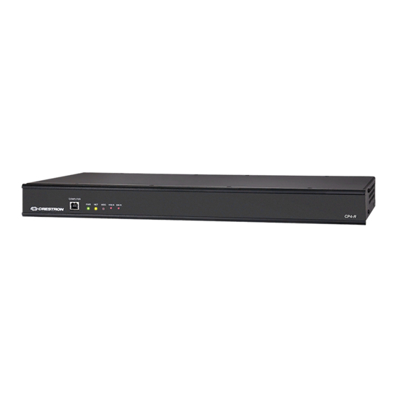
Physical Description The CP4 and CP4N provide the following connectors and indicators. CP4 and CP4N Front Panel CP4 and CP4N Rear Panel Connectors and Card Slots RELAY OUTPUT (2) 8-pin 3.5 mm detachable terminal blocks; 1–8 Comprises (8) normally open, isolated relays; Rated 1 A, 30 VAC/VDC; MOV arc suppression across contacts I/O 1–8 (1) 9-pin 3.5 mm detachable terminal block;... - Page 15 (1) 8-pin RJ-45 connector, female; SUBNET (CP4N Only) 100/1000Base-TX Ethernet port; Provides a dedicated local network for Crestron devices (1) 4-pin 3.5 mm detachable terminal block; Cresnet master port; Outputs power to Cresnet devices only if the included power pack is connected to the 24 VDC power input jack;...
-
Page 16: Specifications
Specifications Refer to the following sections for more information on the specifications for various CP4 and CP4N models. CP4 Specifications (on page 13) CP4N Specifications (on page 17) 12 • CP4 and CP4N Product Manual — Doc. 9214A... -
Page 17: Cp4 Specifications
CP4 Specifications Product specifications for the CP4 are provided below. Product Specifications Control Engine Crestron 4-Series™; real-time, preemptive multi-threaded/multitasking kernel; Transaction-Safe Extended FAT file system; supports up to 10 simultaneously running programs, native .AV Framework™ software program Communications Ethernet 100/1000 Mbps, auto-switching, auto-negotiating, auto-discovery, full/half... - Page 18 I/O 1–8 (1) 9-pin 3.5 mm detachable terminal block; Comprises (8) Versiport digital input/output or analog input ports (referenced to GND); Digital Input: Rated for 0–24 VDC, input impedance 20k Ω, logic threshold >3.125 V low/0 and <1.875 V high/1; Digital Output: 250 mA sink from maximum 24 VDC, catch diodes for use with real world loads;...
- Page 19 (1) Green LED, indicates operating power is supplied from the power pack or Cresnet power supply (1) Amber LED, indicates communication with Cresnet devices (1) Red LED, indicates control processor has generated an error message HW-R (1) Recessed push button, initiates hardware reset SW-R (1) Recessed push button, initiates software reset LAN (rear)
-
Page 20: Dimension Drawings
Dimension Drawings Add dimension drawings. 16 • CP4 and CP4N Product Manual — Doc. 9214A... -
Page 21: Cp4N Specifications
CP4N Specifications Product specifications for the CP4N are provided below. Product Specifications Control Engine Crestron 4-Series™; real-time, preemptive multi-threaded/multitasking kernel; Transaction-Safe Extended FAT file system; supports up to 10 simultaneously running programs, native .AV Framework™ software program Communications Ethernet 100/1000 Mbps, auto-switching, auto-negotiating, auto-discovery, full/half... - Page 22 CONTROL (1) 8-pin RJ-45 connector, female; SUBNET 100/1000Base-TX Ethernet port; Provides a dedicated local network for Crestron devices (1) 4-pin 3.5 mm detachable terminal block; Cresnet master port; Outputs power to Cresnet devices only if the included power pack is connected to the 24 VDC power input jack;...
- Page 23 COMPUTER (1) USB Type B connector, female; (front) USB 2.0 computer console port; For setup only Controls and Indicators (1) Green LED, indicates operating power is supplied from the power pack or Cresnet power supply (1) Amber LED, indicates communication with Cresnet devices (1) Red LED, indicates control processor has generated an error message HW-R (1) Recessed push button, initiates hardware reset...
-
Page 24: Dimension Drawings
Weight 3.12 lb (1.42 kg) Compliance Regulatory Model: M201903003; UL® Listed for US & Canada, CE, IC, FCC Part 15 Class B digital device Dimension Drawings Add dimension drawings. 20 • CP4 and CP4N Product Manual — Doc. 9214A... -
Page 25: Installation
Installation Use the following procedures to install the CP4 and CP4N control systems. Install the Control System The control system may be mounted into a rack or placed onto a flat surface. Rack Mounting The control system occupies 1U of rack space. 1. Use a #1 Phillips screwdriver to remove the six required screws from the control system assembly (shown in the illustration below). -
Page 26: Connect The Control System
Make all necessary connections to the control system as shown below. Observe the following when connecting the control system: Use Crestron power supplies for Crestron equipment. The control system may be powered with the included 24 VDC power supply or via Cresnet®... -
Page 27: Connect The Control Subnet (Cp4N Only)
IP address. 1. Connect the control system to the network. 2. Use the Device Discovery tool in Crestron Toolbox™ software to discover the control system and its IP address on the network. 3. Enter the control system IP address into a web browser. -
Page 28: Create An Admin Account
The first time the web configuration interface is accessed, a page is displayed asking the user to create an admin account. A similar message is displayed when connecting to the control system in Crestron Toolbox software if an admin account has not already been created. To create an admin account: 1. -
Page 29: Set The Time Zone
The control system provides native support for the .AV Framework™ software program. .AV Framework software is a web-based management solution that is used to deploy scalable Crestron® enterprise room solutions without requiring any programming. For more information on the capabilities supported by .AV Framework, visit www.crestron.com/avframework. - Page 30 After the control system reboots, click Open AV Framework Setup to launch the .AV Framework web configuration utility. For more information on configuring .AV Framework for the control system, refer to the .AV Framework Software for 4-Series Control Systems Operations Guide. 26 • CP4 and CP4N Product Manual —...
-
Page 31: Configuration
Connect to XiO Cloud Service (on page 65). To access the configuration interface: 1. Use the Device Discovery tool in Crestron Toolbox™ software to discover the control system and its IP address on the network. 2. Open a web browser. 3. Enter the control system IP address into the browser URL field. A login page is displayed. -
Page 32: Actions Menu
Security: Used to enable authentication and other security settings 802.1x Configuration: Used to configure IEEE 802.1x network authentication for control system security The Status tab is the default tab that is displayed, as shown in the previous image. Actions Menu The configuration interface provides an Actions drop-down menu on the top right of the page. The Actions menu may be accessed at any time. -
Page 33: Restore
Firmware Upgrade Dialog Box To upload a firmware PUF through the web configuration interface: NOTE: Visit the appropriate device product page or www.crestron.com/Support/Resource- Library to download the latest firmware PUF. 1. Click Browse, and then navigate to the firmware PUF on the host computer. -
Page 34: Manage Certificates
Manage Certificates Click Manage Certificates to manage any certificates that are installed on the control system. For more information on certificate management, refer to 802.1x Configuration (on page 62). Status Click the Status tab on the top left of the configuration interface to display selections for viewing the status of device, network, and USB, and .AV Framework™... -
Page 35: Network
Network Click Network to view the status of the network settings for the control system. Status Tab - Network The following Network information is displayed: Host Name: The control system hostname Domain Name: The control system domain name NIC 1 DNS Servers: The DNS (domain name server) addresses used to resolve the control system domain to an IP address Click the + (plus) icon next to Adapter 1 to display the following Ethernet settings: DHCP: Reports whether the IP address is dynamic (Yes) or static (No) -
Page 36: Program
Link Active: Reports the status of the Ethernet connection (A true message indicates that the Ethernet connection is active, while a false message indicates that the Ethernet connection is inactive.) MAC Address: The unique MAC (media access control) address for the Ethernet adapter Click the + (plus) icon next to Control Subnet to display the following Control Subnet settings (CP4N only): Auto Network Addressing: Reports whether the network address for the Control Subnet is... -
Page 37: Av Framework
Slave Mode Status: Indicates the connection status to a primary control system while in subordinate mode, shown only if subordinate mode is enabled If one or more programs have been loaded to the control system, expandable subsections are shown that correspond with the program slot. Expand the subsection for a given program slot to display details about the loaded program. -
Page 38: Settings
Settings Click the Settings tab on the top left of the configuration interface to display selections for configuring various control system settings. Settings Selections Each selection is described in the sections that follow. NOTE: If an invalid value is entered for a setting, the web interface will not allow changes to be saved until a valid value is entered. - Page 39 Settings Tab - System Setup Time/Date Click the + (plus) icon next to Time/Date to display the following time and date settings. Settings Tab - System Setup (Time/Date) Product Manual — Doc. 9214A CP4 and CP4N • 35...
- Page 40 Time Synchronization: Turn on the toggle to use time synchronization via NTP (Network Time Protocol). Synchronize Now: With Time Synchronization turned on, click Synchronize Now to synchronize the control system with the NTP server(s) entered in the NTP Time Servers table. NTP Time Servers: With Time Synchronization turned on, use the provided table to enter information regarding the NTP server(s) used to synchronize the date and time for the control system. ...
- Page 41 Network Click the + (plus) icon next to Network to display the following network settings. Settings Tab - System Setup (Network) Host Name: Enter the control system hostname. Domain: Enter the fully qualified domain name on the network. Primary Static DNS: Enter the primary DNS address. Secondary Static DNS: Enter the secondary DNS address.
- Page 42 Control Subnet (CP4N Only) Click the + (plus) icon next to Control Subnet to display the following Control Subnet settings. Settings Tab - System Setup (Control Subnet) NOTE: For more information on the Control Subnet, refer to the "Control Subnet" topic in 4-Series Control Systems Reference Guide.
- Page 43 Click Add to add a new port mapping rule into the table. Enter the following information for each entry: Enter the external port in the External Port text field. This is the port number that users outside the LAN must specify to connect to the service on the internal network.
- Page 44 Crestron Internet Protocol Click the + (plus) icon next to Crestron Internet Protocol to display the following Crestron Internet Protocol (CIP) port settings. Settings Tab - System Setup (Crestron Internet Protocol) Enter the Crestron Internet Protocol port used by the control system in the CIP Port text field.
- Page 45 Turn on the Web XPanel Enabled toggle to enable the Web XPanel functionality for the control system. Turn on the Secure Web XPanel Enabled toggle to enable a secure Web XPanel connection for the control system. If this toggle is turned on, the Web XPanel can only connect to the control system over encrypted TLS/SSL.
-
Page 46: Programs
Programs Click Programs to manage control system programs and to configure subordinate mode settings for the control system. Settings Tab - Programs Slave Mode NOTE: For more information on using subordinate mode for a 4-Series control system, refer to the "Master-Slave Mode" topic in the 4-Series Control Systems Reference Guide. - Page 47 If Slave Mode is turned on, enter the IP address or hostname of the primary control system in the Master IP/Hostname text field. If Slave Mode is turned on, enter the IP ID for the connection to the primary control system in the IP ID text field. Program Slot Management NOTE: For more information on managing programs on a 4-Series control system, refer to the "Program Management" topic in the...
- Page 48 Load a New Program To load a new program to the control system: 1. Click the Upload Program button in an available program slot. The Add Program dialog box is displayed. Add Program Dialog Box 2. If desired, fill the Do not copy IP Table check box to prevent the program IP table from being copied to the control system following the upload.
- Page 49 IP ID. Port #: Enter the port used for communication between device and control system. Room Id: Enter the Crestron Virtual Control (VC-4) room ID that is associated with the IP table entry. This setting is applicable only for VC-4 connections.
-
Page 50: Projects
Projects Click Projects to manage web and mobility projects for the control system. Settings Tab - Programs Each loaded project is represented in a table that provides the following information and controls: Projects: The project number on the control system Name: The name for the web or mobility project Mobility: Displays a green check icon if the project is a mobility project Web Project: Displays a green check icon if the project is a web project Actions: Click the trash can button... - Page 51 3. Click the Project File button. The File Upload dialog box is displayed. File Upload Dialog Box 4. Click Browse, and then navigate to the project file on the host computer. 5. Select the project file, and then click Open. 6. Click Load to load the project file to the control system. The upload progress is shown in the dialog box.
-
Page 52: Services
Turn on the Crestron Fusion Cloud toggle to allow a connection to a Crestron Fusion Cloud server. If Crestron Fusion Cloud is turned on, enter the URL used to connect the control system to the desired Crestron Fusion Cloud server in the Crestron Fusion Cloud URL text field. -
Page 53: Cloud Settings
Apple HomeKit NOTE: For more information on pairing the device with an Apple® HomeKit® system, refer to support.apple.com/en-us/HT204893. Turn on the Apple Home Kit toggle to enable the HomeKit feature on the control system. Cloud Settings Click Cloud Settings to enable or disable a connection between the control system and an XiO Cloud®... -
Page 54: Auto Update
Auto Update Click Auto Update to configure automatic firmware updates for the control system and connected devices. Settings Tab - Auto Update NOTE: For more information on configuring automatic updates for the control system, refer to the "Auto Update Mechanism" topic in the 4-Series Control Systems Reference Guide. - Page 55 Enter a password for accessing the auto update server in the Password text field. Crestron Devices The following settings can be configured for updating connected Crestron devices if Auto Update is turned on: Enter a username for pushing automatic updates to controlled Crestron devices in the Username text field.
-
Page 56: Av Framework
AV Framework Click AV Framework to configure the native .AV Framework software program running on the control system. Settings Tab - AV Framework NOTE: If an older version of the .AV Framework program is detected in the Program 01 slot (6.13 and prior), the program is loaded to the Program 00 slot but is not enabled within the control system. -
Page 57: Security
Security Click the Security tab on the top left of the configuration interface to display selections for configuring security and authentication settings for the control system. Security Tab Selections Expand the Security accordion to configure the following settings: NOTE: For more information about configuring authentication settings on a 4-Series control system, refer to the "Authentication" topic in the 4-Series Control Systems Reference Guide. -
Page 58: Current User
Control system users and groups can be viewed and modified within the table provided at the bottom of the accordion. Use the following settings to add, delete, and edit control system users and groups. Current User Click the Current User tab to view and edit information for the current control system user. Current User Tab The following settings are displayed for the current user: Name: The chosen username... -
Page 59: Users
Change Password Dialog Box Enter the existing password in the Current Password field. Then, enter a new password in the Password field, and reenter the password in the Confirm Password field. Click OK to save the new password, or click Cancel to cancel the change. Users Click the Users tab to view and edit information for the control system users. - Page 60 NOTE: A user must be added to an Active Directory group before the user may be selected as an active directory user. For more information, refer to Groups (on page 59). If the control system users span multiple pages, use the navigation arrows on the bottom of the page to move forward or backward through the pages, or select a page number to navigate to that page.
- Page 61 Update User Dialog Box The following Update User settings may be viewed or configured: Name: The chosen username Active Directory User: Turn on the toggle to use authentication via Active Directory for the selected user. Password: Enter a new password for the selected user. Confirm Password: Reenter the password provided in the Password field.
- Page 62 Create User Dialog Box Use the following settings to create a new user: Name: Enter a username. Active Directory User: Turn on the toggle to use authentication via Active Directory for the user. Password: Enter a password for the user. Confirm Password: Reenter the password provided in the Password field.
-
Page 63: Groups
Groups Click the Groups tab to view and edit settings for control system groups. Control system groups are used to group users by access level and Active Directory authentication settings. Groups Tab Enter text in to the Search Groups field to find and display groups that match the search term (s). - Page 64 Active Directory group in the Name field. If this information is being entered via console commands, omit domain\local from the command (for example, adddomaing -n:crestron -L:A instead of adddomaing - n:domain.local\crestron -L:A). Access Level: The access level of the group and its users...
- Page 65 Create Group Dialog Box Use the following settings to create a new group: Name: Enter a group name. Access Level: Select an access level for the group and its users from the drop-down menu. Active Directory Group: Turn on the toggle to use authentication via Active Directory for the group.
-
Page 66: 802.1X Configuration
802.1x Configuration Click the 802.1x Configuration tab on the top left of the configuration interface to display selections for configuring IEEE 802.1x network authentication for control system security. 802.1x Configuration Tab Selections Expand the 802.1x Configuration accordion to configure the following settings: NOTE: For more information about configuring 802.1x network authentication on a 4-Series control system, refer to the "802.1X" topic in the 4-Series Control Systems Reference... - Page 67 Authentication Method: Select an 802.1x authentication method (EAP-TLS Certificate or EAP MSCHAP V2- password) from the drop-down menu. Domain: If EAP MSCHAP V2- password is selected for Authentication Method, enter a domain name that is required for authentication. Username: If EAP MSCHAP V2- password is selected for Authentication Method, enter a username that is required for authentication.
- Page 68 Type a search term into the Search… text field to search for and display CAs that match the search term. The following information is provided for each type of CA: Name: The CA name Expiry Date: The date and time that the CA is set to expire If the CAs span multiple pages, use the navigation arrows on the bottom of the page to move forward or backward through the pages, or select a page number to navigate to that page.
-
Page 69: Connect To Xio Cloud Service
XiO Cloud® service allows supported devices across an enterprise to be managed and configured from one central and secure location in the cloud. Supported Crestron® devices are configured to connect to the service out of the box. Use of the service requires a registered XiO Cloud account. To register for an XiO Cloud account, refer to www.crestron.com/Support/Tools/Licensing-Registration/XiO-Cloud-Registration-... -
Page 70: Programming
Programming 4-Series control systems support an open development environment that enables programmers to use standard tools to create C# programs. Programmers can also use Crestron tools such as SIMPL, SIMPL# Pro, and VT Pro-e® software to create control system programs and projects. -
Page 71: Resources
Resources The following resources are provided for the CP4 and CP4N. NOTE: You may need to provide your Crestron.com web account credentials when prompted to access some of the following resources. Crestron Support and Training Crestron True Blue Support Crestron Resource Library Crestron Online Help (OLH) Crestron Training Institute (CTI) Portal... - Page 72 Product Manual — Doc. 9214A Crestron Electronics, Inc. 15 Volvo Drive, Rockleigh, NJ 07647 01/14/22 Tel: 888.CRESTRON Specifications subject to Fax: 201.767.7656 change without notice. www.crestron.com...
Need help?
Do you have a question about the 4 Series and is the answer not in the manual?
Questions and answers