Table of Contents
Advertisement
Quick Links
Advertisement
Table of Contents

Related Manuals for Stanton SCS.1m


Summary of Contents for Stanton SCS.1m
- Page 1 SCS.1m Mixer Control Surface/Audio Interface User Manual...
- Page 2 Please read the warranty. • The warranty will be void if any unauthorized service by the user is detected. • If service is required, please contact Stanton Tech at +1 954.316.1500 (Option 3) WARNINg To reduce the risk of electric shock, do not expose this apparatus to rain or moisture. Ensure that the apparatus is not exposed to splashing and that no objects filled with liquids, such as vases, are placed on the apparatus.
-
Page 3: Table Of Contents
Contents Contents 1. Introduction ……………………………………………………………………………………………………………………………………....1 1.1 Welcome to the SCS.1m ………………………………………………………………….…..…..........1 1.2 Overview ……………………………………………………………………………………………………………………………….……....2 1.3 Unpacking …………………………………………………………………………………………………………………......... 2 2. Connecting the SCS.1m ……………………………………………………………………………………………………………………....3 2.1 Connecting to Your Computer ……………………………………………………………………………………………….……..…….. 3 2.2 Connecting to Audio Components ……………………………………………………………………………………………..……..4 2.3 Connecting to the SCS.1d …………………………………………………………………………………………………………..…….. -
Page 4: Introduction
Finally, we would like to point out that the descriptions of specific functionality of the SCS.1m are generic. The SCS.1m is a MIDI controller combined with an audio interface. Although it looks like an audio mixer, it in fact is not. -
Page 5: Overview
• (1) SCS.1m User Manual In addition to the above items, remember that to take advantage of the SCS.1m full potential you will need the SCS.1d or a traditional turntable, a Mac or PC computer, a DJ application, and to install DaRouter software. So let’s get started! -
Page 6: Connecting The Scs.1M
Looking at the output voltage will tell you which is for which component, (e.g., 12V for the SCS.1m, and 24V for the SCS.1d). There is also a label on each of the power cords to specify which product they are to be used with. -
Page 7: Connecting To Audio Components
Connecting to Audio Components Connecting to Audio Components Figure 2.4... -
Page 8: Connecting To The Scs.1D
Figure 2.6 Likewise, if you’re connecting two SCS.1ds to a SCS.1m, then you would go from the free FireWire port on the first SCS.1d to a port on the second. Any other FireWire devices should go at the end of the chain and not before any of the SCS.1 controllers. -
Page 9: Scs.1M Description
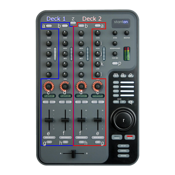
It’s important to understand that the SCS.1m is a traditional DJ mixer “analogy” in a control surface. This means that while the SCS.1m looks like a DJ mixer, at its core, it is really a control surface. As a control surface, the SCS.1m’s functionality is completely derived from the host application (software) that it is controlling. - Page 10 Top Panel Functional groups Top Panel Functional groups (continuation) Figure 3.1 Now, let’s take a closer look of each of the functional groups.
-
Page 11: Channel Strip
Channel Strip 3.1.1 Channel Strip The button at the top of the strip might be mapped to functionalities like deck or channel focus, a shift modifier, etc. Five rotary encoders in the top section of the channel strip can be mapped to traditional mixer functions like gain, EQ, and panning. -
Page 12: Crossfader Section
3.1.4 Master Section The Master Section controls various SCS.1m outputs. (Figure 3.5) The ZONE knob is meant to be mapped to an Aux out, like a booth monitor or effects send. This is a MIDI control and does not affect the Aux output on the rear panel of the mixer. -
Page 13: Browser Section
Browser Section 3.1.5 Browser Section This area of the SCS.1m would typically be mapped to browser-type functionality, whether that is scrolling through your library in Traktor, or selecting scenes in Ableton Live. (Figure 3.6) The three buttons at the top of the section can be used to select and activate banks or directory trees. -
Page 14: Front Panel
Front Panel In this panel, you will be able to connect your headphones. Stanton has included a headphone extender cable as the headphone jack is recessed into the panel to prevent accidentally damaging the headphone jack. Stanton has designed the headphone output to be extremely powerful and loud;... -
Page 15: Rear Panel
9. Footswitch Input: A footswitch may be connected for toggling of virtual decks or any other MIDI control in software. Important The SCS.1m is not an analog mixer, even though it looks like one. It is a MIDI Controller and an Audio Interface (soundcard). -
Page 16: Scs.1M Software Installation
In short, if you are a PC user, you will run one installer that will install the SCS.1m driver and DaRouter. If you are a Mac user, you do not need to install any driver. -
Page 17: Windows Xp
1. Double click the executable file (.exe). If the following Open File- Security Warning appears, click Run. (Figure 4.1) Figure 4.1 2. The Stanton SCS.1 DaRouter Setup Wizard will guide you through the installation process. Click Next. (Figure 4.2) Figure 4.2... - Page 18 DaRouter Installation - Windows XP 3. To install the software for the first time, choose the Standard option. To update your previously installed version, choose Custom. In this example, let’s choose Standard. (Figure 4.3) Figure 4.3 4. Read the License Agreement, select the “I accept the agreement” option, and then click Next. (Figure 4.4) Figure 4.4...
- Page 19 ON yet. When you are ready, click Next. (Figure 4.5) Figure 4.5 6. Please wait while Stanton 1394 ASIO Driver is being installed, and then turn your SCS.1 controllers ON and click OK. (Figure 4.6) Figure 4.6...
- Page 20 Stanton 1394 ASIO Driver Installation - Windows XP 7. We are almost ready to complete the Stanton 1394 ASIO Driver Setup installation. Click Next. (Figure 4.7) Figure 4.7 8. Stanton 1394 ASIO Driver has been installed. Click Finish to close this wizard. (Figure 4.8)
- Page 21 Bome’s Virtual MIDI Ports Installation - Windows XP 9. Now let’s install Bome’s Virtual MIDI ports. Read carefully the following instructions and click OK. (Figure 4.9) Figure 4.9 10. Select No, not this time and click Next. (Figure 4.10) Figure 4.10...
- Page 22 Bome’s Virtual MIDI Ports Installation - Windows XP 11. Select Install the software automatically and click Next. (Figure 4.11) Figure 4.11 12. Click Continue Anyway. (Figure 4.12) Figure 4.12...
- Page 23 Bome’s Virtual MIDI Ports Installation 13. Click Finish to complete the Bome’s Virtual MIDI Port device. (Figure 4.13) Figure 4.13...
- Page 24 Figure 4.14 You will see a new section called Stanton 1394 Audio Devices that includes the Stanton 1394 Virtual Device and a hardware specific driver for each controller you have connected. Check that the SCS.1m and SCS.1d devices are attached to your computer.
-
Page 25: Mac Os X
1. Connect SCS.1 controllers to the computer's FireWire port but have them powered OFF. Turn ON your SCS.1m controller. Open the Audio MIDI Setup applet to make sure it is recognized. The Audio MIDI Setup applet is located in Applications\Utilities. You should see the SCS.1m located in the Audio tab. (Figure 4.16) - Page 26 DaRouter Installation - Mac OS X To install DaRouter, please follow the next instructions 1. Double click the .dmg file to expand it. (Figure 4.17) Figure 4.17 2. Double click the DaRouter.pkg file to start the installer. (Figure 4.18) Figure 4.18...
- Page 27 DaRouter Installation - Mac OS X 3. Once the installer has started, click Continue. (Figure 4.19) Figure 4.19 4. Read the license agreement and click Continue. In the next dialog, click Agree. (Figure 4.20) Figure 4.20...
- Page 28 DaRouter Installation - Mac OS X 5. Next, you can set the default path of the program. Click Install unless you want to install DaRouter to a specific destination. (Figure 4.21) Figure 4.21 6. DaRouter will be installed. Once done, click Close. (Figure 4.22) Figure 4.22...
- Page 29 DaRouter Installation - Mac OS X 7. DaRouter will be installed into your Applications folder and the presets will be placed in your home directory. Plug in your SCS.1m, start DaRouter, and read the rest of this documentation. (Figure 4.23) Figure 4.23...
-
Page 30: Darouter
More importantly, presets can be created and edited freely with virtually no limit to what SCS.1m can do, thus opening up a whole element in control surface DJing. It is important to constantly check the Stanton website and forums for new presets. -
Page 31: Section A
The preset documentation includes all the setup instructions for using the preset with the application it was designed for. To fully take advantage of the SCS.1m capabilities it is strongly recommended to click the Preset Documentation button and read its content every time that you load a new preset. (Figure 5.2) 5.2.2... - Page 32 For example, if you click the SCS.1m Options button the SCS.1m Audio Control Panel will open so you will be able to Start and Stop the streaming process, access the Deferred Procedure Calls (DPC) Latency Checker (for more information please read the Appendix), and select the Sampling Rate, FireWire Latency, and ASIO Buffering settings.
-
Page 33: Section C
DaRouter - SCS.1d Options Now, if you click the SCS.1d Options button the SCS.1d Control Panel will open, so you will be able to change the Scratch Engage, the Scratch Release, and Pitch Bend Sensitivity values. (Figure 5.5) Scratch Engage Sensitivity – The SCS.1d uses an algorithm to detect scratching to accommodate MIDI scratching implementation in host applications such as Traktor. -
Page 34: Using Darouter
Loading a Preset Confirm that no preset is loaded and your SCS.1m is connected. At this point, you may select the preset you wish to use and then read its included documentation by clicking the “?” button. Also, remember to check the Stanton website for the... -
Page 35: Troubleshooting
You probably have the power supplies for each controller swapped. If you plug the wrong power cord into a unit, it won’t power up. The power cable for the SCS.1m supplies 12V, and the one for the SCS.1d supplies 24V. You can also tell which is which by the color-coding. -
Page 36: Specifications
Specifications Specifications Output Level Balanced +23 dBu into 100K Equalization (20 Hz-20 kHz) Less than +/- 0.4 dB Balanced THD+N (1 kHz) Less than 0.005% Balanced Output SNR (A-weighted) Greater than 108 dB Balanced Output crosstalk Less than -100 dB RCA Output level +17 dBu into 100K RCA THD+N (1 kHz) -
Page 37: Appendix
If you are having issues getting your computer to recognize the SCS.1m then it is suggested to start with the SidSpeed fix. If you are having issues with audio performance (drop outs) then it is first suggested to perform the following steps: •... - Page 38 Appendix - DPC (Windows XP-Vista) Figure A.1 The green Bar Graph shows the current latency value over time. Each bar represents the maximum DPC latency occurred within one second. Every second, bars are scrolled from right to left and a new bar is added at the right-hand side, (representing the most recent value).
- Page 39 Appendix - DPC (Windows XP-Vista) For example, a typical problem is shown in the next figure. Red bars indicate excessive DPC latency. (Figure A.2) Figure A.2 So let’s open Device Manager to find out the driver that causes the excessive DPC latencies. On your desktop, right click My Computer icon and click Properties.
- Page 40 Appendix - DPC (Windows XP-Vista) Figure A.3 Now, before you start finding out which device could be the cause of the excessive DPC latency, please follow these suggestions: You should not disable: • any device listed in Device Manager under System devices or Computer •...
- Page 41 Appendix - DPC (Windows XP-Vista) To disable a device, right-click on it (e.g. on the Ethernet adapter) and choose Disable. The disabled device will be marked with a red cross. (Figure A.4) Figure A.4 Now, check the DPC Latency Checker to see if the excessive latency values (red bars) disappeared. If yes, we have found the problem, if not, try the next device.
-
Page 42: Windows 1394A Bandwidth Limiting Issue (Windows Xp-Vista)
Appendix - Windows 1394a Bandwidth Limiting Issue (Windows XP-Vista) Windows 1394a Bandwidth Limiting Issue (Windows XP-Vista) First, let’s explain a little about what the SidSpeed Fix is. Basically, SidSpeed is a value in your windows registry that regulates the speed of your FireWire bus. It can have a value from 0-3 (0=S100 speed, 1=S200 speed, 2=S400 speed, and 3=800 speed). - Page 43 Appendix - Windows 1394a Bandwidth Limiting Issue (Windows XP-Vista) This will open your Registry Editor, which will look like this…(Figure A.7) Figure A.7 Now, before we go any further, we need to give you a warning and back some things up. The registry is a dangerous place to be playing around.
- Page 44 Appendix - Windows 1394a Bandwidth Limiting Issue (Windows XP-Vista) Now click File, and then click Export. A new window will pop up. (Figure A.9) Figure A.9 At the bottom of the new window, there is an area called Export Range. Make sure that Selected Branch is marked, and that the text in the field there says HKEY_LOCAL_MACHINE.
- Page 45 Appendix - Windows 1394a Bandwidth Limiting Issue (Windows XP-Vista) Then expand the SYSTEM branch. (Figure A.11) Figure A.11 Then expand CurrentControlSet. (Figure A.12) Figure A.12...
- Page 46 Appendix - Windows 1394a Bandwidth Limiting Issue (Windows XP-Vista) Now expand Enum. (Figure A.13) Figure A.13...
- Page 47 Appendix - Windows 1394a Bandwidth Limiting Issue (Windows XP-Vista) Then expand the PCI branch. (Figure A.14) Figure A.14 Now we need to find the specific key for your FireWire controller. As you can see, all the devices are named in a way that does not seem to make a whole lot of sense.
- Page 48 Appendix - Windows 1394a Bandwidth Limiting Issue (Windows XP-Vista) Leave the Regedit window open and go back to Start > Run. Type in devmgmt.msc and then press OK. (Figure A.15) Figure A.15 This will open your Device Manager. Look for your FireWire controller (commonly called IEEE 1394). One example is highlighted in Figure A.16.
- Page 49 Appendix - Windows 1394a Bandwidth Limiting Issue (Windows XP-Vista) Now click on the Details tab. (Figure A.17) Figure A.17 See this string of text? This is what we are going to look for in the PCI branch we have open in Regedit. Going back to Regedit, we can see that I got a little lucky and have it as the first key.
- Page 50 Appendix - Windows 1394a Bandwidth Limiting Issue (Windows XP-Vista) If you expand out the device subkey, you’ll find another subkey called Device Parameters. Click it to select it and look in the right pane. (Figure A.19) Figure A.19 In the example above, the SidSpeed key actually exists, but it is set to the incorrect speed. Double click on the SidSpeed value and a window will open.
- Page 51 If you encounter an error during any step of this process (especially Vista users and errors about not having proper rights to alter a registry value), please contact Stanton Technical support. If you made a mistake and need to restore your registry,...
-
Page 52: Firewire Chipsets
PC does not have FireWire capabilities, as some no-name or “OEM” FireWire cards will use chipsets of FireWire that have subpar performance and can affect stability or at worst the device will not work at all. Stanton recommends the Texas Instruments®... - Page 53 Warranty Service in the United States: Please contact Stanton Tech Support BEFORE sending your product. In some cases, our Tech Support team can resolve your problem immediately, avoiding down time due to shipping delays. However, if Tech Support determines that a repair is needed;...
- Page 54 Stanton dealer in the country where the purchaser is located or the country in which the merchandise was received. Any returns to a non-authorized dealer or to an authorized Stanton dealer not in the same country as the merchandise was intended to be sold or as set forth above will void this warranty.
- Page 55 Notes ....................................................................................................................................................................................................................................................................................................................................................................................................................................................................................................................................................................................................................................................................................................................................................................................................................................................................................................................................................................
- Page 56 SC System, DaRouter, SCS.1m, and SCS.1d are trademarks of the Stanton Group. All other trademarks are property of their respective owners, who are in no way affiliated with Stanton DJ or SC System products. All information included in the User Manual is subject to change without notice.
Need help?
Do you have a question about the SCS.1m and is the answer not in the manual?
Questions and answers