Advertisement
SERVICE MANUAL
Ver 1.0 2000. 03
SPECIFICATIONS
Frequency range:
Italy
Band
ICF-703
ICF-703L
FM
87.5 - 108.0 MHz
AM
526.5 - 1606.5 kHz
Other countries
Band
ICF-703
ICF-703L
FM
87.5 - 108.0 MHz
87.5 - 108.0 MHz
SW
—
AM (MW)
530 - 1605 kHz
530 - 1605 kHz
LW
—
153 - 255 kHz
Speaker
Approx. 10.2 cm (4
inches) dia. 8 ohms
1/8
Power output
430 mW (at 10 % harmonic distortion)
Output
v jack (ø 3.5 mm minijack)
Power requirements
With the supplied AC power cord:
220 - 230 V AC, 50 Hz
With four R6 (size AA) batteries: 6V DC
Dimensions
Approx. 265
137 69 mm (w/h/d)
(10
5
2
inches) incl. projecting parts
1/2
1/2
3/4
and control with carrying handle pushed in.
Mass
Approx. 1019 g (2 lb 4 oz) incl. batteries
Supplied accessory
AC power cord (1)
Design and specifications are subject to change without
notice.
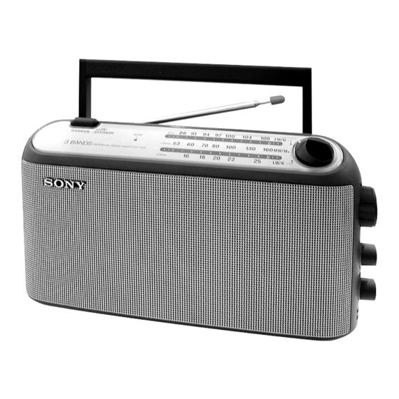
ICF-703/703L
(Photo: ICF-703L (BLACK))
—
—
—
FM/MW/LW 3 BAND RADIO
– 1 –
AEP Model
ICF-703/703L
UK Model
ICF-703L
FM/AM RADIO
ICF-703
ICF-703L
Advertisement
Table of Contents

Related Manuals for Sony ICF-703


Summary of Contents for Sony ICF-703
- Page 1 ICF-703/703L SERVICE MANUAL AEP Model ICF-703/703L Ver 1.0 2000. 03 UK Model ICF-703L (Photo: ICF-703L (BLACK)) SPECIFICATIONS Frequency range: Italy Band ICF-703 ICF-703L 87.5 - 108.0 MHz — 526.5 - 1606.5 kHz — Other countries Band ICF-703 ICF-703L 87.5 - 108.0 MHz 87.5 - 108.0 MHz...
-
Page 2: Safety-Related Component Warning
COMPONENTS IDENTIFIED BY MARK 0 OR DOTTED LINE WITH MARK 0 ON THE SCHEMATIC DIAGRAMS AND IN THE PARTS LIST ARE CRITICAL TO SAFE OPERATION. REPLACE THESE COMPONENTS WITH SONY PARTS WHOSE PART NUMBERS APPEAR AS SHOWN IN THIS MANUAL OR IN SUPPLEMENTS PUBLISHED BY SONY. -
Page 3: Section 1 General
Indicador de sintonia (TUNE) supplied) with correct polarity. Indicatore TUNE Close the lid. ICF-703 Battery life Using Sony LR6(size AA) alkaline batteries: Approx. 100 hours Using Sony R6 (size AA) batteries: Approx. 35 hours ICF-703S Replacing batteries When the sound becomes weak or distorted, replace all the batteries with new ones. -
Page 4: Section 2 Disassembly
SECTION 2 DISASSEMBLY Note : Follow the disassembly procedure in the numerical order given. 2-1. CABINET (REAR) 1 lid, battery case 4 BTP 3x16 3 BTP 3x16 2 BTP 3x16 5 cabinet (rear) 2-2. POWER BOARD 6 POWER board 1 BTP 3x10 4 Removal the solders. -
Page 5: Setting The Pointer
2-3. MAIN BOARD, LED BOARD 4 Removal the solder. 9 BTP 3x10 8 BTP 3x10 qa MAIN board 3 chassis 7 claws 6 LED board 5 BTP 2.6x5 1 knob (control) 2 knob (band) 2-4. SETTING THE POINTER • Setting the Pointer 1. -
Page 6: Section 3 Electrical Adjustments
ICF-703: AM/MW FREQUENCY COVERAGE ADJUSTMENT FM FREQUENCY COVERAGE ADJUSTMENT Adjust for a maximum reading on level meter 520 (516.5) kHz... - Page 7 • Repeat the procedures in each adjustment several times, and the ICF-703L: frequency coverage and tracking adjustments should be finally LW SECTION done by the trimmer capacitors. BAND switch : LW LW FREQUENCY COVERAGE ADJUSTMENT AM RF signal Adjust for a maximum reading on level meter Put the lead-wire generator antenna close to...
- Page 8 ICF-703/703L SECTION 4 DIAGRAMS 4-1. PRINTED WIRING BOARDS ANT1 TELESCOPIC ANTENNA DRY BATTERY SIZE " D " (IEC DESIGNATION R20) POWER BOARD MAIN BOARD 3PCS, 4.5V (703L) (703) TP10 TP11 TP12 TONE T401 POWER (703) TRANSFOMER (703L) C403 D401 C404...
- Page 9 ICF-703/703L 4-2. SCHEMATIC DIAGRAMS Note: • All capacitors are in µF unless otherwise noted. pF: µµF 50 WV or less are not indicated except for electrolytics and tantalums. • All resistors are in W or less unless otherwise specified. •...
-
Page 10: Section 5 Exploded View
SECTION 5 EXPLODED VIEW NOTE: • The mechanical parts with no reference • Color Indication of Appearance Parts • Abbreviation 5-2. CABINET (REAR) SECTION number in the exploded views are not supplied. Example : IT : Italian model • Items marked “*” are not stocked since KNOB, BALANCE (WHITE) ... -
Page 11: Section 6 Electrical Parts List
SECTION 6 MAIN ELECTRICAL PARTS LIST NOTE: • Due to standardization, replacements in • Items marked “*” are not stocked since The components identified by the parts list may be different from the they are seldom required for routine service. mark 0 or dotted line with mark parts specified in the diagrams or the Some delay should be anticipated... - Page 12 ICF-703/703L MAIN POWER Ref. No. Part No. Description Remark Ref. No. Part No. Description Remark 1-216-296-91 SHORT < CAPACITOR > 1-216-296-91 SHORT JC10 1-216-296-91 SHORT C401 1-164-004-11 CERAMIC CHIP 0.1uF JC11 1-216-296-91 SHORT 0 (703L) C402 1-126-927-11 ELECT 2200uF 20.00% 10V...
Need help?
Do you have a question about the ICF-703 and is the answer not in the manual?
Questions and answers