Advertisement
Quick Links
www.collegehillshonda.com
INSTALLATION
INSTRUCTIONS
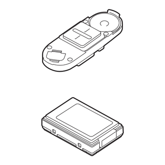
PARTS LIST
HFL Attachment Kit
P/N 08E02-SHJ-100B
HFL trim
HFL bracket
HFL harness
HFL subharness
2 Double-faced tapes
HFL retainer
Template
© 2008 American Honda Motor Co., Inc. - All Rights Reserved.
Accessory
Accessory HandsFreeLink
AII 38137-38714 (0801)
Application
2008 ODYSSEY
Fuse label
Fuse (2 A)
6 EPT sealers
8 Wire ties
4 Self-tapping screw, 3 x 10 mm
2 Washer screws, 4 x 12 mm
Self-tapping screw
Bush
Ground bolt
Rubber bumper
Publications No.
AII 38137-38714
Issue Date
JAN 2008
1 of 12
08E02-SHJ-1B00-91
Advertisement

Related Manuals for Honda 08E02-SHJ-100B


Summary of Contents for Honda 08E02-SHJ-100B
- Page 1 INSTALLATION INSTRUCTIONS PARTS LIST HFL Attachment Kit P/N 08E02-SHJ-100B HFL trim HFL bracket HFL harness HFL subharness 2 Double-faced tapes HFL retainer Template © 2008 American Honda Motor Co., Inc. - All Rights Reserved. Accessory Accessory HandsFreeLink Fuse label Fuse (2 A)
-
Page 2: Installation
HFL Blue Tooth Kit P/N 08E00-E10-100 Switch Control unit Accessory User's Information Manual TOOL AND SUPPLIES REQUIRED #2 Phillips screwdriver 10 mm Combination wrench 10 mm and 14 mm Socket Pushpin Ratchet 3 mm, 4.5 mm, 6 mm, 9 mm, and 10 mm Drill bit Eye protection (face shield, safety goggles, etc.) File Diagonal cutters... - Page 3 Disengage eight retaining tabs and remove left and right lens from the roof console. VEHICLE CONNECTORS SUNGLASS HOLDER (Open.) 2 BOLTS LEFT 4 RETAINING LENS TABS Open the sunglass holder. Remove four bolts and lower the roof console. Disconnect the two vehicle connectors and remove the roof console.
- Page 4 10. Remove the left front door sill trim (three clips). 3 CLIPS LEFT FRONT DOOR SILL TRIM 11. Pull away the weatherstrip from the left kick panel. Remove the left kick panel (three clips). WEATHERSTRIP 4 of 12 12. Attach the fuse label (2 A) to the fuse case of the HFL subharness.
- Page 5 NOTE: If another accessory is already plugged into the 6-pin connector, remove the dummy connector from the 6-pin connector taped to the HFL subharness. Plug the 6-pin connector from the other accessory harness into the 6-pin connector from the HFL subharness you just unplugged and plug the HFL subharness into the fuse box.
- Page 6 20. Secure the HFL subharness to the vehicle harness with a wire tie. VEHICLE PANEL VEHICLE HARNESS 21. Using isopropyl alcohol on a shop towel, clean the area where the EPT sealer will attach. Attach a EPT sealer to secure the HFL subharness to the vehicle panel.
- Page 7 27. Remove the console light from the roof console (four retaining tabs). 4 RETAINING TABS 28. Enlarge the hole on the roof console with 9 mm drill bit. ROOF CONSOLE DRILL BIT (9 mm) © 2008 American Honda Motor Co., Inc. - All Rights Reserved. 29.
- Page 8 34. Drill 4.5 mm holes at the two locations marked on the roof console in step 32. After drilling, remove any burrs. DRILL BIT (4.5 mm) ROOF CONSOLE 2 MARKS 35. Attach template B with masking tape on the roof console at the indicated position.
- Page 9 42. Using a utility knife, cut along the marking made on the roof console in step 37. After cutting, remove any burrs. ROOF CONSOLE Mark made in step 37. ROOF CONSOLE Cut out. 43. Remove the masking tape attached in step 29. 44.
- Page 10 48. Bend the switch terminal as shown. BACKSIDE OF THE SWITCH SPEAKER SWITCH TERMINAL SWITCH RUBBER BUMPER RETAINER 49. Insert the rubber bumper to the HFL retainer. 50. Assemble HFL retainer, switch, and HFL trim with four 3 x 10 mm self-tapping screws. 10 of 12 51.
- Page 11 55. Hold the roof console close to the roof console opening and connect the HFL harness 4-pin connector to the HFL subharness 4-pin connector. WIRE TIE GREEN CONNECTOR VEHICLE BRACKET SUBHARNESS 4-PIN Vehicle front CONNECTOR HFL HARNESS 4-PIN CONNECTOR ROOF CONSOLE 56.
- Page 12 60. Attach the fuse label to the No. 33 slot on the fuse box cover. FUSE LABEL (OPITION FUSE 2 A) FUSE BOX COVER 12 of 12 61. Check that all wire harnesses are routed properly and that all connectors are plugged in. 62.
Need help?
Do you have a question about the 08E02-SHJ-100B and is the answer not in the manual?
Questions and answers