Harman Kardon AVR154 Service Manual
5 x 30w 5.1 channel a/v receiver
Hide thumbs
Also See for AVR154:
- Owner's manual (60 pages) ,
- Brochure & specs (24 pages) ,
- Quick start manual (2 pages)
Table of Contents
Advertisement
harman/kardon
5 X 30W 5.1 CHANNEL A/V RECEIVER
ESD WARNING.....................................2
LEAKAGE TESTING...............................3
BASIC SPECIFICATIONS.......................4
PACKAGING........................................5
FRONT PANEL CONTROLS.....................6
REAR PANEL CONNECTIONS................8
REMOTE CONTROL FUNCTIONS..........10
CONNECTIONS/INSTALLATION.............13
OPERATION.......................................24
TROUBLESHOOTING GUIDE.................29
REMOTE & PROCESSOR RESETS..........30
Released 2008
Discontinued XXXX
AVR154
SERVICE MANUAL
CONTENTS
harman/kardon, Inc.
250 Crossways Park Dr.
Woodbury, New York 11797
DISASSEMBLY......................................31
UNIT EXPLODED VIEW..........................32
EXPLODED VIEW PARTS LIST...............33
AMP BIAS ADJUSTMENT......................34
BLOCK DIAGRAM................................35
PCB DRAWINGS.................................36
ELECTRICAL PARTS LIST.....................42
SEMICONDUCTOR PINOUTS................71
SCHEMATICS....................................132
WIRING DIAGRAM..............................140
Rev0 5/2008
Advertisement
Table of Contents

Subscribe to Our Youtube Channel
Related Manuals for Harman Kardon AVR154


Summary of Contents for Harman Kardon AVR154
-
Page 1: Table Of Contents
AVR154 5 X 30W 5.1 CHANNEL A/V RECEIVER SERVICE MANUAL CONTENTS ESD WARNING……………………………….2 DISASSEMBLY…...…………………………..31 LEAKAGE TESTING……………….…..…..3 UNIT EXPLODED VIEW…………..…….…..32 BASIC SPECIFICATIONS…………………..4 EXPLODED VIEW PARTS LIST……………33 PACKAGING…………………………….……5 AMP BIAS ADJUSTMENT……………….…34 FRONT PANEL CONTROLS………..…..…..6 BLOCK DIAGRAM…………………………..35 REAR PANEL CONNECTIONS………….…8 PCB DRAWINGS……………………………36 REMOTE CONTROL FUNCTIONS……….10... -
Page 2: Esd Warning
AVR154 Some semiconductor (solid state) devices can be damaged easily by static electricity. Such components commonly are called Electrostatically Sensitive (ES) Devices. Examples of typical ES devices are integrated circuits and some field effect transistors and semiconductor "chip" components. -
Page 3: Leakage Testing
AVR154 SAFETY PRECAUTIONS The following check should be performed for the continued protection of the customer and service technician. LEAKAGE CURRENT CHECK Measure leakage current to a known earth ground (water pipe, conduit, etc.) by connecting a leakage current tester... -
Page 4: Basic Specifications
All features and specifications are subject to change without notice. Distortion (TIM) Unmeasurable Harman Kardon and Logic 7 are trademarks of Harman International Industries, Incorporated, registered Slew Rate 40V/µsec in the United States and/or other countries. Designed to Entertain is a trademark of Harman International Industries, Incorporated. -
Page 5: Packaging
AVR154 1. Instruction manual ass'y - Accessories 2. Package Drawing CARD WARRANTY POLY BAG AM LOOP ANTENNA ASS'Y MANUAL ASS'Y SNOW PAD (L) SNOW PAD (R) FM 1 POLE ANT(UL) MANUAL INSTRUCTION BATTERY ASS'Y AVR154 REMOCON SHEET GUIDE STAPLE TRANSMITTER ASS'Y... -
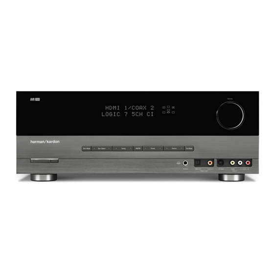
Page 6: Front Panel Controls
Check all speaker wires for a possible short. If none is found, bring After you have selected the desired surround the unit to an authorized Harman Kardon service center for inspection mode group, press this button to select a specific mode. - Page 7 AVR154 Message Display Remote Speaker/Channel IR Sensor Volume Input Indicators Headphone Digital Power Surround Tuning Preset Stations Video 3 Jack Audio Inputs Indicator Mode Analog Audio (Optical 3 and Inputs Main Power Standby/On Tuner Band Source Tuning Surround Video 3...
-
Page 8: Rear Panel Connections
AVR154 REAR-PANEL CONNECTIONS AM and FM Antenna Terminals: Coaxial Digital Audio Output: Connect the included AM and If a source is also a digital audio FM antennas to their respective terminals for radio reception. recorder, connect the coaxial digital audio output to the recorder’s coaxial digital input. - Page 9 AVR154 Video 2 Video 1 Video Monitor HDMI Tape FM Antenna Inputs Inputs Outputs Inputs (1, 2 and 3) Outputs Video 1 Component Component Tape DVD A/V HDMI Video Inputs Video Monitor AC Power AM Antenna Inputs Outputs Inputs...
-
Page 10: Remote Control Functions
Video 1: Controls VCRs, TiVo ® devices and DVRs, and the Harman Kardon DMC 1000 digital media center. Sleep Button: Press this button to activate the sleep timer, which Video 2: turns off the receiver after a programmed period of time of up to Controls cable and satellite television set-top boxes. - Page 11 AVR154 IR Transmitter Lens Power On Mute Program Indicator Power Off Input Selectors AVR Selector AM/FM Test Tone 6-Channel Input Selector Sleep Volume Controls DSP Surround TV/Video On-Screen Display Speaker Setup Channel Level Navigation Digital Input Delay Numeric Keys...
- Page 12 AVR154 REMOTE CONTROL FUNCTIONS Tuning Mode: Macros: This button toggles between manual (one frequency These buttons may be programmed to execute long step at a time) and automatic (seeks frequencies with acceptable signal command sequences with a single button press. They are useful for strength) tuning mode.
-
Page 13: Connections/Installation
AVR154 CONNECTIONS There are different types of audio and video connections used to Bare wire cables are installed as follows (see Figure 2): connect the receiver to the speakers and video display, and to connect 1. Unscrew the terminal cap until the pass-through hole in the collar the source devices to the receiver. -
Page 14: Audio Connections
AVR154 CONNECTIONS Audio Connections the source. These types of connections are usually used with DVD- Audio, SACD, Blu-ray Disc, HD-DVD and other multichannel players. There are two formats for audio connections: digital and analog. Digital See Figure 7. audio signals are required for listening to sources encoded with digital surround modes, such as Dolby Digital and DTS. - Page 15 AVR154 CONNECTIONS The AVR 154 will not convert analog video signals to the HDMI format, and the on-screen displays are not visible when using an HDMI source. Component Connect the composite or S-video monitor output (or both, depending video cable on which video connections your sources use) to your video display to view the on-screen menus.
- Page 16 AVR154 INSTALLATION You are now ready to connect your various components to your receiver. Step Three – Connect the Antennas Before beginning, turn off all components, including the AVR 154, and Connect the FM and AM antennas to their terminals. See Figure 18.
- Page 17 AVR154 INSTALLATION Video Connections: (choose only one, and make sure that type is available on your TV) • HDMI • S-video • Component video • Composite video AVR 154 NOTES: • Digital audio, HDMI and component video connections are not dedicated to any source input.
- Page 18 AVR remote to operate the player. Figure 21 – Connecting a Component-Video-Equipped Disc Player • Connect a Harman Kardon DMC 1000 digital media center to If the player is capable of playing multichannel discs, including DVD-Audio, any available HDMI Input for digital video and any available input...
- Page 19 AVR154 INSTALLATION • Connect the recorder’s optical digital audio output to the Optical 2 Connect a Cable TV, Satellite, HDTV or Other Set-Top Input on the AVR (if available). Box for Broadcast Television • Then go to “Composite/S-Video” below to make recordings, as the...
- Page 20 Harman Kardon Parts Dept. You may then connect it to any set of analog audio inputs. Video Components: Install video components, e.g., game consoles...
- Page 21 AVR154 INSTALLATION AVR 154 AVR 154 Figure 34 – Component Video Monitor Outputs Figure 32 – Connecting a Device to the Front-Panel Inputs Composite/S-Video: Important – do not skip this step, even if you have connected the AVR’s HDMI or Component Video Monitor Audio Components: Connect audio-only devices, such as CD players, Outputs to the display.
- Page 22 • Press DVD to operate a DVD player. Figure 36 – Remote Control Battery Compartment • Press VID1 to operate a VCR or PVR, or a Harman Kardon digital media center. When using the remote, remember to point the lens toward the front panel of the AVR 154.
- Page 23 45 for instructions on these advanced programming functions. NOTE: The AVR 154 remote is preprogrammed to operate the transport controls of Harman Kardon DVD players when the AVR or the Video 2 (cable/satellite) or Video 3 (TV) source is selected.
-
Page 24: Operation
AVR154 OPERATION Now that you have installed your system components and completed If you press the Sleep Button after the timer has been set, the remaining at least a basic configuration of your receiver, you are ready to begin time until turn-off will be displayed. -
Page 25: Source Selection
AVR154 OPERATION If you wish to return the tone controls to 0, or “flat” response, press the Source Selection ⁄ ¤ Buttons, until the TONE OUT message appears, which preserves Press the front-panel Source Select Button to scroll through the sources. - Page 26 AVR154 OPERATION The COMPONENT IN line of the Input Setup menu indicates which of c) Connect the player’s 6-channel analog audio outputs to the AVR’s the two component video inputs on the AVR 154 is assigned to each 6-Channel Inputs and assign the Component Video 1 Inputs to source.
-
Page 27: Aux Input
AUX Input Press the Tuning Mode Button (TUN-M on the remote) to switch Enjoy the full power and resolution of your Harman Kardon system, between Auto and Manual tuning modes. See Figure 60. When an FM including a variety of analog surround modes, while listening to content station has been tuned, pressing the Tuning Mode Button will switch stored on your portable device. - Page 28 AVR154 OPERATION Selecting a Surround Mode Surround mode selection can be as simple or sophisticated as your individual system and tastes. Feel free to experiment with the many available surround modes on the AVR 154, and you may find a few that become your favorites for certain sources or program types.
-
Page 29: Troubleshooting Guide
• Amplifier is in protection mode • Contact your local Harman Kardon service center due to internal problems No sound from surround or • Incorrect surround mode • Select a mode other than Stereo center speakers •... -
Page 30: Remote & Processor Resets
AVR154 Erase a macro as follows: 1. Simultaneously press and hold the Mute Button and the Macro Button containing the macro until the LED flashes. 2. Press the Surround Button to erase the macro. Resetting the Remote To reset the remote to its factory defaults, simultaneously press and hold any Input Selector and the “0”... -
Page 31: Disassembly
AVR154 DISASSEMBLY AVR154 1. Removing the Top Cabinet 3. Removing the Rear Panel Remove the Screws Remove the Screws 21 22 4. Removing the Main PCB Remove the Screws 2. Removing the Front Panel Remove the Screws... -
Page 32: Unit Exploded View
AVR154 AVR154 EXPLODED VIEW 40-4 40-1 40-3 40-5 40-6 38-1 38-2 40-2 DESCRIPTION PARTS NO. Q,ty Weright ORNAMENT,VOLUME CGU1A318Z CAP,VOLUME CGX1A338MBC63 HOLDER,VOLUME CMH1A214 INDICATOR,VOLUME CGL1A222 WINDOW ASS'Y CGUAVR154 WINDOW,FIP CGU2A399X BADGE,MODEL CGB1A191Z SHEET,VOLUME CMZ2A090 FILTER,FIP CMZ1A088Z BDAGE,HARMAN/KARDON CGB1A158Y PANEL,FRONT... -
Page 33: Exploded View Parts List
AVR154... -
Page 34: Amp Bias Adjustment
AVR154 CUP12026* (MAIN PCB) VR83 VR84 VR85 VR82 VR86 (AVR154, 155)),CN62(FR) -
Page 35: Block Diagram
AVR154 BLOCK DIAGRAM... -
Page 36: Pcb Drawings
AVR154... - Page 37 AVR154...
- Page 38 AVR154...
- Page 39 AVR154...
- Page 40 AVR154...
- Page 41 AVR154...
-
Page 42: Electrical Parts List
AVR154 AVR154 Electrical Parts List Ref. Designator Part Number Description FRONT PCB ASSY CUP12025 Capacitors C714 CCBS1H151KBT CAP , CERAMIC 150UF 50V K C716 CCEA1AH331T CAP , ELECT 330UF 10V C719 CCBS1H102KBT CAP , CERAMIC 1000PF 50V K C720... - Page 43 AVR154 Ref. Designator Part Number Description FRONT PCB ASSY CUP12025 D775 CVD1SS133MT DIODE 1SS133 D784 CVD1SS133MT DIODE 1SS133 D785 CVD1SS133MT DIODE 1SS133 Q701 HVTKRC107MT TRANSISTOR NPN KRC107M Q722 HVTKRA107MT TRANSISTOR PNP KRA107M Q724 HVTKRC107MT TRANSISTOR NPN KRC107M Q725 HVTKRC107MT...
- Page 44 AVR154 Ref. Designator Part Number Description FRONT PCB ASSY CUP12025 R764 CRD20TF5601T RES , CARBON 5.6K /1/5W/F R765 CRD20TF7501T RES , CARBON 7.5K /1/5W/F R781 CRD20TJ102T RES , CARBON 1K OHM 1/5W J R783 CRD20TJ102T RES , CARBON 1K OHM 1/5W J...
- Page 45 AVR154 Ref. Designator Part Number Description FRONT PCB ASSY CUP12025 S711 HST1A020ZT SW , TACT TACT SWITCH S712 HST1A020ZT SW , TACT TACT SWITCH S713 HST1A020ZT SW , TACT TACT SWITCH S714 HST1A020ZT SW , TACT TACT SWITCH S715...
- Page 46 AVR154 Ref. Designator Part Number Description MAIN PCB/HEATSINK (CUP12026) C571 CCBS1H681KBT CAP , CERAMIC 680PF 50V C572 CCBS1H681KBT CAP , CERAMIC 680PF 50V C573 CCBS1H681KBT CAP , CERAMIC 680PF 50V C574 CCBS1H681KBT CAP , CERAMIC 680PF 50V C575 CCBS1H681KBT...
- Page 47 AVR154 Ref. Designator Part Number Description MAIN PCB/HEATSINK (CUP12026) C904 KCKDKS472ME CAP , CERAMIC(X1/Y2/SC) 0.0047UF/2.5KV C906 CCEA1EH102E CAP , ELECT 1000UF 25V C909 CCET50VKL4682NK CAP , ELECT 6800UF/50V C915 CCET50VKL4682NK CAP , ELECT 6800UF/50V C916 CCET50VKL4682NK CAP , ELECT...
- Page 48 AVR154 Ref. Designator Part Number Description MAIN PCB/HEATSINK (CUP12026) Q558 HVTKTC3200GRT TRANSISTOR NPN KTC3200GR Q559 HVTKTC3200GRT KTC3200GR TRANSISTOR NPN Q560 HVTKTC3200GRT TRANSISTOR NPN KTC3200GR Q561 HVTKTC3200GRT KTC3200GR TRANSISTOR NPN Q562 HVTKTC3200GRT TRANSISTOR NPN KTC3200GR Q563 HVTKTC3200GRT TRANSISTOR NPN KTC3200GR...
- Page 49 AVR154 Ref. Designator Part Number Description MAIN PCB/HEATSINK (CUP12026) R509 CRD20TJ333T RES , CARBON 33K OHM 1/5W J R510 CRD20TJ333T RES , CARBON 33K OHM 1/5W J R511 CRD20TJ152T RES , CARBON 1.5K OHM 1/5W J R512 CRD20TJ152T RES , CARBON 1.5K OHM 1/5W J...
- Page 50 AVR154 Ref. Designator Part Number Description MAIN PCB/HEATSINK (CUP12026) R585 CRD20TJ561T RES , CARBON 560 OHM 1/5W J R586 CRD20TJ561T RES , CARBON 560 OHM 1/5W J R587 CRD20TJ561T RES , CARBON 560 OHM 1/5W J R588 CRD20TJ561T RES , CARBON...
- Page 51 AVR154 Ref. Designator Part Number Description MAIN PCB/HEATSINK (CUP12026) R681 CRD20TJ562T RES , CARBON 5.6K OHM 1/5W J R682 CRD20TJ562T RES , CARBON 5.6K OHM 1/5W J R683 CRD20TJ562T RES , CARBON 5.6K OHM 1/5W J R684 CRD20TJ562T RES , CARBON 5.6K OHM 1/5W J...
- Page 52 AVR154 Ref. Designator Part Number Description MAIN PCB/HEATSINK (CUP12026) R992 CRD20TJ562T RES , CARBON 5.6K OHM 1/5W J R998 CRD20TJ103T RES , CARBON 10K OHM 1/5W J R656 CRF5EKR27HX2K RES , CEMENT 0.27ohm X 2 R657 CRF5EKR27HX2K RES , CEMENT 0.27ohm X 2...
- Page 53 AVR154 Ref. Designator Part Number Description MAIN PCB/HEATSINK (CUP12026) TH91 KRTP42T7D330B THERMAL SENSOR , POSISTOR P42T7D330BW20 T902 CLT5I009ZU TRANS , SUB C515 TRANS CHD3A012R SCREW , SPECIAL SCREW PCB , POWER TRANS/DOWNLOAD/DIG IN/OUT CUP12101 Capacitors C104 CCBS1E103ZFT CAP , CERAMIC 0.01UF 25V...
- Page 54 AVR154 Ref. Designator Part Number Description PCB , POWER TRANS/DOWNLOAD/DIG IN/OUT CUP12101 D102 HVDMTZJ27BT DIODE , ZENER MTZJ27B 1/2W D104 CVD1N4003ST DIODE , RECT 1N4003 D105 CVD1N4003ST DIODE , RECT 1N4003 D108 CVD1N4003ST DIODE , RECT 1N4003 D109 CVDZJ8.2BT DIODE , ZENER ZJ8.2B 1/2W...
- Page 55 AVR154 Ref. Designator Part Number Description PCB , POWER TRANS/DOWNLOAD/DIG IN/OUT CUP12101 R913 CRD20TJ153T RES , CARBON 15K OHM 1/5W J R917 CRD20TJ153T RES , CARBON 15K OHM 1/5W J R918 CRD20TJ153T RES , CARBON 15K OHM 1/5W J...
- Page 56 AVR154 Ref. Designator Part Number Description PCB , INPUT CUP12028 C212 CCUS1H221JA CAP , CHIP 220PF 50V J C213 CCUS1H221JA CAP , CHIP 220PF 50V J C214 CCUS1H221JA CAP , CHIP 220PF 50V J C215 CCUS1H221JA CAP , CHIP...
- Page 57 AVR154 Ref. Designator Part Number Description PCB , INPUT CUP12028 C383 CCUS1H223KC CAP , CHIP 0.022UF 50V K C384 CCUS1H223KC CAP , CHIP 0.022UF 50V K C385 CCUS1H223KC CAP , CHIP 0.022UF 50V K C386 CCUS1H223KC CAP , CHIP 0.022UF 50V K...
- Page 58 AVR154 Ref. Designator Part Number Description PCB , INPUT CUP12028 C765 CCUS1H104KC CAP , CHIP 0.1UF 50V K C768 CCUS1H104KC CAP , CHIP 0.1UF 50V K C769 CCUS1H104KC CAP , CHIP 0.1UF 50V K C770 CCUS1H104KC CAP , CHIP 0.1UF 50V K...
- Page 59 AVR154 Ref. Designator Part Number Description PCB , INPUT CUP12028 C616 CCEA1CH101T CAP , ELECT 100UF 16V C618 CCEA1CH101T CAP , ELECT 100UF 16V C620 CCEA1CH101T CAP , ELECT 100UF 16V C622 CCEA1CH101T CAP , ELECT 100UF 16V C624...
- Page 60 AVR154 Ref. Designator Part Number Description PCB , INPUT CUP12028 Q729 HVTKRC107S TRANSISTOR , CHIP NPN KRC107S Q730 HVTKRC107S TRANSISTOR , CHIP NPN KRC107S D221 CVD1N4003ST DIODE , RECT 1N4003 D222 CVD1N4003ST DIODE , RECT 1N4003 D703 CVD1N4003ST DIODE , RECT...
- Page 61 AVR154 Ref. Designator Part Number Description PCB , INPUT CUP12028 R219 CRJ10DJ101T RES , CHIP 100 OHM R220 CRJ10DJ101T RES , CHIP 100 OHM R221 CRJ10DJ101T RES , CHIP 100 OHM R222 CRJ10DJ101T RES , CHIP 100 OHM R223...
- Page 62 AVR154 Ref. Designator Part Number Description PCB , INPUT CUP12028 R306 CRJ10DJ332T RES , CHIP 3.3K OHM R307 CRJ10DJ332T RES , CHIP 3.3K OHM R308 CRJ10DJ332T RES , CHIP 3.3K OHM R309 CRJ10DJ332T RES , CHIP 3.3K OHM R310...
- Page 63 AVR154 Ref. Designator Part Number Description PCB , INPUT CUP12028 R717 CRJ10DJ3R3T RES , CHIP 3.3K OHM R718 CRJ10DJ123T RES , CHIP 3.3K OHM R719 CRJ10DJ473T RES , CHIP 47K OHM R720 CRJ10DJ473T RES , CHIP 47K OHM R721...
- Page 64 AVR154 Ref. Designator Part Number Description PCB , INPUT CUP12028 R792 CRJ10DJ103T RES , CHIP 10K OHM R794 CRJ10DJ102T RES , CHIP 1K OHM R795 CRJ10DJ102T RES , CHIP 1K OHM R796 CRJ10DJ102T RES , CHIP 1K OHM Miscellaneous...
- Page 65 AVR154 Ref. Designator Part Number Description PCB , VIDEO CUP12030 C474 CCEA1CH101T CAP , ELECT 100UF 16V C481 CCBS1H101KBT CAP , CERAMIC(100PF/50V) 100PF 50V C483 CCBS1H101KBT CAP , CERAMIC(100PF/50V) 100PF 50V C491 CCBS1H101KBT CAP , CERAMIC(100PF/50V) 100PF 50V C492...
- Page 66 AVR154 Ref. Designator Part Number Description PCB , VIDEO CUP12030 C708 CCEA1HHR47T CAP , ELECT 0.47UF 50V C711 CCEA1AH471T CAP , ELECT 470UF 10V C717 CCBS1H220JCT CAP , CERAMIC(22PF/50V) 22PF 50V C721 CCBS1H560JT CAP , CERAMIC(56PF/50V) 56PF 10V C722...
- Page 67 AVR154 Ref. Designator Part Number Description PCB , VIDEO CUP12030 R411 CRD20TJ750T RES , CARBON 75 OHM 1/5W J R412 CRD20TJ750T RES , CARBON 75 OHM 1/5W J R413 CRD20TJ750T RES , CARBON 75 OHM 1/5W J R421 CRD20TJ750T...
- Page 68 AVR154 Ref. Designator Part Number Description PCB , VIDEO CUP12030 R605 CRD20TJ620T RES , CARBON 1/5W 62 OHM R611 CRD20TJ750T RES , CARBON 75 OHM 1/5W J R613 CRD20TJ750T RES , CARBON 75 OHM 1/5W J R615 CRD20TJ750T RES , CARBON...
- Page 69 AVR154 Ref. Designator Part Number Description HDMI PCB (CUP12109) C903 CCUS1H104KC CAP , CHIP 0.1UF 50V K C904 CCUS1H104KC CAP , CHIP 0.1UF 50V K C905 CCUS1H104KC CAP , CHIP 0.1UF 50V K C906 CCUS1H104KC CAP , CHIP 0.1UF 50V K...
- Page 70 AVR154 Ref. Designator Part Number Description HDMI PCB (CUP12109) R941 CRJ10DJ221T RES , CHIP 220 OHM R963 CRJ10DJ473T RES , CHIP 47K OHM R964 CRJ10DJ101T RES , CHIP 100 OHM Miscellaneous CN45 CJP07GA193ZY WAFER , CARD CABLE SMD WAFER...
-
Page 71: Semiconductor Pinouts
AVR154 AK4589 2/8-Channel Audio CODEC with DIR PVSS PVDD X'tal Clock Oscillato r 8 to 3 Recovery Clock MCKO1 Generator Input MCKO2 Selector LRCK2 DAIF A udio BICK2 Decode r SDTO2 DAUX2 A VDD A VSS DVDD Error &... - Page 72 AVR154 ASAHI KASEI [AK4589] -10 ∼ +70°C AK4589VQ 80pin LQFP(0.5mm pitch) AKD4589 TEST1 INT1 BOUT TVDD DVDD AVSS DVSS AVDD VREFH XT I VCOM (Top View) TEST3 MCKO2 MCKO1 ROUT1+ COUT ROUT1- UOUT LOUT1+ VOUT LOUT1- SDTO2 ROUT2+ BICK2...
- Page 73 AVR154 ASAHI KASEI [AK4589] AK4588 Functions AK4588 AK4589 DAC S/(N+D) 90dB 94dB DAC S/N 106dB 114dB Typ ±2.7Vpp DAC Output voltage Typ 3.0Vpp DAC AOUT AOUT=0.6xVREFH AOUT=0.54xVREFH Load Resistance 5k ohm 2k ohm ±1.0 Frequency Response 80kHz +0/-0.6 #35, #37, #39,#41,#43,#45,#47,#49 #35 - #50 Min=4.5V, Max=5.5V...
- Page 74 AVR154 ASAHI KASEI [AK4589] Pin Name Function INT1 Interrupt 1 Pin Block-Start Output Pin for Receiver Input BOUT “H” during first 40 flames. TVDD Output Buffer Power Supply Pin, 2.7V∼5.25V DVDD Digital Power Supply Pin, 4.75V∼5.25V DVSS Digital Ground Pin...
- Page 75 AVR154 ASAHI KASEI [AK4589] Pin Name Function Power-Down Mode Pin When “L”, the AK4589 is powered-down, all digital output pins go “L”, all registers are reset. When CAD1/0 pins are changed, the AK4589 should be reset by PDN pin.
- Page 76 AVR154 ASAHI KASEI [AK4589] Pin Name Function AVDD Analog Power Supply Pin, 4.75V∼5.25V Analog Ground Pin, 0V AVSS Receiver Channel 0 Pin (Internal biased pin. Internally biased at PVDD/2) No Connect pin No internal bonding. This pin should be connected to PVSS.
- Page 77 AVR154 ASAHI KASEI [AK4589] Classification Pin Name Setting Analog RX0-7, LOUT1-4, ROUT1-4, LIN, RIN These pins should be open. INT0-1, BOUT, XTO, MCKO1-2, COUT, UOUT, These pins should be open. VOUT, SDTO1-2, CDTO, DZF1-2, TX1-0 Digital These pins should be connected to DVSS.
- Page 78 AVR154 Video Switch · 75 driver · Y/C mix MM1501 MITSUMI Video Switch · 75 driver · Y/C mix Monolithic IC MM1501 Series Outline This IC extends the series of ICs for video/audio signal switching, with a 2-input 1-output single video switch, video signal/chroma signal 75 driver, and Y/C mixing circuit in one small package (SOT-26).
- Page 79 AVR154 Video Switch · 75 driver · Y/C mix MM1501 MITSUMI Block Diagram MM1501 MM1502 MM1503 MM1504 MM1505 MM1506...
- Page 80 AVR154 Video Switch · 75 driver · Y/C mix MM1501 MITSUMI MM1507 MM1508 MM1509 MM1510 MM1511 MM1512...
- Page 81 AVR154 HCF4053B TRIPLE 2-CHANNEL ANALOG MULTIPLEXER/DEMULTIPLEXER LOW "ON" RESISTANCE : 125 (Typ.) OVER 15V p.p SIGNAL-INPUT RANGE FOR = 15V HIGH "OFF" RESISTANCE : CHANNEL LEAKAGE 100pA (Typ.) at V = 18V BINARY ADDRESS DECODING ON CHIP HIGH DEGREE OF LINEARITY : < 0.5% DISTORTION TYP.
- Page 82 AVR154 HCF4053B INPUT EQUIVALENT CIRCUIT PIN DESCRIPTION PIN No SYMBOL NAME AND FUNCTION 11, 10, 9 A, B, C Binary Control Inputs Inhibit Inputs 12, 13, 2, 1, ax,ay,bx,by,cx,cy Input/ IN/OUT 5, 3 Output OUT/IN ax or ay OUT/IN...
- Page 83 AVR154...
- Page 84 AVR154...
- Page 85 AVR154...
- Page 86 AVR154...
- Page 87 AVR154...
- Page 88 AVR154...
- Page 89 AVR154...
- Page 90 AVR154...
- Page 91 AVR154...
- Page 92 AVR154...
- Page 93 AVR154...
- Page 94 AVR154...
- Page 95 AVR154...
- Page 96 AVR154...
- Page 97 AVR154...
- Page 98 AVR154...
- Page 99 AVR154...
- Page 100 AVR154...
- Page 101 AVR154...
- Page 102 AVR154 E S I E S I Excel Semiconductor inc. ES29LV320E 32Mbit(4M x 8/2M x 16) CMOS 3.0 Volt-only, Boot Sector Flash Memory GENERAL FEATURES • Minimum 100,000 program/erase cycles per sector • 20 Year data retention at 125 •...
- Page 103 AVR154 E S I E S I Excel Semiconductor inc. GENERAL PRODUCT DESCRIPTION Extra Security Sector of 256 bytes The ES29LV320 is a 32 megabit, 3.0 volt-only flash memory device, organized as 4M x 8 bits (Byte In the device, an extra security sector of 256 bytes is mode) or 2M x 16 bits (Word mode) which is config- provided to customers.
- Page 104 AVR154 E S I E S I Excel Semiconductor inc. PRODUCT SELECTOR GUIDE Family Part Number ES29LV320E Voltage Range 2.7V ~ 3.6 V Speed Option Max Access Time (ns) CE# Access (ns) OE# Access (ns) FUNCTION BLOCK DIAGRAM RY/BY#...
- Page 105 AVR154 E S I E S I Excel Semiconductor inc. PIN DESCRIPTION Description A0-A20 21 Addresses DQ0-DQ14 15 Data Inputs/Outputs DQ15 (Data Input/Output, Word Mode) DQ15/A-1 A-1 (LSB Address Input, Byte Mode) Chip Enable Output Enable Write Enable WP#/ACC...
-
Page 106: Connection Diagram
AVR154 E S I E S I Excel Semiconductor inc. CONNECTION DIAGRAM BYTE# DQ15/A-1 48-Pin Standard TSOP DQ14 DQ13 DQ12 RESET# ES29LV320E DQ11 WP#/ACC RY/BY# DQ10 48-Ball FBGA 6 x 8 mm) (Top View, Balls Facing Down) DQ15/ BYTE#... - Page 107 AVR154 ESMT M12L16161A SDRAM 512K x 16Bit x 2Banks Synchronous DRAM FEATURES GENERAL DESCRIPTION The M12L16161A is 16,777,216 bits synchronous high JEDEC standard 3.3V power supply data rate Dynamic RAM organized as 2 x 524,288 words by LVTTL compatible with multiplexed address 16 bits, fabricated with high performance CMOS technology.
- Page 108 AVR154 ESMT M12L16161A FUNCTIONAL BLOCK DIAGRAM Bank Select Data Input Register LDQM 512K x 16 512K x 16 Column Decoder Latency & Burst Length LCKE Programming Register LRAS LCBR LDQM LCAS LWCBR Timing Register L(U)DQM PIN FUNCTION DESCRIPTION Name Input Function Active on the positive going edge to sample all inputs.
- Page 109 AVR154...
- Page 110 AVR154...
- Page 111 AVR154...
- Page 112 AVR154...
- Page 113 AVR154 M24C64 M24C32 64Kbit and 32Kbit Serial I²C Bus EEPROM FEATURES SUMMARY Figure 1. Packages Two-Wire I C Serial Interface Supports 400kHz Protocol Single Supply Voltage: – 4.5 to 5.5V for M24Cxx – 2.5 to 5.5V for M24Cxx-W –...
- Page 114 AVR154 M24C64, M24C32 SUMMARY DESCRIPTION Table 2. Signal Names These I C-compatible electrically erasable pro- grammable memory (EEPROM) devices are orga- E0, E1, E2 Chip Enable nized as 8192 x 8 bits (M24C64) and 4096 x 8 bits (M24C32).
- Page 115 AVR154...
- Page 116 AVR154...
- Page 117 AVR154...
- Page 118 AVR154...
- Page 119 AVR154...
- Page 120 AVR154...
- Page 121 AVR154 NJM2595 5-INPUT 3-OUTPUT VIDEO SWITCH GENERAL DESCRIPTION PACKAGE OUTLINE The NJM2595 is a 5-input 3-output video switch. Its switches select one from five signals received from VTR,TV,DVD, TV-GAME and others. The NJM2595 is designed for audio items, such as AV amplifier and others.
- Page 122 AVR154 NJM2595 EQUIVALENT CIRCUIT PIN No. PIN NAME INSIDE EQUIVALENT CIRCUIT VOLTAGE Vin1 Vin2 Vin3 Vin4 Vin5 Vout1 Vout2 Vout3 2.1k Vout...
- Page 123 AVR154 NJM2595 EQUIVALENT CIRCUIT PIN No. PIN NAME INSIDE EQUIVALENT CIRCUIT VOLTAGE TEST CIRCUIT Vout2.2 Vout2.1 Vout3.2 Vout3.1 75 Ω 75 Ω 75 Ω 75 Ω 0.1µF Vin1 Vin2 75 Ω 75 Ω 100µF 10µF 10µF 1 10µF 10µF 10µF...
- Page 124 AVR154...
- Page 125 AVR154...
- Page 126 AVR154 LOW VOLTAGE DETECTOR R 5VT SERIES R 5VT PIN CONFIGURATION TO-92 • SOT-89 SOT-23-5 • • (mark side) (mark side) (mark side) PIN DESCRIPTION TO-92 SOT-89 SOT-23-5 • • • Pin No. Symbol Pin No. Symbol Pin No.
- Page 127 AVR154 74ACT04 HEX INVERTER HIGH SPEED: t = 5.0ns (TYP.) at V = 5V LOW POWER DISSIPATION: = 2 A(MAX.) at T =25°C COMPATIBLE WITH TTL OUTPUTS = 2V (MIN.), V = 0.8V (MAX.) 50 TRANSMISSION LINE DRIVING CAPABILITY...
- Page 128 AVR154 74ACT04 INPUT AND OUTPUT EQUIVALENT CIRCUIT PIN DESCRIPTION PIN No SYMBOL NAME AND FUNCTION 1, 3, 5, 9, 11, 1A to 6A Data Inputs 2, 4, 6, 8, 10, 1Y to 6Y Data Outputs Ground (0V) Positive Supply Voltage...
- Page 129 AVR154 SEMICONDUCTOR KIA278R05PI~KIA278R15PI TECHNICAL DATA BIPOLAR LINEAR INTEGRATED CIRCUIT 4 TERMINAL 2A OUTPUT LOW DROP VOLTAGE REGULATOR DIM MILLIMETERS 10.00 0.20 The KIA278R Series are Low Drop Voltage Regulator 15.00 0.20 2.70 0.20 suitable for various electronic equipments. 0.60 0.10 It provides constant voltage power source with TO-220 4 terminal Φ3.20 0.20...
-
Page 130: Technical Data
AVR154 KIA1117S/F00~ SEMICONDUCTOR KIA1117S/F50 TECHNICAL DATA BIPOLAR LINEAR INTEGRATED CIRCUIT LOW DROP FIXED AND ADJUSTABLE POSITIVE VOLTAGE REGULATOR The KIA1117S/F is a Low Drop Voltage Regulator able to provide up to 1A of output current, available even in adjustable version (Vref=1.25V) - Page 131 AVR154 TRANSISTOR, REGULATOR IC BLOCK DIAGRAM TO-92L TO-92M TO-92 TO-220 1. Emitter 1. Emitter 1. Emitter 1. GND 2. Collector 2. Collector 2. Collector 2. INPUT 3. Base 3. Base 3. Base 3. OUTPUT 1 23 1 2 3...
-
Page 132: Schematics
AVR154... - Page 133 AVR154...
- Page 134 AVR154...
- Page 135 AVR154...
- Page 136 AVR154...
- Page 137 AVR154...
- Page 138 AVR154...
- Page 139 CUP12026Z NOTE HIGHLIGHTED DIFFERENCES FOR MODEL AVR154,155 ONLY FAN USING FAN_H DC PROTECTOR SR-CH VCC1 VCC1 R634 R631 JK91 JW96_1 C-CH 2SD2389P:AVR154 SIG30 SIG30 2SB1559P:AVR154 2SD2390:AVR155/254/255 OVER 2SB1560:AVR155/254/255 OVER CENT CENTER 2SD2560:AVR354/355 SIG06 2SB1647:AVR354/355 SIG06 A1268GR A1360Y Q660 Q657 C574...
-
Page 140: Wiring Diagram
AVR154 WIRING.sch-1 - Wed Apr 23 10:30:18 2008 harman/kardon AVR154...
Need help?
Do you have a question about the AVR154 and is the answer not in the manual?
Questions and answers