Table of Contents
Advertisement
Quick Links
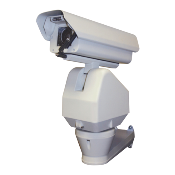
GV-SCS530 Users Manual
INTEGRATED PTZ POSITIONING
SYSTEM, 36X OPTICAL ZOOM, WDR,
D/N, INDOOR OUTDOOR CAMERA
before installing and using the camera, please read these instructions
thoroughly and retain them for later reference.
GVI Security
2801 Trade Center Dr., Suite 120 • Carrollton, TX 75007 • Toll Free: 888-595-2288 • www.gviss.com
Advertisement
Table of Contents

Related Manuals for GVI Security GV-SCS530


Summary of Contents for GVI Security GV-SCS530
- Page 1 GV-SCS530 Users Manual INTEGRATED PTZ POSITIONING SYSTEM, 36X OPTICAL ZOOM, WDR, D/N, INDOOR OUTDOOR CAMERA before installing and using the camera, please read these instructions thoroughly and retain them for later reference. GVI Security 2801 Trade Center Dr., Suite 120 • Carrollton, TX 75007 • Toll Free: 888-595-2288 • www.gviss.com...
- Page 2 SUMMARY The “Smart Camera System” GV-SCS530 is a high-performance, integrated positioning sys- tem featuring a 530TV Lines resolution, 36x optical zoom camera, lens and complete PTZ unit. Made from die-cast aluminum construction, with an IP66 rated weather-resistant design. The GV-SCS530 has a built-in heater, wiper, window defroster, sun-shield, anti-fogging, dust-proof and frost protection function.
-
Page 3: Notes For Attention
I. NoTES FoR ATTENTIoN 1. Read the manual carefully before installing the product. 2. Power Supply: 220V/110V/24V, refer to the sticker on the product. 3. Avoid incorrect shipping methods such as overstacking or strong vibration during the course of transportation, storage and installation, as the product could be damaged. 4. -
Page 4: Introduction Of Functions
II. INTRodUcTIoN oF FUNcTIoNS 1. Unlimited rotation 360° horizontally and from +33° to -80° vertically. 2. The horizontal speed is 0 - 40°/sec while the vertical speed is 0 - 20°/sec (wind speed less than 50 miles/hour). 3. At the preset position, the horizontal speed is 0 - 100°/sec while the vertical speed is 0 - 40°/ sec (wind speed less than 50 miles/hour). - Page 5 Table 1 Table of Addresses in dIp Switch Status of dIp Switch dress dIp-1 dIp-2 dIp-3 dIp-4 dIp-5 dIp-6 dIp-7 dIp-8 dIp-9 dIp-10 of pT 1023 Examples...
- Page 6 Table 2 Table of protocols in dIp Switch Selection of communication protocols common Baud Rates Type of pro- tocols dIp-1 dIp-2 dIp-3 dIp-4 dIp-5 dIp-6 SAMSUNG NEoN Santachi pElco-d pElco-p/4800 pElco-p/9600 pANASoNIc longcomity HUNdA600 lIlIN VIcoN MolYNx kAlATEl Reserved AlEc Ultrak Some protocols and their common baud rates in DIP switch are as follows:...
- Page 7 Table 3 Table of Baud Rates Setup of Baud Rates Baud Rates of Communication DIP-1 DIP-2 DIP-3 DIP-4 DIP-5 DIP-6 2400 bps 4800 bps 9600 bps 19200 bps View inward from the small hole on the bottom shown as in Figure 3.2.1, you can find a 4-bit DIP whose No.1 is the switch of the terminal resistor 120Ω, shown as in Figure 3.2.2.
- Page 8 It is recommended to mount the system with M8 screw. Step 1: There is a mobile plate on the underside of the support bracket. The plate can be opened when the screws on the front are removed. Lead the wires of the system into the bracket for connection.
- Page 9 Step 3: Fix the mounting plate with the pan/tilt on the ground. Take care that wires are put into the groove under the mounting plate to prevent the wires from being compressed. It is shown as Figure 3.5.3 Figure 3.5.3 6.
-
Page 10: Description Of Menu Functions
Green White Blue Alarm Input 1 Yellow Alarm Input 1 Green, Blue Alarm Common Terminal The alarm input should be switch signal otherwise internal circuit shall be damaged. The alarm shall be linked with the presser point, which should be set in the menu. In case two channels have alarm signals simultaneously, the pan/tilt shall response upon two channels one by one with the time interval of 2 seconds. - Page 11 2.2 dISplAY SETUp Id dISplAY: When this option is set at ON, the monitor shall display the address of the camera such as “CAM 001”. Id poS: To set up the display location of the address, which can be displayed at TOP-L (top left), TOP-R (top right), BOTT-R (bottom right) and BOTT-L (bottom left).
- Page 12 pRoGRAM AUTo pAN START poS: to set the start point of the Au- toPan. After entering, move the PT by the joystick. Push CLOSE button to save the current position and return. AUTo pAN ENd poS: to set the end point of the Auto- Pan.
-
Page 13: Special Operation
The top line and the bottom line display prompt message, and the middle area displays infor- mation of each locus, one line shows data of two points. Move the cursor by PAN LEFT/RIGHT and modify data by TILT UP/DOWN. Press the button down for 1 second to accelerate. Press CLOSE button to exit the edit state and store modification. -
Page 14: Specifications
SpEcIFIcATIoNS Model GV-ScS530 Image sensor 1/4” EX view HAD CCD Number of total pixels Approx. 380,000 pixels Lens 36x optical zoom,f=3.4 mm(wide)to 122.4 mm (tele), F1.6 to F4.5 Digital zoom 12x (432x with optical zoom) Angle of view (H) 57.8° (wide end) to 1.7° (tele end) - Page 15 NoTES...
- Page 16 GVI Security 2801 Trade Center Dr., Suite 120 • Carrollton, TX 75007 • Toll Free: 888-595-2288 • www.gviss.com v.11.06.08...
Need help?
Do you have a question about the GV-SCS530 and is the answer not in the manual?
Questions and answers