Table of Contents
Advertisement
Installation and Operation Manual
Eight Channel WEB and Voice Dial-Up Remote Control System
WVRC-8 Network Agent Version 3.01 and PIC firmware Version 1.38 or above. PCB Rev F and above.
CAUTION!
The following information pertains to the above version(s) of
firmware. If your unit is not loaded with this version of firmware,
please contact Broadcast Tools for an upgrade.
Due to the dynamic nature of product design, the information contained in this
document is subject to change without notice. Broadcast Tools, Inc., assumes no
responsibility for errors and/or omissions contained in this document. Revisions
of this information or new editions may be issued to incorporate such changes.
Broadcast Tools® is a registered trademark of Broadcast Tools, Inc.
Copyright, 1989 - 2011 by Broadcast Tools, Inc. All rights reserved.
No part of this document may be reproduced or distributed without permission.
Visit www.broadcasttools.com for important product update information.
WVRC-8
Manual Update: 07/13/2011
®
Advertisement
Table of Contents

Related Manuals for Broadcast Tools WVRC-8


Summary of Contents for Broadcast Tools WVRC-8
- Page 1 Installation and Operation Manual WVRC-8 Eight Channel WEB and Voice Dial-Up Remote Control System WVRC-8 Network Agent Version 3.01 and PIC firmware Version 1.38 or above. PCB Rev F and above. Manual Update: 07/13/2011 CAUTION! The following information pertains to the above version(s) of firmware.
-
Page 2: Table Of Contents
WVRC-8 Installation and Operation Manual Table of Contents Section Title Page # Introduction............. 4 Safety Information . - Page 3 WVRC-8 Installation and Operation Manual Table of Contents – cont’d Configure DIP Switch Settings ........22 Dial-up Operation .
-
Page 4: Introduction
Contact with high voltages can cause serious injury or death. The maximum recommended voltage for the WVRC-8 is 30V. Switching of high voltages should only be done external from the WVRC-8 and in a man- ner that isolates the voltages from accidental contact with humans. -
Page 5: Product Overview
The WVRC-8 is supplied with spoken words and phases in English, while the user is free to record words and phases in their language. In addition, the WVRC-8 may be pro- grammed for dial-up operation via HyperTerminal, while the Java applet programming can be performed using your favorite web browser. -
Page 6: Inspection
A UPS helps mini- mize the risk to the WVRC-8 and has the added benefit that it will then be able to notify you of the power outage by email, phone or pager depending on your system configuration. -
Page 7: Installation
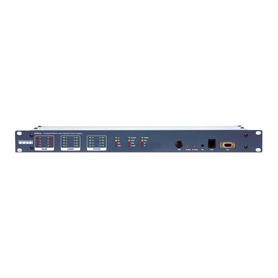
WVRC-8 Installation and Operation Manual Installation Front panel indicators, controls and connectors Name Type Description K1 - K8 Raise Illuminates when corresponding raise relays are acti- vated. K1 - K8 Lower Illuminates when corresponding lower relays are activated. ST1 - ST8 Illuminates when corresponding status inputs are activated. - Page 8 WVRC-8 Installation and Operation Manual Name Type Description SS Mon Control Sets the silence sensor audio sent to the phone line, when enabled. SS Sense Control Sets the audio trip point of the silence sensor. Microphone Peep hole Used to monitor site audio when enabled.
- Page 9 WVRC-8 Installation and Operation Manual Name Type Description ST1A - 8A Connector Status opto-isolators. When configured for DRY (fac- tory default) this terminal is ground. When configured for WET (floating), this terminal is the anode via a 2.2K ohm current limiting resistor. (BOTTOM)
-
Page 10: Connecting To Other Equipment
Permanent damage may occur to the WVRC-8 and/or external equipment if a high voltage metering source is con- nected to the WVRC-8! Failure to observe this warning may also cause injury to the installer or other personnel. -
Page 11: Raise/Lower Relays
KxR and KxR (where x is the channel number) for raise relays five through eight. Raise relays are on the TOP, while the lower relays are on the BOT- TOM. If mechanical relays are required, we suggest the Broadcast Tools LR-5- POLE mechanical latching relay. Alarm Relay The SPST normally open dry contact alarm relay is labeled “ALM”... -
Page 12: Telco Caller Audio Output
(WAN/LAN) port. POWER connector (12VAC) Connect the supplied 12VAC power supply cord in to the WVRC-8’s power jack labeled “12VAC 1 AMP”, then plug the transformer in to a source of 120vac 60Hz. Verify that the front panel green power led is illuminated. -
Page 13: Dial-Up Programming
WVRC-8 Installation and Operation Manual Dial-Up Programming Follow the steps below to configure the WVRC-8 for dial-up operation. Installing factory defaults. Remove power from the unit. Hold down the “PGM” button down while reinstalling the power plug. The “PGM” button must be held down for a few seconds after the power is restored. -
Page 14: Telnet Dialup Setup
(If the PC isn’t equipped with a serial (com) port, contact your local PC store or Broadcast Tools for a USB to RS-232 serial adapter) and connect the other end to the front or rear panel “PGM” DB-9 female serial connector. -
Page 15: Dial Out List
Status input 1 has a 1 programmed in to it. When status input 1 changes state, Visit our web site for the WVRC-8 will dial the number stored in dial out number location 11, which is referred product updates and to as dial out number 1. -
Page 16: Settings
The “Access Code” may be changed from the default code of 123, allowing a user all control functions. “Lap” defines the number of times the WVRC-8 will go through all of the numbers in the call-out list when calling out an alarm if it does not receive an acknowledgement. -
Page 17: Monitor Access Code
To force the WVRC-8 to dial a pager number, enter a “9” in the dial-list. That will cause the WVRC-8 to first dial the number in the page list, and then it will generate two digits to Identify the source of the alarm: 11à18 for analog (metering) inputs one through 8, 19... -
Page 18: Analog (Metering) Setup
WVRC-8 Installation and Operation Manual Analog (metering) Setup When “5” is selected from the PGM Menu, the analog (metering) calibration and alarm selections are displayed. Select “1” to calibrate any of the analog (metering) inputs for the desired value. Selecting a “1” will produce the following prompt “Select Ch 1-8 followed by the desired 4 digit value”. - Page 19 WVRC-8 Installation and Operation Manual Example: To enter low and high alarm set points of 30F and 95F, enter 0030/0095. To enter low and high alarm set points of 10C and 40C enter 1010/1040. Do not enter the “/”, it will be entered automatically.
-
Page 20: Recording Voice Prompts
WVRC-8 Installation and Operation Manual Recording Voice Messages The following steps are required to record voice messages into the WVRC-8. If the time allotted for the message you are recording elapses before the “PGM” button is pressed, it will turn off automatically. - Page 21 WVRC-8 Installation and Operation Manual Message Address Seconds Greeting Raise Lower Access Accepted Silence Alarm Power Fail Alarm High Status Input 1 Status Input 2 Status Input 3 Status Input 4 Status Input 5 Status Input 6 Status Input 7...
-
Page 22: "Configure" Dip Switch Settings
WVRC-8 Installation and Operation Manual Message Address Seconds Relay 5 Relay 6 Relay 7 Relay 8 Temperature Degrees Celsius Degrees Fahrenheit Minus Enabled Disabled Point Temperature Alarm “CONFIGURE” DIP Switch settings: The “UP” position is OFF DIP 1 - Feature creep. -
Page 23: Dial-Up Operation
WVRC-8 Installation and Operation Manual Dial Up Operation When the WVRC-8 is called, it will answer on the number of rings programmed. When it answers, enter the security code, which in this example is the default 123. The access LED will turn on once a valid security code is entered and the “Access Accepted”... - Page 24 WVRC-8 Installation and Operation Manual The status alarms can be controlled by entering 97 followed by the status number 1 through 8 and 1 for enable, 0 of disable or 9 for poll. The analog (metering) alarms can be controlled by entering 98 followed by the analog number 1 through 8, and 1 for enable, 0 for disable or 9 for poll.
-
Page 25: Web And Dial-Up Notice
WVRC-8 Installation and Operation Manual Web and/or Dial-up Notice The WVRC-8 can be used for dial-up only, web only or a combination of both. It is sug- gested that the user configure for both the dial-up and WEB operation. Some features such as the scheduler and logger will require the user to configure the web portion of the WVRC-8 even if web access isn’t being used. - Page 26 GRAY Xover CAT 5 cable and set your PC’s IP for 192.168.1.60 3 - Connect the supplied 12 VAC @ 1amp power supply to the WVRC-8’s power jack labeled 12VAC/1 Amp. Verify that the front panel power LED and left “LINK” LED above the “NETWORK”...
- Page 27 4 - Start the “Device Installer” software. a - Click on “SEARCH” b - When the WVRC-8 is found, click on the listed device. If more than one WVRC-8 is found, refer to the MAC address label attached to the WVRC-8 RJ-45 case and click on the desired WVRC-8, which should be highlighted.
-
Page 28: Firmware
Login failure count exceeds threshold Serial communication failure count exceeds threshold The WVRC-8 firmware supports an HTTP (web) interface on TCP port 80. The default page (index.html) contains a Java applet used to monitor and control the WVRC-8. Main Screen The main screen displays information identifying the site, gauges and LED’s representing... -
Page 29: Login Dialog
Displays the Status/Relay Setup dialog described below. Virtual Setup Displays the Virtual Setup dialog described below. Silence Alarms Sends the silence(clear)alarms command to the WVRC-8. Show Log Displays the event log as a text file in the browser. (IP/log.txt) Be sure to allow pop-ups. -
Page 30: User Setup Dialog
WVRC-8 Installation and Operation Manual User Setup Dialog The User Setup dialog is used to assign passwords and privilege levels for up to eight users. Privilege levels allow the following activities: None - Monitor analog (metering), status, and virtual inputs... -
Page 31: System Setup Dialog
WVRC-8 Installation and Operation Manual System Setup Dialog The Unit Setup dialog allows the user to set up the following operating characteristics of the WVRC-8 firmware and applet. Site ID Changes the site ID displayed on the main page. Station Call Letters Changes the station call letters displayed on the main page. -
Page 32: Network Setup Dialog
SMTP Port Outbound e-mail port, usually 25 but may be redefined by server administrator. Return Address Return e-mail address for alerts sent from the WVRC-8. Host ID Optional, in the form: host. domain. Recipient Addresses E-mail addresses (four) of alert recipients. -
Page 33: Schedule Setup Dialog
WVRC-8 Installation and Operation Manual Schedule Setup Dialog Raise, lower relays and alarm enable/disable can be activated on a scheduled basis. Up to 100 scheduled events can be defined. These can be one-time or repeating events. The Schedule Setup Dialog displays a list of scheduled events and allows the user to edit the schedule event’s details, described under Schedule Detail Dialog below. - Page 34 WVRC-8 Installation and Operation Manual The Schedule Detail Dialog is used to set up a single schedule event. An event specifies an action (raise or lower), a relay or alarm muting/unmuting, and a time when the action occurs. The scheduler supports both day-of-month and day-of-week schedules. Wildcards can be specified in any of the date/time fields to create a repeating event.
- Page 35 WVRC-8 Installation and Operation Manual Month Select the month when the event should occur, or ALL if the event should occur during every month. Day of Month Select the calendar day when the event should occur, or ALL if the event should occur every calendar day.
-
Page 36: Analog (Metering) Setup Dialog
WVRC-8 Installation and Operation Manual Analog (metering) Setup Dialog Analog (metering) Changes the label associated with any of the analog channels. Units Changes the units label associated with any of the analog (meter- ing) channels. Current Value Sets the analog scaling factor by associating the current A/D value with the user-supplied value. -
Page 37: Status/Relay Setup Dialog
WVRC-8 Installation and Operation Manual Status/Relay Setup Dialog Raise Relay Label Changes the label associated with any of the raise relays Lower Relay Label Changes the label associated with any of the lower relays Status Indicator Label Changes the label associated with any of the status items ON Alert Enables alerts when this status item changes from OFF to ON. -
Page 38: Virtual Channel Setup Dialog
WVRC-8 Installation and Operation Manual Virtual Channel Setup Dialog The WVRC-8 lets you define up to four “virtual” channels. These are similar to analog channels, but their values are derived from the product of two real analog channels and a constant. -
Page 39: Specifications
WVRC-8 Installation and Operation Manual Specifications Ethernet Interface: RJ-45, 10Base-T or 100Base-TX, auto sensing with Link & activity indicator - Full/half duplex. Control Logic: Microprocessor with non-volatile memory. Temperature Sensor: Sensor with 25-foot cable and 3.5mm T/R/S plug. -40°F to +190°F (-40°C to +85°C) -
Page 40: Declaration Of Conformity
WVRC-8 Installation and Operation Manual Declaration of Conformity The XPORT Device contained in the WVRC-8 conforms to the following stan- dards: (according to ISO/IEC Guide 22 and EN 45014) Manufacturer’s Name & Address: WVRC-8: Broadcast Tools, Inc. 131 State Street, Sedro Woolley, WA 98284-... -
Page 41: Warranty
If Broadcast Tools is notified, in writing, of a failure of any item manufactured by Broadcast Tools to conform to the foregoing Limited Warranty within one (1) year following the date of the Buyer’s acquisition of the item, and if the item is returned to Broadcast Tools in accordance with Broadcast Tools’... - Page 42 WVRC-8 Installation and Operation Manual APPENDIX e-mail: voice: fax: support@broadcasttools.com 360.854.9559 866.783.1742...
Need help?
Do you have a question about the WVRC-8 and is the answer not in the manual?
Questions and answers