Advertisement
®
Installation and Operation Manual
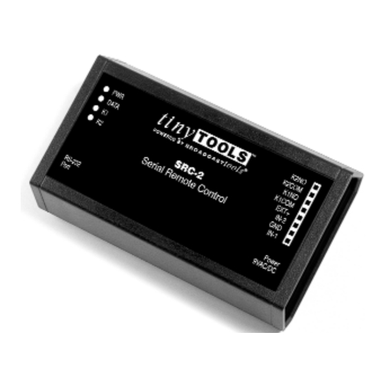
SRC-2
Serial Remote Control
Firmware Version 1.06
Manual update 7/13/2005
Due to the dynamic nature of product design, the information contained in this
document is subject to change without notice. Broadcast Tools, Inc., assumes no
responsibility for errors and/or omissions contained in this document. Revisions
of this information or new editions may be issued to incorporate such changes.
Broadcast Tools® is a registered trademark of Broadcast Tools, Inc.
Copyright, 1989 - 2005 by Broadcast Tools, Inc. All rights reserved.
No part of this document may be reproduced or distributed without permission.
Visit www.broadcasttools.com for important product update information.
Advertisement
Table of Contents

Subscribe to Our Youtube Channel
Related Manuals for Broadcast Tools SRC-2


Summary of Contents for Broadcast Tools SRC-2
- Page 1 Manual update 7/13/2005 Due to the dynamic nature of product design, the information contained in this document is subject to change without notice. Broadcast Tools, Inc., assumes no responsibility for errors and/or omissions contained in this document. Revisions of this information or new editions may be issued to incorporate such changes.
- Page 2 The tiny TOOLS, SRC-2 interfaces two optically isolated inputs and two SPST Broadcast Tools® relays to a RS-232 port. The SRC-2 can notify a users PC software program Products, as with any that any of two optically isolated inputs have been opened or closed and allows electronic device, can the users software to control two SPST, 1-amp relays.
- Page 3 Rack mounting: The SRC-2 may be rack mounted using the optional RA-1, 1-RU To make jumper or rack shelf. Apply a short strip of user-supplied Velcro to the bottom of the SRC-2 Dipswitch changes, all and attach the other mating strip to the surface of the RA-1.
- Page 4 8,N,1, while character echo must be turned on. Next, connect the supplied straight- through serial cable from the female DB-9 connector on the SRC-2 to the COM port on the PC or other serial device. To enter program mode, enter a “P” on the key- board.
- Page 5 SRC-2 Installation and Operation Manual Dipswitch 3 ON, (Dipswitch 4 OFF) = Pair mode, inputs from one SRC-2X will map directly to the outputs of another SRC-2X when connected together via the RS- 232 port. NOTE: When in pair mode, as soon as a communication failure is detect- ed, all relays will be turned off.
- Page 6 SRC-2 Installation and Operation Manual Specifications Inputs 2 - Optically isolated inputs. Internally powered or externally powered 5 to 24vdc. Relays 2 - SPST, 30Vdc/1 amp. Logic Flash Microprocessor with non-volatile memory RS-232 RS-232, 8N1. 300, 1200,4800, 9600. Handshaking disabled.
- Page 7 If Broadcast Tools is notified, in writing, of a failure of any item manufactured by Broadcast Tools to conform to the foregoing Limited Warranty within one (1) year following the date of the Buyer’s acquisition of the item, and if the item is returned in to Broadcast Tools in accordance with Broadcast Tools’...
Need help?
Do you have a question about the SRC-2 and is the answer not in the manual?
Questions and answers