Table of Contents
Advertisement
Quick Links
®
P R O B L E M S O LV E D
Installation and Operation Manual
®
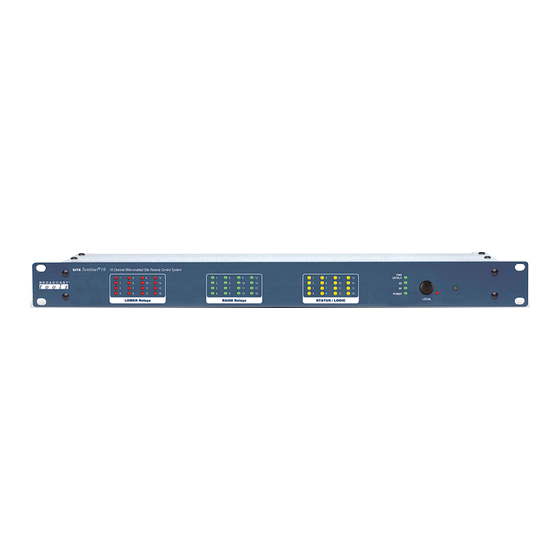
Site Sentinel
16
Web Enabled Sixteen Channel Site Remote Control System
Manual updated: 3/26/2024
For firmware versions equal to or greater than
PCB Rev D and lower: SS16X_V2.14 / SS16W_V1.40 / SS16P_V1.13
PCB Rev F and higher: SS16X_V2.23 / SS16W_V1.40 / SS16P_V1.20
If you need a firmware upgrade, contact Broadcast Tools®
No part of this document may be reproduced or distributed without permission.
ALL SPECIFICATIONS AND FEATURES FOR THIS PRODUCT ARE SUBJECT TO
CHANGE WITHOUT NOTICE
NOTE: We recommend the use of Chrome, Firefox or Safari as your browser.
Due to the dynamic nature of product design, the information contained in this
document is subject to change without notice. Broadcast Tools, Inc., assumes no
responsibility for errors and/or omissions contained in this document. Revisions
of this information or new editions may be issued to incorporate such changes.
Broadcast Tools® is a registered trademark of Broadcast Tools, Inc.
All Sentinel® labeled products are registered trademarks of Broadcast Tools, Inc.
Copyright® 1989 - 2024 by Broadcast Tools, Inc. All rights reserved.
No part of this document may be reproduced or distributed without permission.
Broadcast Tools is a Veteran Owned Business
Visit www.broadcasttools.com for important product update information.
Advertisement
Table of Contents

Subscribe to Our Youtube Channel
Related Manuals for Broadcast Tools Site Sentinel 16


Summary of Contents for Broadcast Tools Site Sentinel 16
- Page 1 NOTE: We recommend the use of Chrome, Firefox or Safari as your browser. Due to the dynamic nature of product design, the information contained in this document is subject to change without notice. Broadcast Tools, Inc., assumes no responsibility for errors and/or omissions contained in this document. Revisions of this information or new editions may be issued to incorporate such changes.
-
Page 2: Table Of Contents
® Site Sentinel 16 Installation and Operation Manual Table of Contents Section Title Page # Introduction............. 3 Who to Contact for Help . -
Page 3: Introduction
16 Installation and Operation Manual INTRODUCTION NOTE: Thank you for your purchase of Broadcast Tools® Site Sentinel® 16 Web Based Sixteen Channel Site Remote Control System (referred to as the Site Sentinel® 16 This manual should be throughout this manual). We’re confident that this product will give you many years read thoroughly before of dependable service. -
Page 4: Safety Information
Site Sentinel® 16. Broadcast Tools® Products, as with any electronic device, can fail without warn- ing. Do not use this product in applications where a life-threatening condition could result due to failure. -
Page 5: Product Overview
® Site Sentinel 16 Installation and Operation Manual Product Overview The Site Sentinel® 16 is a robust, full-featured, web-enabled sixteen channel remote control featuring a desktop/mobile browser compatible web interface (HTML5.) The system is equipped with 16 - 12-bit resolution, zero to 10 vdc metering channels; four virtual metering channels;... -
Page 6: Inspection
® Site Sentinel 16 Installation and Operation Manual Inspection CAUTION! Please examine your Site Sentinel® 16 carefully for any damage that may have been sustained during shipping. If any is noted, please notify the shipper immediately and Installation of Site retain the packaging for inspection by the shipper. - Page 7 ® Site Sentinel 16 Installation and Operation Manual Front panel indicators and controls (cont) Name Type Description PWR CNTR LED Illuminated when the relay is activated. Illuminated when adequate audio is applied to the SS Input(s), OFF when the level is too low and flashing if in an SS alarm condition, if enabled.
-
Page 8: Rear Panel Connections
® Site Sentinel 16 Installation and Operation Manual Rear panel connections (cont). Name Type Description PCNC Connector Power controller normally closed relay contact (Bottom). PCJP Connector Power controller internal function jumper (Bottom). MTR 1-16 Connector Metering (analog) inputs one through sixteen (Top). MGND Connector Metering (analog) ground reference... -
Page 9: Connecting Your Site Sentinel® 16 To External Equipment
® Site Sentinel 16 Installation and Operation Manual Connecting your Site Sentinel® 16 to external equipment. Chassis Ground (Chs Gnd) screws Either 6-32 screws MUST be connected to the station/site ground system for the proper operation of this equipment. Power Failure Input Connect a user supplied 5 to 12 volts DC only power source (center positive) to the power failure input labeled PF. -
Page 10: Metering (Analog) Inputs
® Site Sentinel 16 Installation and Operation Manual Metering (analog) Inputs CAUTION! Metering (analog) input samples may be elevated several hundred volts above ground on some external equipment. Permanent damage may occur to the Site Sentinel® 16 and/or external equipment if a high voltage metering source is connected to the Site Sentinel®... -
Page 11: Status/Logic Inputs
2200 ohms = Internal resistor For example: To connect a 48 VDC signal voltage to an input on Site Sentinel 16 in “wet” config- uration the completed equation for the external resistor value would be: R = ((48-1.2)/0.009)-2200 = 3000 ohms To calculate the power dissipated by the external resistor, the equation would be: P = I x I x R, so the resistor must be at least .009 x .009 x 2200 = 0.243 Watts,... -
Page 12: Raise And Lower Control Relays
L1NO, L1CM, L1NC for the sixteen lower relays and R1NO, R1CM, R1NC for the sixteen raise relays. NOTE: If latching relays are required, we suggest the Broadcast Tools Smart Relay 4 G2 or Box O’ Relays 6. TEMPerature Probe Inputs Insert the temperature probe (one supplied, others optional) (25-foot cable) mini (3.5mm) plug in to any of the four rear panel jacks labeled “TEMP”... -
Page 13: Web Setup/Operation
CAUTION! NEVER DOWNLOAD FIRMWARE UPDATES OR CHANGES TO THE XPORT WEBSERVER UNLESS INSTRUCTED TO DO SO BY BROADCAST TOOLS®. DOING SO DELETES ALL SOFTWARE AND VOIDS ALL WARRANTIES FROM BROADCAST TOOLS, INC. CAUTION! If you are not familiar with Ethernet enabled equipment, it may be useful to contact your IT department, network administrator or network consultant for assistance. - Page 14 ® Site Sentinel 16 Installation and Operation Manual Step 2: Click on the sidebar labelled Change adapter settings. The Network Connections windows will pop up, as shown below. Step 3: Right click on the icon labeled Local Area Connection or Ethernet. A menu will appear.
- Page 15 ® Site Sentinel 16 Installation and Operation Manual Step 4: On the Local Area Connection Properties page, double click on Internet Protocol (TCP/IPv4) to display properties. Step 5: Before making any changes to the network settings, write down the current settings (or screen capture the page and print) so that they can be restored once the WEBSITE: unit is configured.
-
Page 16: Opening The Login Web Page
® Site Sentinel 16 Installation and Operation Manual Ethernet (NETWORK) port LED indicator functions NOTE: We recommend the use of Chrome, Firefox, or Safari for as your browser. Opening the LOGIN Web Page 1. Connect the supplied GRAY colored XOVER cable between the PC’s Ethernet port and the products “NET”... -
Page 17: Login" Web Page
® Site Sentinel 16 Installation and Operation Manual “Login” Web Page The Login screen displays the Username and Password entry points. You may view the password by checking the “Show Password” box. After you have successfully logged in, the Monitor/Control page will be displayed. Depending on your access level, you may or may not be able to control or modify the product’s configuration. -
Page 18: Monitor/Control" Web Page
® Site Sentinel 16 Installation and Operation Manual “Monitor/Control” Web Page The Monitor/Control page allows the monitoring and/or control of the Site Sentinel® 16. The following is an explanation of each item on this page: NOTE: The user defined Site ID, Time, Date, Chassis Temp and Queued Logs WEBSITE: are always displayed. -
Page 19: User Setup" Web Page
® Site Sentinel 16 Installation and Operation Manual “User Setup” Web Page This page can only be viewed and configured with an ‘admin’ access level. NOTE: You may view a password by checking the “Show Password” box. Eight Usernames and Passwords may be configured for one of three access levels: “Admin”... -
Page 20: I/O Setup" Web Page
® Site Sentinel 16 Installation and Operation Manual “I/O” Setup Page The following terms and ideas will help in the configuration of this device. Alarms: Alarms occur when an I/O Device falls into a specified threshold, thi could be an analog value going above or below a set point, a relay turning on or a digital input going high. -
Page 21: Metering" Setup Page
® Site Sentinel 16 Installation and Operation Manual “I/O” Setup Page – Metering Metering input selection: Select the metering inputs 1-16 for configuration. Meter Label: Used to identify the metering input source. WEBSITE: Visit our web site for Metering Units: Label in engineering units, such as V = Volts, product updates and A = Amps, W = Watts, etc. - Page 22 ® Site Sentinel 16 Installation and Operation Manual “I/O” Setup Page – Metering – Cont. Email Addresses: This allows you to configure up to 8 emails to be sent whenever the input goes above or below a set-point. Log Device: This enables email snapshot logging of this device.
-
Page 23: Temperature" Setup Page
® Site Sentinel 16 Installation and Operation Manual “I/O” Setup Page - Temperature Temperature Label: Used to identify the temperature probe. Alarms High: This option enables the “High Trip Point” email alarm. Alarms Low: This option enables the “Low Trip Point” email alarm. WEBSITE: Visit our web site for Alarms Exit:... - Page 24 ® Site Sentinel 16 Installation and Operation Manual “I/O” Setup Page – Temperature – Cont. Hysteresis: Hysteresis (deadband), This option specifies the hysteresis used when evaluating alarm conditions. NOTE: Hysteresis prevents alarms from toggling excessively when tempera- ture is at the set point. This is due to normal fluctuation. For example, if the hysteresis is set to 1 degree, and a high alarm is to occur at 91 degrees, the hys- teresis ensures that once the high alarm is triggered, it won't go off until the temperature returns to below 91 degrees (90 - 1).
-
Page 25: Virtual Channels" Setup Page
® Site Sentinel 16 Installation and Operation Manual “I/O” Setup Page - Virtual Channels Virtual Channel selection: Select the virtual channel 1-16 for configuration. Virtual Channel Label: Used to identify the virtual channel source. Virtual Channel Units: Label in engineering units, such as V = Volts, A = WEBSITE: Amps, W = Watts, etc. - Page 26 ® Site Sentinel 16 Installation and Operation Manual “I/O” Setup Page - Virtual Channel – Cont. Email Addresses: This allows you to configure up to 8 emails to be sent when- ever the input goes above or below a set-point. Log Device: This enables email snapshot logging of this device.
-
Page 27: Status/Logic" Setup Page
® Site Sentinel 16 Installation and Operation Manual “I/O” Setup Page - Status Input Status Messages: Used to identify the status input source. Alarms OFF: This option enables the sending of an email when the input is OFF. Alarms ON: This option enables the sending of an email when the input is ON. -
Page 28: Relays" Setup Page
® Site Sentinel 16 Installation and Operation Manual “I/O” Setup Page - Relays Relay label: Used to identify the device. WEBSITE: Visit our web site for Alarms OFF: This option enables the sending of an email when the relay is product updates and OFF. -
Page 29: Event Action Sequencer" Setup
® Site Sentinel 16 Installation and Operation Manual “I/O” Setup Page - Relays - Event Action Sequencer Event action sequencer: Used to perform a relay function when other I/O devices are within/outside the configured range. Enable: Enables the selected input to monitor for each relay. Action: When (meter, status, silence sensor, power failure or tem- perature) (input number) is (in ? condition) delay (xx) -
Page 30: Power Controller" Setup Page
® Site Sentinel 16 Installation and Operation Manual “I/O” Setup Page - Power Controller Power Ctrl label: Used to identify the device. Alarms OFF: This option enables the sending of an email when the relay is OFF. WEBSITE: Visit our web site for Alarms ON: This option enables the sending of an email when the relay is ON. -
Page 31: Silence Sensor" Setup Page
® Site Sentinel 16 Installation and Operation Manual “I/O” Setup Page - Silence Sensor Label: Used to identify the monitoring source. Alarms Enter: This option enables email alarms if the input source is meas- ured less than the Trip Level. Alarms Exit: This option enables the email alarms when the input source is measured as greater than or equal to the Trip Level... -
Page 32: Power Failure" Setup Page
® Site Sentinel 16 Installation and Operation Manual “I/O” Setup Page - Power Failure Label: Used to identify the monitoring source. Alarms Enter: This option enables email alarms if the voltage is no longer WEBSITE: present on this input. Visit our web site for product updates and Alarms Exit: This option enables email alarms when the voltage returns. -
Page 33: Scheduler" Setup Page
Site Sentinel 16 until the save button is pressed. NOTE: The Scheduler page does not auto refresh, please click “refresh” to update the “Next Event”... - Page 34 Adjust Time: To assist with daylight savings adjustment, the Site Sentinel 16 can add or subtract 1 hour from the time-zone offset. Time-zone offset is initially con- figured under "Email/Network Setup" and this adjustment will change that value at the scheduled time.
- Page 35 ® Site Sentinel 16 Installation and Operation Manual “Scheduler” Setup Page – cont. Actions Execute Macro: The Scheduler can also execute either the true or false clause of any macro defined under the "Macros" Setup page. Select "Execute Macro" from the "Event"...
- Page 36 ® Site Sentinel 16 Installation and Operation Manual “Scheduler” Setup Page – cont. Time: Selecting the time of day an event occurs is accomplished using the "Time" column. Hours are referenced as Military Time and include 0-23 as well as "All Hours".
-
Page 37: Macros" Setup Page
16 Installation and Operation Manual “Macros” Setup Page The Site Sentinel 16's macro system allows for the ability to trigger relay events based on combinatorial logic of status and meter inputs. Each of the 50 available macro slots has a conditional statement as well as a true and false clause. When a... - Page 38 ® Site Sentinel 16 Installation and Operation Manual “Macros” Setup Page – cont Meters: The meter conditional takes 2 parameters, the meter number and whether it is in high alarm or low alarm. The following are valid meter conditionals. (M01H) (M01L) The first will evaluate as TRUE if Meter Input 1 is in high alarm and will evaluate as FALSE if Meter Input 1 is either in low alarm or not in an alarm.
- Page 39 ® Site Sentinel 16 Installation and Operation Manual “Macros” Setup Page cont. Reset: When the system is resetting to default settings (only on boot) then the reset conditional is set to true. The following two conditions are the only allowed condi- tions for the Reset switch.
-
Page 40: Restoring Network Factory Defaults
® Site Sentinel 16 Installation and Operation Manual Restoring Network Factory Defaults NOTE: The Site Sentinel® 16 factory defaults may be restored by holding the “Default” button IN, repowering the unit, wait for the SS and PF LED’s to flash, then release the “Default” button. Contact support@broadcasttools.com for additional reset procedures. -
Page 41: Email/Network Setup" Web Page
® Site Sentinel 16 Installation and Operation Manual “Email/Network Setup” Web Page WEBSITE: Visit our web site for product updates and additional information. OPERATION e-mail: voice: fax: support@broadcasttools.com 360.854.9559 866.783.1742... - Page 42 ® Site Sentinel 16 Installation and Operation Manual “Email/Network Setup” Web Page – Device Network Settings Device Address: Enter a static IP address here. Default: 192.168.1.55 Device Netmask: Enter the Netmask here: Default: 255.255.255.0 Gateway Address: Enter the Gateway IP here: Default: 192.168.1.1 DNS Server IP Address: Enter your DNS address here.
- Page 43 ® Site Sentinel 16 Installation and Operation Manual “Email/Network Setup” Web Page – Email Logging Settings Logging Email Address: Email address for the “Logging” email recipient (may be different from the 8 “Alarm” Recipient Addresses. Logging emails and Daily emails are sent to this address only.
- Page 44 ® Site Sentinel 16 Installation and Operation Manual “Email/Network Setup” Web Page – Network Time Protocol (NTP) Settings NTP Enabled: Enable for NTP network time sync. Default: Enabled NTP (Time) Server Address: Enter the NTP address here. D e f a u l t : pool.ntp.org NTP Port: Port used to connect to NTP server.
- Page 45 ® Site Sentinel 16 Installation and Operation Manual “Email/Network Setup” Web Page – Controls Save Settings: After pressing the “Save Settings” button, the device will reboot (If you changed the IP address, you must navigate your web browser to the new IP address (if the HTTP port was changed from port 80, be sure to add the new port number after the IP: xxx.xxx.xxx.xxx:port #).
-
Page 46: Show Log" Web Page
® Site Sentinel 16 Installation and Operation Manual “Show Alarms” Web Page This page displays current alarms. Device: Displays which device and/or devices triggered the alarm. Enter/Exit: Displays if the alarm is entering or exiting an alarm condition. Date: Displays what date the alarm was logged. Time: Displays what time the alarm was logged. -
Page 47: About" Web Page
® Site Sentinel 16 Installation and Operation Manual “About” Web Page The “About” Web Page displays the product name, firmware version numbers, and Broadcast Tools® Web site link. WEBSITE: Visit our web site for product updates and additional information. OPERATION... -
Page 48: Specifications
® Site Sentinel 16 Installation and Operation Manual Specifications Ethernet Interface: RJ-45, 10Base-T or 100Base-TX, auto sensing with Link & activ- ity indicator - Full/half duplex. Control Logic: Microcontroller with non-volatile memory and web server. Temperature Sensor inputs (4): Digital Probe (1 supplied) with 25-foot cable and 3.5mm T/R/S plug. -
Page 49: Warranty
If Broadcast Tools is notified, in writing, of a failure of any item manufactured by Broadcast Tools to conform to the foregoing Limited Warranty within one (1) year following the date of the Buyer’s acquisition of the item, and if the item is returned to Broadcast Tools in accordance with Broadcast Tools’... -
Page 50: Declaration Of Conformity
® Site Sentinel 16 Installation and Operation Manual SS LT PC NO PC NC SS GD PC JP SS RT ST1A MTR1 ST1B MGND ST2A MTR2 ST2B MGND ST3A MTR3 ST3B MGND ST4A MTR4 ST4B MGND ST5A MTR5 ST5B MGND ST6A MTR6 ST6B... - Page 51 ® Site Sentinel 16 Installation and Operation Manual APPENDIX e-mail: voice: fax: support@broadcasttools.com 360.854.9559 866.783.1742...
Need help?
Do you have a question about the Site Sentinel 16 and is the answer not in the manual?
Questions and answers