Table of Contents
Advertisement
Installation, Operation,
and Maintenance
Programmable Zone Sensor
SAFETY WARNING
Only qualified personnel should install and service the equipment. The installation, starting up, and servicing
of heating, ventilating, and air-conditioning equipment can be hazardous and requires specific knowledge and
training. Improperly installed, adjusted or altered equipment by an unqualified person could result in death or
serious injury. When working on the equipment, observe all precautions in the literature and on the tags,
stickers, and labels that are attached to the equipment.
June 2010
BAS-SVX17B-EN
Advertisement
Table of Contents
Troubleshooting

Related Manuals for Trane X1379088401


Summary of Contents for Trane X1379088401
- Page 1 Installation, Operation, and Maintenance Programmable Zone Sensor SAFETY WARNING Only qualified personnel should install and service the equipment. The installation, starting up, and servicing of heating, ventilating, and air-conditioning equipment can be hazardous and requires specific knowledge and training. Improperly installed, adjusted or altered equipment by an unqualified person could result in death or serious injury.
- Page 2 © 2010 Trane All rights reserved This document and the information in it are the property of Trane and may not be used or reproduced in whole or in part, without the written permission of Trane. Tranereserves the right to revise this publication at any time and to make changes to its content without obligation to notify any person of such revision or change.
-
Page 3: Table Of Contents
Table of Contents General Information ........... . 4 Product Description . -
Page 4: General Information
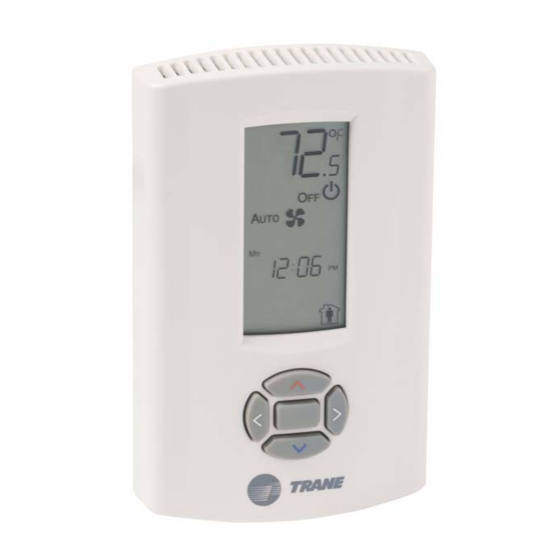
This section provides a description of the sensors, as well as part numbers and dimensions. Product Description ® The Trane programmable zone sensor (p/n X1379088401) can be used with UCP , Reliatel, and IntelliPak control units. It has the following features: • A liquid crystal display (LCD) with symbols for zone temperature, temperature setpoints, system operating modes, day of the week, time of day, and occupancy settings •... -
Page 5: Dimensions
General Information Dimensions The following illustration provides specific dimension details. The dimensions are the same for all models. 0.31 in (8 mm) 2.9 in (73.5 cm) 1.08 in (27.5 mm) 0.12 in (3 mm) 4.68 in (118.9 mm) TYP R.07 in 3.39 in (86 mm) (R1.80 mm) 0.24 in (6.00 mm) -
Page 6: Pre-Installation
Pre-Installation This section provides the following pre-installation information: • Location considerations • Height requirements • Mounting surfaces • Recommended wire lengths Location Considerations Placement of the sensor is critical to proper operation. When selecting a location, avoid the following: • Areas of direct sunlight •... -
Page 7: Wire Length
Pre-Installation Wire Length Maximum recommended wire lengths for the sensor are given in Table Table 1. Recommended wire lengths Maximum recommended wire length from unit Wire size controller to sensor Meters Feet 0.33 0–46 0–150 0.50 47–73 151–240 0.75 74–117 241–385 1.30 118–185... -
Page 8: Installation
Installation This section provides step-by-step installation instructions. Read through the pre-installation information before proceeding with the installation. Note: Before installing the sensor, ensure that: • A wire access hole is available at the sensor location • The wires are accessible through the hole •... -
Page 9: Wiring The Sensor
Installation Wiring the Sensor WARNING Hazardous voltage! Disconnect all electric power, including remote disconnects before servicing. Follow proper lockout/tagout procedures to ensure the power cannot be inadvertently energized. Failure to disconnect power before servicing could result in death or serious injury. NOTICE Equipment damage! Applying excessive voltage to the sensor will permanently damage it. - Page 10 Table 2. Programmable zone sensor wiring diagram YC* TE* YC* TE* 20–130 3–20 90–162 330–600 330–600 Commercial 3–25 ton split packaged model model self- packaged rooftops system 27.5–50 ton rooftops packaged number number contained units packaged rooftops rooftops 10th digit 10th digit (CSC) *CD/*CH/*SC/...
-
Page 11: Replacing The Cover
Installation Replacing the Cover To replace the cover: 1. Hook the cover over the top of the back plate. Apply light pressure to the bottom of the cover until it snaps in place. 2. Secure the cover by installing the security screw into the bottom of the cover. Security screw BAS-SVX17B-EN... -
Page 12: Applying Power To The Sensor
Installation Applying Power to the Sensor Restore power to the unit controller. The following sequence appears on the display: • The display lights up and all of the symbols appear for 2 seconds (see Figure Figure 2. Display with all the symbols appearing Zone temperature and setpoint temperature System settings... -
Page 13: Configuration
Configuration The programmable zone sensor is configured by selecting options to determine system and functional operations. The sensor can be configured to operate with one of the following units: • A constant-volume (CV) unit • A heat pump (HP) unit •... - Page 14 Configuration Table 3. Configuration options for sensors used with constant-volume (CV) heat pump (HP) units Option number Function Option value Default Description Configures the operation mode of the sensor. 0 = Constant-volume (CV) Note: To access option number 0, with the configuration Operation mode 1 = Heat pump (HP) screen showing, press the up and down arrows...
- Page 15 Configuration Table 3. Configuration options for sensors used with constant-volume (CV) heat pump (HP) units (continued) Option number Function Option value Default Description If the sensor is in a normal running state or in temporary 0 = No Display zone occupancy (timed override), the zone temperature temperature 1 = Yes...
- Page 16 Configuration Table 4. Configuration options for sensors used with variable-air-volume (VAV) units Option number Function Option Value Default Description Configures the operation mode of the sensor. 0 = Constant-volume (CV) Note: To access option number 0, with the configuration Operation mode 1 = Heat pump (HP) screen showing, press the up and down arrows (See Note)
- Page 17 Configuration Table 4. Configuration options for sensors used with variable-air-volume (VAV) units (continued) Option number Function Option Value Default Description Default temporary 1, 2, 3, 4, 5 (hours) Sets the default temporary override time in hours. override timer setting Displays current temperature Allows for field calibration in 0.1ºF (0.6ºC) increments of reading with any offsets: either the internal sensor on the sensor, or the remote...
-
Page 18: Operation
Operation This section describes sensor operations, explains sensor symbols, and provides the default settings. Set-up Procedures The following procedures show how to set up the programmable zone sensor for operation using the keypad and display. Procedures begin at the home screen (see Figure Figure 5. -
Page 19: Changing The Fan Setting (Cv/Hp Configuration Only)
Operation Changing the Fan Setting (CV/HP Configuration only) Fan Auto: The fan automatically 1. From the home screen, select the fan setting by pressing powers On and Off as needed to reach twice and then the selected temperature. 2. Press to select the desired fan setting. -
Page 20: Scheduling
Operation Scheduling The programmable zone sensor has a feature that “copies” the schedule for one of the five weekdays to the other four weekdays, and one of the two weekend days to the other weekend day. To use this feature, the sensor must be configured for 7 programmable days per week and scheduling must be completely blank. -
Page 21: Scheduling For Vav Occupied Periods
Operation Cooling setpoint 12. Press to select the cooling setpoint. The top arrow of the selected setpoint symbol and the cooling symbol flash. The current cooling setpoint appears (or dashes if nothing has been set). 13. Press to change the cooling setpoint for the period you are scheduling. -
Page 22: Temporary Override Set-Up (Cv/Hp Only)
Operation Temporary Override Set-up (CV/HP only) To override a setting for a specified period of time, start at the home screen and proceed as follows: 1. Press . The current temperature setpoint appears. The heating setpoint symbol flashes when selected. 2. -
Page 23: Locking Or Unlocking The Keypad
Operation Locking or Unlocking the Keypad You can lock or unlock the keypad to prevent changes as follows: Locked symbol 1. Begin at the home screen. 2. Press simultaneously for 4 seconds. The locked symbol appears on the display if the keypad is locked. If you press a keypad button, the locked symbol flashes three times. -
Page 24: Setpoint Only Display
Operation Setpoint Only Display You can configure the zone sensor to present setpoints instead of the space temperature on the main display. To display setpoints instead of space temperatures, follow these steps: 1. Begin at the home screen 2. Press the simultaneously for four seconds. - Page 25 Operation Table 5. Weekly operating schedule for sensors configured for CV or HP units Heating Cooling Period Start time Occupancy setpoint setpoint Morning ° ° Auto ° ° Auto Monday Evening ° ° Auto Night ° ° Auto Morning ° °...
- Page 26 Operation Table 6 can be used to create a weekly operating schedule for sensors configured for VAV units. Table 6. Weekly operating schedule for sensors configured for VAV units Warm-up Supply air or Supply air heat or unoccupied unoccupied setpoint heating cooling (modulating...
-
Page 27: Maintenance And Troubleshooting
Maintenance and Troubleshooting This section describes maintenance and troubleshooting for the programmable zone sensor. Error Codes An error code indicates that technical assistance may be required. Note: On the display, error codes toggle with the clock. Heat failure Indicates that there is an error in the heating system. Cool failure Indicates that there is an error in the cooling system. -
Page 28: Troubleshooting Table
Maintenance and Troubleshooting Troubleshooting Table Problem Solution Check the 24 Vac power supply at terminals 11 and 14 at the sensor. Verify that Display does not come on. the terminal block is properly positioned on its pins. Check for 22–32 Vdc between terminals 11 and 12 at the sensor. Check wiring if No communication to the unit controller. -
Page 29: Specifications
Specifications Sensor operating temperature 32 to 122ºF (0 to 50ºC) Storage temperature –67 to 176ºF (–55 to 80°C) Storage and operating humidity range 5% to 95%, non-condensing Accuracy ±2.0°F (±1.1°C) over a range of 50 to 90°F (10 to 32°C) ±4.0°F (±2.2°C) when outside this range Resolution 0.225ºF (0.2°C) over a range of 50 to 90ºF (10 to 32°C) -
Page 30: Declaration Of Ce Conformity
07/18/2008 Elecromagentic Immunity 07/18/2008 Mark of Compliance: European Contact Societ Trane (Epinal, France) 1, rue des Ameriques, B.P. 6 F-88191 Golbey Cedex, France Phone: (33) 329.31.73.00 Fax: (33) 329.81.24.98 This document valides CE conformity of the Programmable Zone Sensor module. -
Page 31: Notes
Declaration of CE Conformity Notes: BAS-SVX17B-EN... - Page 32 HVAC systems, comprehensive building services, and parts. For more information, visit www.Trane.com. Trane has a policy of continuous product and product data improvement and reserves the right to change design and specifications without notice. © 2010 Trane All rights reserved...
Need help?
Do you have a question about the X1379088401 and is the answer not in the manual?
Questions and answers