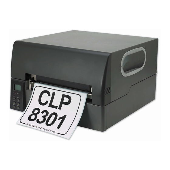
Citizen CLP-8301 User Manual
Thermal transfer bar code/label printer
Hide thumbs
Also See for CLP-8301:
- User manual (75 pages) ,
- Quick start manual (2 pages) ,
- Installation manual (2 pages)
Table of Contents
Advertisement
Quick Links
Advertisement
Table of Contents

Related Manuals for Citizen CLP-8301


Summary of Contents for Citizen CLP-8301
-
Page 2: Fcc Compliance Statement For American Users
EMC Directive (89/336/EEC)/EN55022, EN55024, EN61000-3-2 & EN61000-3-3 CITIZEN is a registered trade mark of CITIZEN WATCH CO., LTD., Japan CITIZEN es una marca registrada de CITIZEN WATCH CO., LTD., Japón Company names and product names in this manual are trademarks or registered trademarks of relevant companies. -
Page 3: Emi Compliance Statement For Canadian Users
EMI COMPLIANCE STATEMENT FOR CANADIAN USERS This equipment generates and uses radio frequency energy and if not installed and used properly, that is, in strict accordance with the manufacturer's instructions, may cause interference to radio and television reception. This digital apparatus does not exceed the Class A limits for radio noise emissions from digital apparatus set out in the Radio Interference Regulations of the Canadian Department of Communications. -
Page 4: Important Safety Instructions
Important Safety Instructions 1. Read all of these instructions and save them for later reference. 2. Follow all warnings and instructions marked on the product. 3. Unplug this product from the wall outlet before cleaning. Do not use liquid or aerosol cleaners. Use a damp cloth for cleaning. -
Page 5: Notice
Notice 1. Before use, be sure to read this manual. And keep it handy for reference when needed. 2. The contents of this manual may change without prior notice. 3. Reproduction, transfer, or transmission of the contents of this manual without prior consent is strictly prohibited. -
Page 6: Introduction
Introduction Thank you for purchasing a Citizen CLP series barcode label printer. This manual is designed to help you quickly understand the basic operations of this printer. Features This printer accurately prints clear bar codes and various character fonts on media such as labels and tags at high speeds. -
Page 7: Table Of Contents
Table of Contents FCC Compliance Statement for American Users......i CE Declaration for European Users..........i EMI Compliance Statement for Canadian Users ......ii Important Safety Instructions ............iii Notice ....................iv Trademark Acknowledgement............iv Introduction..................v Features .................... v Table of Contents ................ - Page 8 Chapter 5 Power ON and Using the Control Panel ....33 5.1 Connecting to a power outlet ..........33 5.2 Turning the printer ON.............34 5.3 Ready Mode and Menu Mode..........35 5.4 Navigating the Menu System ..........36 5.5 Changing Menu Values ............37 5.6 Permanently Saving Printer Settings ........38 5.7 Producing a Test or Configuration Print ........39 5.8 Turning the printer OFF............40 Chapter 6 Configuring Your Printer Using the Menus ....41...
- Page 9 − viii −...
-
Page 10: Chapter 1 Unpacking
Chapter 1 Unpacking Chapter Unpacking First open the carton and take out the top foam damper, then lift the printer main body out of the carton, holding the bottom of the printer firmly. Also keep the carton and packing materials as the printer must be packed with those materials for future shipment. -
Page 11: Printer Accessories
Chapter 1 Unpacking 1.1 Printer accessories First, you should check that all of the following accessories are put in the carton. If any are missing, please contact your supplier. • Power cord 1 piece • Ribbon takeup core 1 piece •... -
Page 12: Chapter 2 Safety Precautions
Chapter 2 Safety Precautions Chapter Safety Precautions This chapter describes safety precautions when using the printer. Please read and understand the precautions in this chapter before using the printer. Safety signs The various safety signs included in this manual and pasted on the printer are intended to inform you of the correct and safe handling of this printer and protect against personal injury and property damage. - Page 13 Chapter 2 Safety Precautions − 4 −...
- Page 14 Chapter 2 Safety Precautions − 5 −...
- Page 15 Chapter 2 Safety Precautions − 6 −...
- Page 16 Chapter 2 Safety Precautions − 7 −...
-
Page 17: Installation Precautions
Chapter 2 Safety Precautions − 8 −... -
Page 18: Chapter 3 Names And Functions Of Printer Parts
Chapter 3 Names and Functions of Printer Parts Chapter Names and Functions of Printer Parts This chapter describes the names and functions of each part of the printer. 3.1 Printer main body 1. Top cover The top cover is the upper part of the whole cabinet of the printer. To open lift evenly from both sides using the embossed patterns on the surface to help grip the cover and open it all the way until it stops at hinge stops. - Page 19 Chapter 3 Names and Functions of Printer Parts 2. Inside the Printer 1 Tear bar 11 Media holder disk 2 Platen 12 Media guide (on both sides) 3 Control panel 13 Media holder supporting plate 4 Transparent sensor (upper media sensor) 14 Media holder shaft 5 Transparent sensor guide 15 Media guide lock screw...
- Page 20 Chapter 3 Names and Functions of Printer Parts 3. Rear and side of printer − 11 −...
-
Page 21: Control Panel
Chapter 3 Names and Functions of Printer Parts 3.2 Control panel The control panel consists of an LCD displaying two lines of eight characters, two LEDs and six control keys. Two functions are assigned to each key except the MODE key. Indications LCD (Display) Shows the current printer status by a message on the display. - Page 22 Chapter 3 Names and Functions of Printer Parts Control keys On the control panel legend, in Ready mode, the text written ABOVE each key shows the key's function. In Menu mode, the text written BELOW each key shows the key's function. MODE key When the MODE key is pressed, the printer is placed into the Ready mode.
- Page 23 Chapter 3 Names and Functions of Printer Parts MODE key Printer enters the Menu mode, and the '∗ Page Setup' menu is shown on the LCD (Display). Key functions in the Menu mode MENU key Selects the next Group Menu or Menu Item. (See P35-37) UP key •...
-
Page 24: Chapter 4 Media (Paper) And Ribbon
Unless otherwise specified, the term 'media,' 'paper,' 'page,' 'labels,' or 'tags' is referring to any media that is being printed using the printer. 4.1 Types of media We recommend the use of CITIZEN media for optimal print quality. Types of media available for this printer: • Center-punched hole tag •... - Page 25 Chapter 4 Media (Paper) and Ribbon ♦ Center-punched hole tag Holes (2.5mm diameter) are perforated lengthwise along the central line of the tag. ♦ Black mark tag Black marks are printed on the back of the tag at the center or on the right side in the direction of feed.
- Page 26 Chapter 4 Media (Paper) and Ribbon Label Media with adhesive material on the back are referred to as labels. Labels are peeled off the liner piece by piece and stuck to a product or item. ♦ Labels with inter-label gap There are gaps between labels.
-
Page 27: Media Size
Chapter 4 Media (Paper) and Ribbon 4.2 Media size − 18 −... -
Page 28: Loading Media (Paper)
Chapter 4 Media (Paper) and Ribbon 4.3 Loading media (paper) This printer is designed to align the center of the media (paper) with the center of the printhead, regardless of media (paper) width. Refer to the scale on the media guide plate (see P30) for aligning media (paper) or ribbon. - Page 29 Chapter 4 Media (Paper) and Ribbon (3) Unlock the media guide lock screw and move both side media guides to their maximum outward position. Printhead assembly Transparent sensor guide Media guide (on both sides) Media guide lock screw Transparent sensor guide release lever Printhead release lever 4.
- Page 30 Chapter 4 Media (Paper) and Ribbon 5. Route the roll media over the platen out to the front of the printer. 6. First lower the transparent sensor guide and push down gently to lock. Then lower the printhead assembly fully and push down firmly on the top edge by the ribbon holders to lock in place. Printhead assembly Transparent sensor guide Path of outward-wound roll media...
- Page 31 Chapter 4 Media (Paper) and Ribbon 7. The roll media is now loaded. Lastly close the top cover. Fanfold media 1. Remove ribbon holder disks (two) from the ribbon holder assembly. Place the media holder shaft onto the round notches on the media guides and media holder shaft supporting plates on both sides. 2.
-
Page 32: Loading The Ribbon
Chapter 4 Media (Paper) and Ribbon 4.4 Loading ribbon We recommend the use of CITIZEN Thermal Transfer Ribbon for optimal print quality. This printer is designed to align the center of the media (paper) with the center of the printhead, regardless of media width. - Page 33 Chapter 4 Media (Paper) and Ribbon 2. Two ribbon mandrels are used for loading ribbon; one is inserted in the supply (unused) ribbon core and the other is inserted the ribbon takeup core. Wind the ribbon from the takeup mandrel until most wrinkles are no longer visible.
- Page 34 Chapter 4 Media (Paper) and Ribbon 3. Perform the following sequence; open the top cover all the way until it stops at hinges, and unlock the printhead assembly by pushing the printhead release lever and raise it until it stops and stands upright.
- Page 35 Chapter 4 Media (Paper) and Ribbon 5. Temporarily winding the ribbon with a length of about 300 mm (1 ft) unwound between mandrels around the lower, bottom side of the printhead assembly, first fit both sockets of the ribbon takeup and supply mandrels, then snap into place both knobs of the ribbon takeup and supply mandrels.
-
Page 36: Ribbon Tension Adjustments
Chapter 4 Media (Paper) and Ribbon Ribbon tension adjustments The ribbon tension should be adjusted as needed according to the media (paper) width to prevent ribbon from wrinkling. To increase tension torque, turn the ribbon supply mandrel (the deeper side viewed from the front of the printer) knob clockwise until the required number is obtained on the scale, while stopping the gear with a coin inserted in the slit on the ribbon mandrel support and held down. -
Page 37: Printhead Adjustments
Chapter 4 Media (Paper) and Ribbon 4.5 Printhead adjustments Printhead adjustments should be made according to the type of media (paper), using the printhead adjustment lever located on the back of the printhead assembly. Generally, for media with moderate stiffness (labels), position the printhead adjustment lever to the middle of the range to put the printhead in middle position, and for media with greater stiffness (tags or card), lower the adjustment lever to the lower level to put the printhead in forward position. -
Page 38: Media Sensor Adjustments
Chapter 4 Media (Paper) and Ribbon 4.6 Media sensor adjustments The printer is equipped with the upper and lower media sensors that are moved separately. Both media sensors detect the presence of media and top of form of media except continuous roll media. -
Page 39: Selecting Media Sensor And Autocal Mode
Chapter 4 Media (Paper) and Ribbon 3. When the media is a center-punched hole or notched tag, first align the hole or notch with the lower sensor position mark 'T.' At this point, read the value of the scale on the media guide plate pointing the 'T' mark. -
Page 40: Avoiding Wrinkling Of The Ribbon
Chapter 4 Media (Paper) and Ribbon 4.7 Avoiding wrinkling of the ribbon If the ribbon wrinkles, the ribbon tension on either side of the ribbon will not be even. Remove slack on the ribbon in the following order: Removing slack on winding side of ribbon (in front of printhead) 1. -
Page 41: Removing Slack On Feeding Side Of Ribbon (Behind Printhead)
Chapter 4 Media (Paper) and Ribbon Removing slack on feeding side of ribbon (behind printhead) 1. Open the top cover all the way until it stops at hinges and unlock the printhead assembly by pushing the printhead release lever and open it towards the left side of the printer all the way until it stops and stands upright. -
Page 42: Chapter 5 Power On And Using The Control Panel
Chapter 5 Power ON and Using the Control Panel Chapter Power ON and Using the Control Panel After loading the media and ribbon, connect the power cord and turn your printer on. 5.1 Connecting to a power outlet First plug the power cord into the AC power input on the back of the printer, then plug the other end of the power cord into the AC power outlet. -
Page 43: Turning The Printer On
Chapter 5 Power ON and Using the Control Panel 5.2 Turning the printer ON Turn ON the power switch. • Press "|" for ON. • Press "O" to turn off the printer. Once the power is turned ON, the following initial messages are displayed on the screen for about three seconds. -
Page 44: Ready Mode And Menu Mode
Chapter 5 Power ON and Using the Control Panel 5.3 Ready Mode and Menu Mode This section describes the operation flow of the Ready mode and Menu mode. This printer can be easily operated using the six keys on the control panel. −... -
Page 45: Navigating The Menu System
Chapter 5 Power ON and Using the Control Panel 5.4 Navigating the Menu System − 36 −... -
Page 46: Changing Menu Values
Chapter 5 Power ON and Using the Control Panel 5.5 Changing Menu Values − 37 −... -
Page 47: Permanently Saving Printer Settings
Chapter 5 Power ON and Using the Control Panel 5.6 Permanently Saving Printer Settings − 38 −... -
Page 48: Producing A Test Or Configuration Print
Chapter 5 Power ON and Using the Control Panel 5.7 Producing a Test or Configuration Print − 39 −... -
Page 49: Turning The Printer Off
Chapter 5 Power ON and Using the Control Panel 5.8 Turning the printer OFF − 40 −... -
Page 50: Chapter 6 Configuring Your Printer Using The Menus
Chapter 6 Configuring Your Printer Using the Menus Chapter Configuring Your Printer Using the Menus This chapter explains all the possible menu options for configuring the barcode printer. Refer to Chapter 5 for information on the operation of the menus system and which keys perform which actions. 6.1 The Group Menu −... -
Page 51: Page Setup Menu
Chapter 6 Configuring Your Printer Using the Menus 6.2 Page Setup Menu − 42 −... -
Page 52: System Setup Menu
Chapter 6 Configuring Your Printer Using the Menus 6.3 System Setup Menu − 43 −... - Page 53 Chapter 6 Configuring Your Printer Using the Menus − 44 −...
-
Page 54: After Print Menu
Chapter 6 Configuring Your Printer Using the Menus 6.4 After Print Menu − 45 −... -
Page 55: Interface Setup Menu
Chapter 6 Configuring Your Printer Using the Menus 6.5 Interface Setup Menu − 46 −... -
Page 56: Permanently Saving Settings Menu
Chapter 6 Configuring Your Printer Using the Menus 6.6 Permanently Saving Settings Menu 6.7 Test Mode Menu The Test Mode Menu allows the printer to produce configuration prints for current settings, machine information such as distance counter and test samples. It also allows for head checks, resetting the non-volatile memory to factory default values and a hex dump mode. -
Page 57: Menu Mode Description
Chapter 6 Configuring Your Printer Using the Menus 6.8 Menu Mode Description − 48 −... - Page 58 Chapter 6 Configuring Your Printer Using the Menus − 49 −...
- Page 59 Chapter 6 Configuring Your Printer Using the Menus − 50 −...
- Page 60 Chapter 6 Configuring Your Printer Using the Menus − 51 −...
- Page 61 Chapter 6 Configuring Your Printer Using the Menus − 52 −...
-
Page 62: Chapter 7 Troubleshooting
Chapter 7 Troubleshooting Chapter Troubleshooting When an error occurs, an error message is displayed on the LCD panel. This chapter describes corrective actions to be taken when error message is received or problems or difficulties are experienced. 7.1 Items to check in case of trouble −... - Page 63 Chapter 7 Troubleshooting − 54 −...
-
Page 64: Error Messages And Corrective Actions
Chapter 7 Troubleshooting 7.2 Error messages and corrective actions − 55 −... - Page 65 Chapter 7 Troubleshooting − 56 −...
-
Page 66: Chapter 8 Maintenance
Therefore, be sure to clean the printhead, platen and media path periodically. The amount of cleaning will depend on the volume of media being printed and the quality of the consumables and media used in the printer. Genuine Citizen consumables will be you the best performance. -
Page 67: Cleaning Method
Chapter 8 Maintenance 8.2 Cleaning method − 58 −... -
Page 68: Chapter 9 Specifications
Chapter 9 Specifications Chapter Specifications 9.1 General specifications − 59 −... -
Page 69: Interfaces
Chapter 9 Specifications 9.2 Interfaces 1 Serial interface Specifications Transfer method: Start stop synchronous dual communication system Signal level: RS-232C Baud rate: 2400, 4800, 9600, 14400, 19200, 38400, 57600, 115200 bps Data bits: 7 or 8 Start bits: Stop bits: 1 or 2 Parity: Even, odd, or none... - Page 70 Chapter 9 Specifications DTR protocol DTR signal "Ready (High)" level requirements: The following must be satisfied: • Printer is on line. • Receive buffer has more than 128 bytes available. Note: When receive buffer has less than 128 bytes available, DTR signal becomes "Busy (Low)" level and this "Busy (Low) level is kept until receive buffer has at least 1K bytes available.
-
Page 71: Parallel Interface
Chapter 9 Specifications 2 Parallel interface − 62 −... -
Page 72: Pcmcia Memory Card (Factory-Installed Option)
Chapter 9 Specifications 9.3 PCMCIA Memory Card − 63 −... -
Page 73: Print Width
Chapter 9 Specifications 9.4 Print width − 64 −... -
Page 74: Movable Sensors
Chapter 9 Specifications 9.5 Movable sensors − 65 −... -
Page 75: Environmental Requirements
Chapter 9 Specifications 9.6 Environmental requirements Printer operating conditions for ensuring print quality 5°C − 40°C Operating temperature: 25% − 85% RH (non-condensing) Humidity: Printer storage conditions -20°C − 60°C Storage temperature: 25% − 85% RH (non-condensing) Humidity: (Printer should be stored in a condition that the printhead is up and paper and ribbon are removed.) −... - Page 77 363 Van Ness Way, Suite 404 Torrance, CA 90501. USA Tel: (310) 781-1460 Fax: (310) 781-9152 http://www.citizen-systems.com Mettinger Strasse 11 Park House, 643-651 Staines Road D-73728, Esslingen Feltham, Middlesex, TW14 8PA Germany United Kingdom Tel: +49 (0) 711 3906 420...
Need help?
Do you have a question about the CLP-8301 and is the answer not in the manual?
Questions and answers