Table of Contents
Advertisement
Quick Links
Advertisement
Table of Contents

Related Manuals for Sony CDU701


Summary of Contents for Sony CDU701
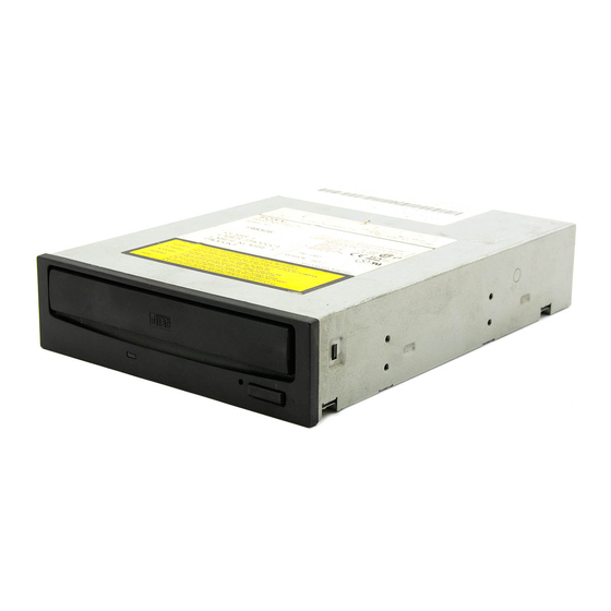
- Page 1 3-864-284-62(1) CDU701 CD-ROM Drive Unit User’s Guide...
- Page 2 CDU701 CD-ROM Drive Unit User’s Guide ©1998 by Sony Corporation Printed in U.S.A.
- Page 3 Owner’s Record The model and serial numbers are located on the top side of the drive. Record these numbers in the spaces provided below. Refer to them whenever you call upon your sales representative regarding this product. Model No. __________________ Serial No.
- Page 4 The CLASS 1 LASER PRODUCT label is located LASER KLASSE 1 on the top of the drive. PRODUKT Bei diesem CD-ROM-Laufwerk CDU701 handelt es sich um ein Laser-Produkt der Klasse 1. LUOKAN 1 LASERLAITE Ein entsprechender Aufkleber mit der Beschriftung...
- Page 5 Model No.: CDU701 Responsible Party: Sony Electronics Inc. Address: 1 Sony Drive, Park Ridge, NJ. 07656 USA Telephone No.: 201-930-6970 This device complies with Part 15 of the FCC Rules. Operation is subject to the following two conditions: (1) This device may not cause harmful interference, and (2) This device must accept any interference received, including interference that may cause undesired operation.
-
Page 6: Table Of Contents
Contents Introduction Features ....................6 Software Requirement ................ 7 Example of System Setup ..............7 Location and Function of Parts and Controls Front Panel ..................8 Rear Panel ..................9 Precautions Installing the Drive in Your Computer Preparation ..................11 Setting the Jumpers ................ -
Page 7: Introduction
• Outputs 16-bit digital audio data over the ATA interface. • Equipped with audio line output and headphones jack for audio CD playback. Note: The CDU701 is not equipped with an ADPCM audio cir cuitr y required to suppor t CD-R OM XA and CD-I compatib le audio modes. -
Page 8: Software Requirement
Software Requirement To access data on CD-R OM discs, the appr opriate de vice driver and MSCDEX (supplied with the host adapter) must be installed in your computer when the OS is MS-DOS/Windo ws 3.1. See the man ual that comes with the host adapter for details. The application software y ou need f or using the data on a CD-R disc depends on the type and f... -
Page 9: Location And Function Of Parts And Controls
Location and Function of Parts and Controls Front Panel 1 Disc drawer Accepts a CD-ROM disc on its tray. 2 Headphones jack Accepts a stereo headphones set. Analog audio signals are output. 3 Volume control Controls the volume level of sound output from the headphones jack 2 . -
Page 10: Rear Panel
Rear Panel Pin 1 1 2 3 1 Unused 2 ANALOG AUDIO connector Outputs analog audio signals. 3 Configuration Jumpers See page 12 for details. 4 INTERFACE CONNECTOR (IDE bus) Connect to IDE host adapter using a connecting cable. 5 DC INPUT (power-in) connector Connect to the power supply of the host computer. -
Page 11: Precautions
Precautions Installation • Avoid placing the drive in a location subject to: – high humidity – high temperature – excessive dust – mechanical vibration – direct sunlight • Do not force the power cable. It is keyed to protect the drive. Operation •... -
Page 12: Installing The Drive In Your Computer
CD-ROM drive unit into y our per sonal computer using the IDE Host Adaptor (A TA-Compliant). To connect the CDU701 directl y to the PC’ s IDE por t, consult y our PC man ufacturer f or instruction. -
Page 13: Setting The Jumpers
IDE Card, set the Hard Disk Drive as MASTER and the CDU701 as SLAVE. • If the CDU701 is the only device connected to the IDE Card, set the CDU701 as MASTER. However, it should be noted that some per... -
Page 14: Opening The Computer
Opening the Computer If your computer has its rear side covered by a plastic panel attached with plastic hook pad, pull it off. Remove the plastic panel. Computer Rear plastic panel Remove the cover mounting screws. Cover mounting screw Remove the screws. Remove the cover of the computer. -
Page 15: Preparing A Space For The Drive
Preparing a Space for the Drive Remove the screws and brackets securing the floppy disk drive and the lower drive bay blanking plate. Floppy disk drive Lower dirve bay blanking plate Remove the screws and brackets. Disconnect the floppy disk drive. Floppy disk drive Remove the floppy disk drive and the blanking plate. -
Page 16: Mounting The Drive
Mounting the Drive If mounting rails are necessar y, attac h them to the drive in the same wa y as y our flopp y disk drive and slide the drive into the lo wer drive ba y. If mounting rails are not required in y our system, scre w the drive in place . -
Page 17: Connecting The Drive
Connecting the Drive Connect the drive to the computer with the f ollo wing connector • DC INPUT connector • AUDIO OUT connector (if you plan to connect audio equipment) • INTERFACE CONNECTOR. INTERFACE CONNECTOR DC INPUT connector AUDIO OUT connector DC INPUT connector The pin assignment is as f... - Page 18 AUDIO OUT connector The pin assignment is as f ollo ws: Audio Signal R signal ground ground L signal INTERFACE CONNECTOR Firmly insert one end of the interface cable into the INTER- FACE CONNECTOR. Pin 1 INTERFACE CONNECTOR INTERFACE cable Attach the other end of the cable to the host adapter.
-
Page 19: Mounting The Host Adapter
Mounting the Host Adapter Install the host adapter in one of the a vailab le system e xpansion slots of y our computer . Refer to the operating instructions inc luded with the host adapter for complete instructions on installation and settings. -
Page 20: Reassembling The Computer
Reassembling the Computer Reinstall the floppy disk drive in the top drive bay. Reinstall the floppy disk drive. Reconnect the interface cables to the floppy disk drive. Fasten the screws and front brackets as they were before. Tuck the cables behind the drives so that they do not protrude above the power supply module. -
Page 21: Installing The Software Driver
Both Micr osoft CD-R OM Extensions (MSCDEX) or equiv alent and Son y’s De vice Driver are required to run the CDU701 under the MS-DOS and Windo ws 3.1 en vironment. Theref ore , prior to loading the installation diskette... -
Page 22: Operating The Drive
Operating the Drive This section describes ho w to star t the drive and eject a disc. Starting the Drive Turn on the power of your computer. Press the eject button. The drawer comes out automatically. Press the eject button. Place a disc in the drawer with its label side up. - Page 23 Note: When the drive is set up in ver tical position, use the disc loc ks to pre vent y our disc fr om falling. See “Ho w to Use the Disc Loc ks” on page 24 for details. Disc locks Gently push the drawer or press the eject button to close the drawer.
-
Page 24: Ejecting The Disc
Ejecting the Disc To eject the disc, press the eject b utton on the fr ont panel. The dra wer comes out automaticall Press the eject button. Note: The eject b utton does not w ork if it is disab led b y: –... -
Page 25: How To Use The Disc Locks
How to Use the Disc Locks The disc tra y has f our disc loc ks that pre vent the disc fr om falling when the drive is set up in ver tical position. Disc locks Note: When the drive is used in horizontal position, you do not need to lock the disc. - Page 26 When the drive’s right side is down To facilitate disc handling, set the disc loc ks B, C and D into the loc ked position, and lea ve the disc loc k A in the unloc ked position. Top side Right side When the drive’s left side is down To facilitate disc handling,...
-
Page 27: Specifications
Specifications General Host interface ATA-PI compliant Disc Acceptable discs CD-Digital A udio discs CD-ROM mode-1 data discs CD-ROM mode-2 f orm1/f orm2 data discs CD-ROM XA discs (readab Audio-combined CD-R OM discs CD-I discs (readable) CD-I Ready discs (readable) CD Bridge discs Photo CD discs (single and multi session) CD EXTRA discs Video CD discs, CD TEXT discs... -
Page 28: Environmental Conditions
Environmental conditions Operating Temperature 5 °C to 50 °C (41 °F to 122 °F) Humidity 10 % to 90 % (Max wet b ulb 29 °C) Atmosphere Non-condensing Non-operating/Storage Temperature –30 °C to 50 °C (–22 °F to 122 °F) Humidity 10 % to 90 % Atmosphere... - Page 29 Dimension diagram Important: The o verhang of the scre ws should not e xceed 6.0 mm fr om the surface of the side panels or the bottom plate 42.3 47.5 79.25 Unit mm(inch) Specifications...
Need help?
Do you have a question about the CDU701 and is the answer not in the manual?
Questions and answers