Table of Contents
Advertisement
Quick Links
Video Disk
Recorder
Operating Instructions
Before operating the unit, please read this manual
thoroughly and retain it for future reference.
Note
The supplied CD-ROM includes operation manuals
for the DSR-DR1000/DR1000P Video Disk Recorder
(English, Japanese, French, German, Italian and Spanish versions).
For more details, see "Using the CD-ROM Manual" on page 14.
DSR-DR1000/DR1000P
© 2002 Sony Corporation
3-742-658-11 (1)
Advertisement
Table of Contents

Related Manuals for Sony DSR-DR1000


Summary of Contents for Sony DSR-DR1000
- Page 1 Note The supplied CD-ROM includes operation manuals for the DSR-DR1000/DR1000P Video Disk Recorder (English, Japanese, French, German, Italian and Spanish versions). For more details, see “Using the CD-ROM Manual” on page 14. DSR-DR1000/DR1000P...
- Page 2 Record these numbers in the spaces provided below. Refer that may be of sufficient magnitude to to them whenever you call upon your Sony dealer constitute a risk of electric shock to regarding this product.
-
Page 3: Important Safety Instructions
Caution Important Safety Instructions Television programs, films, video tapes and other materials may be copyrighted. • Read these instructions. Unauthorized recording of such material may be contrary • Keep these instructions. to the provisions of the copyright laws. • Heed all warnings. •... - Page 4 La conformité à ces directives implique la conformité aux AVERTISSEMENT normes européennes suivantes: • EN60065: Sécurité des produits Afin d’éviter tout risque d’incendie ou • EN55103-1: Interférences électromagnétiques (émission) d’électrocution, ne pas exposer l’appareil • EN55103-2: Sensibilité électromagnétique (immunité) à la pluie ou à l’humidité. Ce produit est prévu pour être utilisé...
- Page 5 VORSICHT 1. Für Ihren privat genutzten Videorecorder muß eine Um Feuergefahr und die Gefahr eines elektrischen Fernseh-Rundfunk-Genehmigung beantragt Schlages zu vermeiden, darf das Gerät weder Regen noch werden, sofern nicht bereits eine Genehmigung für Feuchtigkeit ausgesetzt werden. ein Fernsehgerät desselben Haushaltes vorliegt. Im Um einen elektrischen Schlag zu vermeiden, darf das geschäftlichen Bereich ist jeder einzelne Gehäuse nicht geöffnet werden.
- Page 6 Grabadora de disco duro ATTENZIONE ADVERTENCIA Per evitare il pericolo di incendi o scosse elettriche, non esporre l’apparecchio alla pioggia o all’umidità. Para evitar el riesgo de incendios o electrocución, no Per evitare scosse elettriche, non aprire l’apparecchio. exponga la unidad a la lluvia ni a la humedad. Per le riparazioni, rivolgersi solo a personale qualificato.
-
Page 7: Table Of Contents
Table of Contents Chapter 1 Overview Features..............11 DVCAM Format ............11 Supporting Variety of Input/Output Interfaces ..... 11 Compact Size ..............12 Facilities for High-Efficiency Editing......12 Special Hard Disk Functions......... 12 Other Features ............... 13 Using the CD-ROM Manual ........14 CD-ROM System Requirements........ - Page 8 Starting Recording at an Alarm Input (Pre-Alarm Recording) ............39 Playback ..............39 Playback Procedure............39 Recording and Playing Back Simultaneously ....40 Setting Points A and B for Repeat Playback....41 Repeat Playback —Automatic Cyclical Playback ..43 Connecting Multiple Units for Simultaneous Playback (Multi-Si- multaneous Playback)..........
- Page 9 Chapter 6 Menu Setting Menu Organization ............63 Menu Contents............66 Setup Menu ..............66 Changing Menu Settings ..........77 Buttons Used to Change Settings........77 Changing the Settings of Basic Items ......77 Displaying Enhanced Items .......... 79 Changing the Settings of Enhanced Items ....79 Returning Menu Settings to Their Factory Default Settings ..............
-
Page 11: Features
There are two recording modes: 2-channel mode (48-kHz The DSR-DR1000/DR1000P supports the jog, shuttle, and sampling and 16-bit quantization), which offers sound variable playback modes found on conventional VTRs, quality equivalent to the DAT (Digital Audio Tape) together with jog sound. -
Page 12: Compact Size
(for DSR-DR1000), black level This mode is suitable for meteorological and biological (for DSR-DR1000P), and chroma phase using the setup observations, which require long continuous recording menu. -
Page 13: Other Features
Compatible with wide-screen aspect ratio (16:9) Via the two RS-422A connectors, multiple DSR-DR1000/ DR1000P units can be connected in a cascade connection, The unit can record and play back aspect ratio information. for simultaneous playback without delay. This is... -
Page 14: Using The Cd-Rom Manual
Using the CD-ROM Manual The supplied CD-ROM includes operation manuals for the A PDF file of the operation manual opens. DSR-DR1000/DR1000P Video Disk Recorder (English, Japanese, French, German, Italian and Spanish versions). Note If you lose the CD-ROM disc or become unable to read its... -
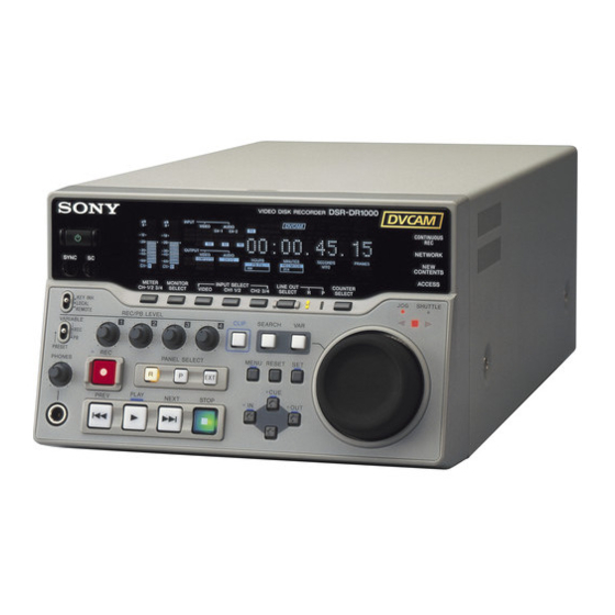
Page 15: Location And Function Of Parts
Location and Function of Parts Front Panel 0 Status indicators qa Audio level meters a 1 switch 2 SC/SYNC control 3 Control mode selector 4 PHONES connector and control knob 5 METER CH-1/2 3/4 button 9 COUNTER SELECT button 6 MONITOR SELECT button 8 LINE OUT SELECT button and indicators 7 CLIP button 1 Display section (see page 18) - Page 16 b SC (subcarrier phase)/SYNC (synchronization When CH-1/2 mode is selected with the METER CH-1/ phase) control 2 3/4 button: Turn the SC control to accurately adjust the subcarrier Audio level meters PHONES MONITOR phase of the composite video output signal of the unit with connector connector respect to the reference video signal.
-
Page 17: Status Indicators
i COUNTER SELECT button • CH-1 and CH-2 (channels 1 and 2) Selects the type of time data to be shown in the time Both the CH-1 and CH-2 indicators light. counter display. Each press of this button cycles through When CH-3/4 mode is selected with the METER CH-1/ the following three indicator display options: 2 3/4 button:... -
Page 18: Display Section
1 Display section 2 INPUT signal display section 3 Time data type indicators 4 DVCAM indicator 5 KEY INHI indicator 6 REC INHI indicator 7 Disk end alarm indicator 8 REPEAT indicator 9 Time counter display 0 Remote mode indicators qa VITC indicator qs PB Fs display qd REC MODE display... - Page 19 You can change the channel selection with the AUDIO U-BIT: User bit data OUTPUT menu item (see page 74). TC: SMPTE time code (for DSR-DR1000) or EBU time code (for DSR-DR1000P) b INPUT signal display section Indicates the input video and audio signal formats selected d DVCAM indicator with the INPUT SELECT buttons (i.LINK, VIDEO, CH1...
- Page 20 COUNTER SELECT button and the TC SELECT menu • Video test signal (selected with the INT VIDEO SG item (see page 70). menu item (see page 71) generated by the internal signal Also used to display error messages, edit data, setup menu generator data, etc.
- Page 21 The selection made with this button is indicated by the Note AUDIO CH-2 3/4 indicators in the INPUT signal display If you set the VARIABLE switch to REC, set the audio section (see page 19). input levels, and then set the switch to PB, the audio input When analog audio is selected, the signal input to the levels return to the preset levels.
-
Page 22: Play Button
When you press this button, it lights and playback begins. c EXT (external) button If you press this button during recording, the recording When you have connected multiple DSR-DR1000/ operation is stopped and this unit enters playback mode. DR1000P units in a cascade sequence and want to control... -
Page 23: Menu Button
a MENU button See the description of the search dial 4 for more Press this button to display the menu on the monitor screen information about the jog and shuttle modes. and the time counter display. Press it again to exit the menu b VAR (variable) button display. -
Page 24: Rear Panel
Normally you should leave this connectors to make cascade connections between several switch in the on position and power the unit on and off with DSR-DR1000/DR1000P units. the power switch on the front panel. Use the IN(R) connector to connect an editor. When... - Page 25 VIDEO button in the video/ R−Y/C C signal audio input selection section. The selection is indicated by (3.58 MHz for DSR-DR1000/ the VIDEO indicators in the INPUT signal display section. 4.43 MHz for DSR-DR1000P) The analog video signals that can be input to these B−Y...
- Page 26 When in 2 CH (48 kHz) mode: Input Audio channels on which input connectors signals are recorded Input Audio channels on which input connectors signals are recorded AUDIO IN 1/3 Audio channels 1 and 3 AUDIO IN 1/3 Audio channel 1 AUDIO IN 2/4 Audio channels 2 and 4 AUDIO IN 2/4...
- Page 27 c MONITOR connector (RCA phono jack) selected with the MONITOR SELECT button and This connector outputs audio signals for monitoring. The METER CH-1/2 3/4 button on the front panel (see page audio signals to be output from this connector can be 16).
- Page 28 Location and Function of Parts...
-
Page 29: Setting The Date And Time
Preparations Chapter To change a numeric value Setting the Date and Time Press the J(CUE) button to increase a value. Press the j button to decrease a value. To return a value to the factory default setting (2002/01/01 00: 00: 00) press the RESET button. When you start this unit for the first time, you should set the data and time. -
Page 30: Displaying Time Data And Operation Mode Indications
Stop mode F. FWD Fast forward mode E DSR-DR1000/DR1000P operation mode Rewind mode a) This character (.) can appear on the DSR-DR1000 only. The PREROLL Preroll mode character to appear in these two columns is always a colon PLAY Playback mode (servo unlocked) ( : ) on the DSR-DR1000P. -
Page 31: Using The Internal Time Code Generator
Display Operation mode Note When the REMOTE indicator in the front panel display REC-PAUSE Temporary stop of recording section is lit, the COUNTER SELECT button does not REC LOCK Record mode (servo locked) operate during recording or playback. In such cases, use JOG STILL Still picture in jog mode the external equipment connected to the REMOTE IN (R)/... -
Page 32: Synchronizing Internal And External Time Codes
RUN MODE “FREE RUN” or “REC RUN” usual status. DF MODE Normally “ON (DF)” (for DSR-DR1000 Note only) The set data may be lost if you power off the unit while the above saving operation is in progress. Wait Display the TC PRESET menu. -
Page 33: Making Basic Network Settings
with the external time code input to the unit via the i.LINK Making Basic Network interface. When the TC SELECT menu item is set to VITC, the Settings internal time code generator synchronizes to the time code (VITC) of video input signals. Once an external time code signal has been input, the To use this unit in a LAN environment (see page 53), you internal time code advancement mode and frame count... -
Page 34: To Set The Subnet Mask
To Set the Subnet Mask Select SUB NET MASK in the NETWORK CONTROL screen and press the k(OUT) button. The default value 255.255.255.000 appears, with the leftmost digit 2 flashing. Change the value by using the menu and clip operation buttons in the same way as with the IP address. -
Page 35: Recording
Recording and Playback Chapter Settings for Recording Recording Use the following procedure to make normal recording settings on this unit connected with a player. To perform This section describes the necessary settings and normal recording, you need to set the REC MODE menu operations to perform recording on this unit. - Page 36 When controlling this unit from an editing control unit Video input signal Corresponding Lit indicator connected to the REMOTE IN (R)connector, see “Control (input connector) INPUT in the INPUT mode selector” on page 16 and the description of the SELECT signal display button section...
-
Page 37: Recording Procedure
• When, in 4-channel mode, analog audio is selected for all four channels (channels 1/2 and 3/4), the same analog audio signals are recorded on channels 1 and Recorder 3 and on channels 2 and 4, respectively. (this unit) When manually adjusting audio input levels, with the Control mode VARIABLE switch on the front panel set to REC, use selector... -
Page 38: To Set Cue Points
For more information on this operation, see “Cueing Up a Operation Do this: Desired Cue Point” on page 46. Inhibit the SUPER Set the CHARA. DISPLAY connector from outputting menu item (see page 68) to To delete a cue point text information (time data, OFF. -
Page 39: Recording Continuously By Overwriting Old Content (Continuous Recording)
Recording Continuously by Playback Overwriting Old Content (Continuous Recording) This section describes the settings and operations Continuous recording allows you to continue recording for necessary to perform playback on this unit. The same extended periods by overwriting older recorded content. settings and operations apply whether you are using the To perform continuous recording, you need to set the REC unit as part of an editing system, for dubbing, or as a stand-... -
Page 40: Recording And Playing Back Simultaneously
Note Switch Setting Program playback may not be seamless during 75 Ω termination ON (or attach a 75 Ω terminator.) simultaneous recording and playback. switch Input switch Set according to the type of input signal from this unit. R button P button Press the PLAY button. -
Page 41: Setting Points A And B For Repeat Playback
R and P lit at same time: Output signals are selected by Note the R and P buttons in the PANEL SELECT section. When performing repeat playback using points A and B as Recording signals are output when the R button is lit, the playback start and end points, make sure that the and playback signals are output when the P button is REPEAT TOP and REPEAT END menu items (see page... - Page 42 SETUP MENU >> REP TOP SETUP MENU Operational OPERATIONAL FUNCTION OPERATIONAL FUNCTION REPEAT FUNCTION DISPLAY CONTROL Time counter display Time counter display REPEAT MODE :OFF TIME CODE REPEAT TOP :D.TOP SETUP BANK OPERATION REPEAT END :V.END NETWORK CONTROL A PRESET MENU GRADE :BASIC B PRESET...
-
Page 43: Repeat Playback -Automatic Cyclical Playback
Press the j button to select “A PRESET.” Note The new setting may be lost if you power off the unit SETUP MENU >> A preset during the saving operation. Wait until the saving OPERATIONAL FUNCTION operation is completed before powering the unit off. REPEAT FUNCTION Time counter display :OFF... -
Page 44: Connecting Multiple Units For Simultaneous Playback (Multi-Simultaneous Playback)
Connecting Multiple Units for Simultaneous Playback (Multi-Simultaneous Playback) You can connect multiple DSR-DR1000/DR1000P units case, the REMOTE I/F menu item (see page 74) must be in a cascade connection for simultaneous playback of set to 9PIN(PARA). various different scenes. The figure below shows how to... -
Page 45: Search Operations Via External Equipment
The maximum shuttle playback speed can be changed with control equipment connected to the iS400(i.LINK) the MAX SRCH SPEED menu item (see page 67). connector. To search while playing at fast speeds Jog: Press the SEARCH button or search dial to select jog Shuttle: Use this mode to view color video playback at mode (the JOG indicator lights). -
Page 46: Cueing Up A Desired Cue Point
Cueing Up a Desired Cue Point with the J (CUE) button held down makes the cue pointer When you have started this unit, the cue pointer is automatically positioned at the top of the disk (or the start jump to the second-registered cue point, a third press point of the first-recorded clip). -
Page 47: Chapter 4 Clip Operations
Clip Operations Chapter DISK MENU DISK MENU Clips DELETETC PRESET DELETE PROTECT CLIP DELETE ALL CUE ALL CLIP Data recorded on the hard disk of this unit is managed in units of clips. The section from the recording start point (Rec In) to the recording end point (Rec Out) is defined as a single clip and automatically assigned a clip name. -
Page 48: To Search In Clip Units (Clip Jump)
To display the protect operation menu, select PROTECT To Search in Clip Units in the Disk menu and press the k (OUT) button. In the protect operation menu, select CLIP or ALL CLIP and (Clip Jump) press the SET button. Individual clips or all clips are protected. -
Page 49: Playing Back Scenes Extracted From Clips (Program Playback)
the monitor screen if there is a problem in the segment Playing Back Scenes definition, for example when the Out point is defined in advance of the In point. Reset the Out point. Extracted From Clips Proceed in the same way to define scenes D, C, and A. (Program Playback) With the CLIP button held down, press the PLAY button. -
Page 50: Working With Playlists
CLIP MENU Working with Playlists LIST RECALL/SAVE RECALL LIST 1 RECALL LIST 2 RECALL LIST 3 RECALL LIST 4 Scenes that you define within clips by setting In and Out SAVE LIST 1 points are assigned numbers in the order of creation and SAVE LIST 2 SAVE LIST 3 displayed in playlists. -
Page 51: Saving The Current Playlist Data
To reset In and Out points (CUE) button or the j button to highlight Use the the line to which you want to move the scene. Select MODIFY and press the k (OUT) button. Press the SET button. The screen returns to the normal monitor screen. You are returned to the playlist screen. -
Page 52: To Delete The Content Of A Playlist
Select one of SAVE LIST1 to SAVE LIST4 and press the k (OUT) button. The confirmation message “SAVE?” appears. Press the SET button. The current list is saved as the list with the selected number. To cancel the save Press the MENU button. To Delete the Content of a Playlist Select ALL DELETE in the Clip menu and press the k (OUT) button. -
Page 53: Chapter 5 Network Operations
Network Operations Chapter Connecting This Unit to a LAN Connecting this unit to an Ethernet LAN allows you to exchange data with computers and other recorders. Ethernet DSR-DR1000/DR1000P Ethernet Ethernet DSR-DR1000/DR1000P DSR-DR1000/DR1000P Note Before connecting this unit to a LAN, you need to set its IP address, subnet mask, and default gateway, and to set up a user account with a user name and password (see page 33). -
Page 54: Network Menu
Network Menu Creating and Editing an Address Book Use the Network menu to send data, save received data, check communications status and perform other network Before sending and receiving data, you need to register operations. information about the communications destination in an To display the Network menu, select NETWORK MENU address book. -
Page 55: Registering Host Information In An Address Book
• Do not specify a folder name (DIR) to exchange data Select HOST and press the k (OUT) button. between two DSR-DR1000/DR1000P units. Communications will not be carried out correctly if The HOST PRESET screen appears. a folder is specified. -
Page 56: Editing An Address Book
The setting screen for the selected entry appears. ADDRESS BOOK DATA < 01: AAAAAAAA > Refer to the procedure in “Registering Host HOST: HOST1 information in an Address Book” and change the : 192.168.000.001 USER: USER1 entry as required. PASS: ******** DIR : /user/local/bin/ To save the changes under the same registration number, press the SET button. -
Page 57: Sending Data
Select the destination from the list and press the k Sending Data (OUT) button. You are returned to the SEND CLIP screen, which displays the data for the selected destination. You can send each clip, clips registered in cliplists, and address book data to other recorders. -
Page 58: Sending Cliplist Data
Select the cliplist containing the data of the clips that Sending Cliplist Data you want to send, and press the K (IN) button. The following procedure allows you to send the data of You are returned to the SEND CLIPLIST screen, clips in cliplists that have been saved. -
Page 59: Receiving Data
SEND ADDRESS BOOK Receiving Data < 01: AAAAAAAA > Transfer destination host HOST: HOST2 You can specify the names of clips recorded by other recorders on the network and receive those clips over the network. After receiving the data, you can choose whether to save or delete it. -
Page 60: Saving Or Deleting Received Data
CLIP SELECT Saving or Deleting < 01: AAAAAAAA > CLIP: Received Data SHIFT : (< -)(- >)KEY The NEW CONTENTS indicator on the front panel of this CHAR SELECT : JOG DIAL unit light when new data is received. Use the following DELETE : RESET KEY DATA SET : SET KEY... -
Page 61: Checking Communications Status
NEW CONTENTS INFO Checking < 01: AAAAAAAA > : 192.168.000.001 Source host IP address Communications Status DATE : 2002 07 31 Date received TIME : 17:39 Time received TYPE : CLIP Data type : 0:01:00:15 Total duration of received data STATUS : OK OK/NG status In the Network menu, you can check the status of transfer... - Page 62 STATUS INFO < 01: AAAAAAAA > HOST : HOST1 Destination host name : 192.168.000.001 Destination IP address TYPE : SEND CLIP 00010 Clip type : 0:01:00:15 Clip duration STATUS: Executing Status or result ABORT : RESET KEY TO MENU : MENU KEY a) Duration is not shown for address book data.
-
Page 63: Menu Organization
Menu Setting Chapter Menu Organization As shown in the following figure, the menu system consists of four levels and is divided by function into six subsystems: the Setup menu (SETUP MENU), the Time Code Preset menu (TC PRESET), the Disk menu (DISK MENU), the Network menu (NETWORK MENU), the Date and Time Preset menu (DATE/TIME PRESET), and the Digital hours meter menu (HOURS METER). - Page 64 REF ALARM TC MODE TIME CODE RUN MODE DF MODE TC SELECT VITC TCG REGEN UB BINARY GP. VITC POS SEL-1 VITC POS SEL-2 VITC OUTPUT EE OUT PHASE MUTE IN SRCH (Continued) a) Menu item for DSR-DR1000 only Menu Organization...
- Page 65 PROTECT ALL ON DELETE ALL CUE PROTECT ALL OFF NETWORK MENU SEND CLIP RECEIVE CLIP LIST ADDRES BOOK ADDRESS BOOK NEW CONTENTS LIST STATUS DATE/TIME PRESET HOURS METER a) Menu item for DSR-DR1000 only b) Menu item for DSR-DR1000P only Menu Organization...
-
Page 66: Menu Contents
Menu Contents Setup Menu Examples: Indication on monitor Indication in time counter The purpose and settings of the setup menu items are screen display described below. OPERATIONAL FUNCTION [Operational] [>>> EE] Indications of menu items and settings • Settings preceded by an asterisk (such as *EE) are •... - Page 67 OPERATIONAL FUNCTION [Operational]: Operation Description of settings settings AUTO EE SELECT [> Auto EE]: F. FWD/REW [>> F. FWD/ EE [>>> EE]: Output video and audio signals received from Determine whether the unit REW]: other equipment. enters EE mode or PB mode Operations when in *PB [>>>...
- Page 68 Factory default setting: 5 FRAME DELAY [>> 5 delay] (for before switching to playback mode is the same on all the decks DSR-DR1000) or 4 FRAME DELAY [>> 4 delay] (for DSR- of the editing system. It is then no longer necessary to...
- Page 69 DISPLAY CONTROL [Display]: Settings related to Description of settings indications on the monitor and the unit DISPLAY INFO [> DISP info]: Select information *TIME DATA & STATUS [>> Time&STA]: Time data and superimposed on output from the SUPER connector to the operating mode indications monitor.
- Page 70 Set to FREE RUN when carrying out editing with an editing control unit. With the REC RUN setting, editing will not be carried out correctly. (For DSR-DR1000 only) *ON (DF) [>> ON (DF)]: Drop frame mode DF MODE [> DF mode]: Select whether the time code OFF (NDF) [>>...
- Page 71 INPUT VIDEO [>> INPUT]: Use the input video signal selected with the VIDEO button in the video/audio input setting section. (For DSR-DR1000 only) *OFF [>> OFF]: Do not remove black setup. SETUP REMOVE [> Setup rmv]: Determine whether or not to ON (REMOVE) [>>...
- Page 72 VIDEO CONTROL [Video]: Settings related to video control Description of settings (For DSR-DR1000 only) *OFF [>> OFF]: Do not add black setup. SETUP ADD [> Setup add]: Determine whether or not to add ON (ADD) [>> ON]: Add black setup.
- Page 73 VIDEO CONTROL [Video]: Settings related to video control Description of settings SRCH CONTROL [>Srch ctrl]: Select the frame display style * BLEND [>>blend]: Display frames blended with each other. during high-speed searching. CLEAR [>>clear]: Display frames independently with no noise. AUDIO CONTROL [Audio]: Settings related to audio Description of settings control...
- Page 74 REF. VIDEO IN connector (marked ). For more information about this, consult your Sony dealer. AUDIO OUTPUT [> Audio Out]: Select the channels for audio *1/2 CH [>> 1/2CH]: Output channel 1 to the AUDIO OUT 1/3 output from the AUDIO OUT 1/3 and 2/4 connectors.
- Page 75 SETUP BANK OPERATION [Setup Bank]: Settings related Description of settings to menu bank operations Menu banks This unit allows four different complete sets of menu settings to be saved in what are termed “menu banks” numbered 1 to 4. Saved sets of menu settings can be recalled for use as required. RECALL BANK1 [>...
- Page 76 VIDEO OUT VIDEO IN AUDIO IN VIDEO LOOP THRU TIME CODE IN TIME CODE IN TIME CODE OUT Camcorder 1 TIME CODE OUT DSR-DR1000/DR1000P DSR-DR1000/DR1000P (1st unit) Output device (1st unit) (VCR, camera, etc.) VIDEO IN VIDEO IN AUDIO IN...
-
Page 77: Changing Menu Settings
TIME CODE IN launches menu control Output device TIME CODE OUT mode. (VCR, camera, etc.) • Closes the menu and exits DSR-DR1000/DR1000P (1st unit) menu control mode. J (CUE) and j buttons These buttons move the VIDEO IN highlighted cursor up and... - Page 78 Press the k (OUT) or j button to select the required item. MENU RESET Example: Display when “DISPLAY CONTROL” is selected SETUP MENU Display 3,5,7 OPERATIONAL FUNCTION DISPLAY CONTROL Time counter display TIME CODE SETUP BANK OPERATION 2,4,6 NETWORK CONTROL MENU GRADE :BASIC Monitor screen...
-
Page 79: Displaying Enhanced Items
Meanings of indications on the monitor SETUP MENU >> 75% screen DISPLAY CONTROL BRIGHTNESS :75% Time counter display 100% On-screen indication Meaning Right-pointing arrow (k) at Pressing the k (OUT) the right of a menu item button switches to the next See step 1 of the foregoing lower menu level or to a setting selection screen. -
Page 80: Returning Menu Settings To Their Factory Default Settings
Returning Menu Settings to Their Factory Default Settings MENU RESET After making menu setting changes, to return settings to their factory default settings (setting initialization), use the following procedure. To return a particular setting to its factory default setting In the section “Changing the Settings of Basic Items” (page 77), carry out the procedure up to step 6, then with the current setting displayed (in the example, if the factory Press the MENU button in the menu control section. -
Page 81: Displaying Supplementary Status Information
factory default settings. Wait until the saving is Displaying completed before powering off the unit. Supplementary Status To cancel the resetting operation Instead of pressing the SET button, press the RESET Information button. The display returns to menu level 1, leaving the settings unchanged. - Page 82 When the SUB STATUS menu item is set to TC MODE: When the SUB STATUS menu item is set to AUDIO MIXING: On-screen Meaning indication On-screen indication Meaning EXT LTC-T&U The internal time code generator is in 1 2 3 4 Input audio channels [ELTU] synchronization with the external time...
-
Page 83: Connections With Camera System (Event Recording)
Connections and Settings Chapter Connections With Camera System (Event Recording) The figure below shows how to connect this unit to a multi-camera system to record sports and other events. Video monitor Reference video signal SUPER MONITOR REF. VIDEO IN Camcorder 1 Router To transmission SDI IN... -
Page 84: Connections To A Digital Non-Linear Editing System
Connections to a Digital Non-Linear Editing System The following figure shows a connection diagram to a non- linear editing system in which this unit serves as the feeder machine. Reference video signals This unit Non-linear editing system REF. VIDEO IN SDI input iS400 (i.LINK) SDI OUT1... -
Page 85: Connections For A Cut Editing System
Connections for a Cut Editing System The following figure shows a cut editing system Notes configuration that includes this unit and a DSR-1500A/ • This application requires both of the DSR-1500A/ 1500AP unit to serve as the player and recorder. 1500AP units (recorder and player) to be fitted with the optional DSBK-1501 board. - Page 86 Settings on the DSR-1500A/1500APs (recorder) Switch/menu item Setting LOCAL/REMOTE switch REMOTE (REMOTE indicator lights.) DIGITAL OUTPUT menu item SDI (SDI indicator lights.) REMOTE I/F menu item 9PIN (9P indicator lights.) REC FORMAT menu item DVCAM (DVCAM indicator lights.) Settings on this unit (player) Switch/menu item Setting Control mode selector...
-
Page 87: Connections For An A/B Roll Editing System
Connections for an A/B Roll Editing System The following is an example configuration of A/B roll editing system using this unit. In this configuration, a DSR-1500A/1500AP unit is used as the recorder and this unit as player 1, and an analog Betacam UVW-1600/1600P Videocassette Player unit is used as player 2. - Page 88 Main video monitor Source video monitor Audio system monitor Video signal generator Delay unit DSR-1500A/1500AP (recorder) Audio mixer PVE-500, etc. (editing control unit) DFS-700A/ 700AP DME Switcher UVW-1600/ This unit (player 1) 1600P (player 2) Video signal Audio signal Reference video signal Control signal a) When using a DFS-700A/700AP DME Switcher, the phase of the video signals processed by the DFS-500/500P is delayed.
- Page 89 Audio monitor system connections Reference video signal connection The following shows an example of audio monitor system When you perform recording, be sure to input a reference connections. video signal. For details of these connections, refer to the instruction For details of reference video signals, see “About manual for each connected device.
- Page 90 Control signal connections The following shows an example of control signal connections to enable the editing control unit to control all other A/B roll editing system devices. DSR-1500A/1500AP (recorder) 9-pin remote control cable REMOTE This unit (player 1) Mixer control mode selection switch: 9-pin remote control cable REMOTE IN(R)
- Page 91 LINE OUT 1 AUDIO OUT MIC/LINE Audio mixer COMPONENT 1 OUTPUT A 12-pin/3-BNC cross cable (not supplied; consult your Sony dealer about this cable.) B 12-pin dubbing cable (not supplied) CCable with XLR AUDIO OUTPUT CH-1 CH-2 connectors (not supplied)
- Page 92 Settings on this unit (player) Connection of a video monitor Set up the following connections between the video Switch/menu item Setting monitor and recorder to enable monitoring of video and Control mode selector REMOTE audio signals on a video monitor. In addition to the video Normally +4 dBm OUTPUT LEVEL menu item and audio signals, you can have time data, the operation...
- Page 93 Settings on an editing control unit When connecting an editing control unit, make the settings as follows, according to the model. PVE-500 No settings are required. BVE-600/900/910/2000 (NTSC model) or FXE-100/ Set the VCR constants as follows. 10 11 12 13 14 15 80 18 00 96 05 05 03 80 0A 08 FE 00 80 5A FF BVE-600/900/910/2000 (PAL model) or FXE-100P/ 120P...
-
Page 94: Adjusting The Sync And Subcarrier Phases
Switcher (DFS-700A/700AP) DSR-1500A/1500AP (recorder) UVW-1600/1600P (player 2) 75 Ω coaxial cable (A) 75 Ω coaxial cable (B) Vectorscope (Sony Tektronix 1750/1751, etc.) PVE-500 Editing Control Unit a) The sync and subcarrier phases of the output signal from the DFS-700A/700AP switcher are automatically adjusted. - Page 95 Sync phase Subcarrier phase Reference line Align the sync and subcarrier phases of the black burst signal to the reference line. Output the player 1 signal from the PVE-500. Press the A channel button on the vectorscope. This displays the sync and subcarrier phases (composite signals only) of the signal from player 1.
- Page 96 Adjusting the Sync and Subcarrier Phases...
-
Page 97: Regular Checks
These counts can be displayed on Monitor screen the monitor screen and in the time counter display of this unit. In general, consult your Sony dealer about necessary Press the j button to select “HOURS METER.” periodic maintenance checks. Digital hours meter display modes... - Page 98 T1 (OPERATION) mode: Oper. 00000 T2 (PLAYING) mode: Play 0000 0000/00000 T3 (RECORDING) mode: Rec 0000 0000/00000 To end the digital hours meter display Press the MENU button. To reset the trip values About this operation, consult your Sony dealer. Regular Checks...
-
Page 99: Troubleshooting
Troubleshooting If an alarm message appears on the monitor screen, or if the unit appears to be malfunctioning, please check the following before contacting your Sony dealer. Recording/playback problems Symptom Cause Remedy Recording is not Disk is full. Delete unneeded data. -
Page 100: Error Messages
Audio problem Symptom Cause Remedy The REC/PB LEVEL The VARIABLE switch on the front Set the VARIABLE switch to REC when recording, or set it to control knobs do not panel is set to PRESET. PB when playing back. work. Editing restriction Symptom Cause... - Page 101 A non-standard ref. signal is being used Use a standard signal. REF NON-STD for REF. VIDEO. Abnormal settings selected in setup Correct the setup menu settings. Contact your Sony ILL. SETUP! menu. dealer if this alarm message appears again after making corrections.
- Page 102 Alarm messages and associated directions Alarm message on monitor screen Direction Alarm message in time (Cause) counter display TCG RUN mode is set to REC RUN. Set the RUN MODE menu item (see page 70) to REC RUN! FREE RUN. VIDEO END.
-
Page 103: Precautions
Appendixes Chapter On cleaning Precautions If the casing or panel is dirty, wipe it gently with a soft dry cloth. In the event of extreme dirt, use a cloth steeped in a neutral detergent to remove the dirt, then wipe with a dry cloth. -
Page 104: Specifications
External dimensions (w/h/d) Specifications 210 × 130 × 422 mm × 5 × 16 inches) General Signal system DSR-DR1000: NTSC DSR-DR1000P: PAL Recording/playback time 360 minutes Search speed When controlling via RS-422A interface: Maximum 60 times normal speed in both directions... - Page 105 Component REF. VIDEO IN R−Y/S−C and B−Y/S−Y: 0.7 Vp-p (75% BNC type (×2, loop-through with 75 Ω color bars for DSR-DR1000 or 100% automatic terminator) color bars for DSR-DR1000P), 75 Ω Black burst B−Y/S−Y: 1.0 Vp-p, 75 Ω, negative sync S-video 0.286 V (DSR-DR1000) or 0.3 V...
- Page 106 Output for headphones Stereo phone jack, −∞ to −13 dBu (DSR- PHONES DR1000)/−11 dBu (DSR-DR1000P), 8 Ω, unbalanced, −20 dBFS (DSR- DR1000)/−18 dBFS (DSR-DR1000P) Time code output TIME CODE OUT BNC type, SMPTE time code (DSR- DR1000), EBU time code (DSR- DR1000P), 2.2 Vp-p ±3 dB, 600 Ω, unbalanced Remote control connectors...
-
Page 107: Glossary
VCRs and Loop-through connection IEEE1394. very precise editing. A connection which allows a signal Setup (for DSR-DR1000) input to an input connector to pass AES/EBU format through the unit and exit from an The difference between the reference... - Page 108 Sync signal A reference signal consisting of vertical and horizontal sync signals used for synchronizing the scanning patterns of the video camera and the monitor. Time code Signals recorded on the media to supply information on media position such as the hour, minute, second and frame, to assist in setting edit points or searching for particular scenes.
-
Page 109: Index
CH-1 1/2 indicator 19 Disk menu 47 Index CH2 3/4 (audio channel 2 or 3/4) Display section 18 button 20 Drop frame indication 30 CH-2 3/4 indicator 19 DVCAM Clip 47 format 11 deleting 47 indicator 19 AC IN connector 24 jump 48 ACCESS indicator 17 protect 47... - Page 110 deleting the content 52 with PREV/NEXT button 44 displaying 50 SEARCH button 23 Menu editing 50 Search control section 23 AUDIO CONTROL 73 exiting 52 Search dial 23 changing settings 77 resetting In/Out points 51 SET button 23 contents 66 saving 51 Setup menu 66 DISPLAY CONTROL 68...
- Page 111 OUT connectors 26 Video performance 104 test signal 20 VIDEO INPUT PHASE mode 76 VIDEO OUTPUT PHASE mode 77 Video/audio input setting section 20 VITC field indication 30 indicator 20 Y/CPST connector 25, 26 Y-R,B indicator 19 Sony Corporation Index...
Need help?
Do you have a question about the DSR-DR1000 and is the answer not in the manual?
Questions and answers