Dell Dimension 8250 Series Manual
Hide thumbs
Also See for Dimension 8250 Series:
- Quick setup manual (2 pages) ,
- Owner's manual (156 pages)
Table of Contents
Advertisement
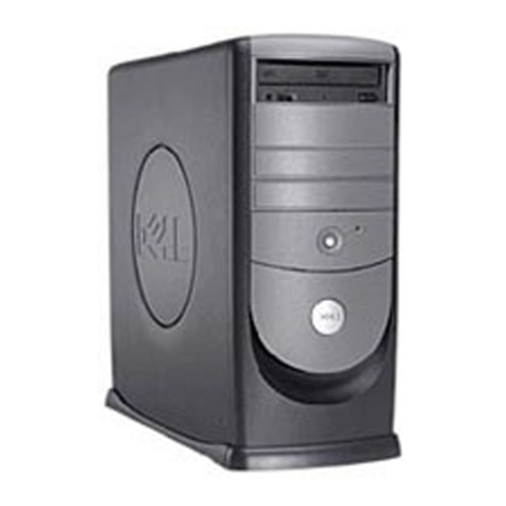
Dell™ Dimension™ 8250 Series
Technical Overview
Controls and Lights
Solving Problems
Advanced Troubleshooting
Technical Specifications
System Setup Program
Adding and Replacing Parts
Documentation
Hints, Notices, and Cautions
HINT:
A HINT indicates important information that helps you make better use of your computer.
NOTICE:
A NOTICE indicates either potential damage to hardware or loss of data and tells you how to avoid the problem.
CAUTION:
A CAUTION indicates a potential for property damage, personal injury, or death.
Abbreviations and Acronyms
For a complete list of abbreviations and acronyms, see the
If you purchased a Dell™ n Series computer, any references in this document to Microsoft® Windows® operating systems are not applicable.
Information in this document is subject to change without notice.
© 2002–2003 Dell Computer Corporation. All rights reserved.
Reproduction in any manner whatsoever without the written permission of Dell Computer Corporation is strictly forbidden.
Trademarks used in this text: Dell, the DELL logo, and Dimension are trademarks of Dell Computer Corporation; Intel, Pentium, and Celeron are registered trademarks of Intel
Corporation; Microsoft and Windows are registered trademarks of Microsoft Corporation.
Other trademarks and trade names may be used in this document to refer to either the entities claiming the marks and names or their products. Dell Computer Corporation
disclaims any proprietary interest in trademarks and trade names other than its own.
Model DHM
March 2003 Rev. A02
Tell Me How
help file.
Advertisement
Table of Contents

Related Manuals for Dell Dimension 8250 Series


Summary of Contents for Dell Dimension 8250 Series
-
Page 1: Abbreviations And Acronyms
Corporation; Microsoft and Windows are registered trademarks of Microsoft Corporation. Other trademarks and trade names may be used in this document to refer to either the entities claiming the marks and names or their products. Dell Computer Corporation disclaims any proprietary interest in trademarks and trade names other than its own. -
Page 2: Advanced Troubleshooting
"Resolving Software and Hardware Incompatibilities"). 4. If the problem persists, contact Dell. See your Owner's Manual for contact information. Memory modules are detected, but a Remove and reinstall all memory modules and CRIMMs. Ensure that all the connector tabs memory failure has occurred. -
Page 3: Beep Codes
One possible beep code (code 1-3-1) consists of one beep, a burst of three beeps, and then one beep. This beep code tells you that the computer encountered a memory problem. Reseating the memory modules may fix the beep code errors in the following table. If the problem persists, see "Contacting Dell" in your Owner's Manual for instructions on obtaining technical assistance. Code... -
Page 4: System Messages
C: Drive Failure The cache memory is not operating. See "Contacting Dell" in your Owner's Manual for instructions on obtaining Cache Memory Bad, Do technical assistance. Not Enable Cache An error is occurring on the timer on the system See "Contacting Dell"... -
Page 5: Identifying Drivers
Device Driver Rollback System Restore does not resolve the problem, then reinstall the driver from the Dell Dimension ResourceCD: 1. With the Windows desktop displayed, insert the ResourceCD into the CD or DVD drive. If this is your first time to use the ResourceCD, go to step 2. If not, go to step 5. -
Page 6: Using System Restore
Using System Restore The Microsoft® Windows® XP operating system provides System Restore to allow you to return your computer to an earlier operating state (without affecting data files) if changes to the hardware, software, or other system settings have left the computer in an undesirable operating state. See Windows Help for information on using System Restore. -
Page 7: Before You Reinstall
The Operating System CD provides options for reinstalling Windows XP. The options can overwrite files and possibly affect programs installed on your hard drive. Therefore, do not reinstall Windows XP unless instructed to do so by a Dell technical support representative. -
Page 8: Completing The Operating System Setup
NOTICE: When the computer restarts, the following message appears: Press any key to boot from the CD. Do not press any key when this message appears. 1. When the Regional and Language Options screen appears, select the settings for your location and click Next. 2. -
Page 9: Finding Information For Your Computer
Latest drivers for my computer Dell Support Website Answers to technical service and support questions The Dell Support website provides several online tools, including: Online discussions with other users and technical support Knowledge Base — Hints, tips, and online courses Documentation for my computer Customer Forum —... -
Page 10: Printed Documentation
Basic file management, such as finding, copying, deleting, and renaming files Tips on using your computer hardware Downloading the Tell Me How Help File 1. Right-click the following link to the file: Dell Dimension 8250 System Tell Me How (.chm) (563 KB). - Page 11 2. Click Save Target As in Microsoft Internet Explorer or Save Link As in Netscape Navigator, and specify a location on your hard drive. Viewing the Tell Me How Help File 1. Click the Start button on the Windows desktop, point to Programs, and then click Windows Explorer. 2.
-
Page 12: Adding And Replacing Parts
Back to Contents Page Adding and Replacing Parts Dell™ Dimension™ 8250 Series Turning Off the Computer Front-Panel Inserts Reattaching the Front Door and Hinge Arms Floppy Drive Opening the Computer Cover CD/DVD Drive Installing and Removing Cards Replacing the Microprocessor Adding Memory Removing the Front I/O Panel Adding or Replacing the AGP Card... - Page 13 CAUTION: Before you begin any of the procedures in this section, follow the safety instructions listed in your Owner's Manual. 1. Shut down the computer through the Start menu. 2. Disconnect the power cable from your computer. 3. Remove the front door, if it is attached. The front door snaps off of the two hinge arms.
-
Page 14: Opening The Computer Cover
CAUTION: To guard against electrical shock, always unplug your computer from the electrical outlet before opening the cover. Your Dell™ computer provides slots for up to four 32-bit, 33-MHz cards. Cards If you are installing or replacing a card, follow the procedures in the next section. If you are removing but not replacing a card, see "Removing a... - Page 15 4. Disconnect the computer power cable from the wall outlet, and then press the power button to ground the system board. Open the computer cover. 6. Press the lever on the card retention arm and raise the retention arm. 7. If you are installing a new card, remove the filler bracket to create a card-slot opening. Then continue with step 8.
-
Page 16: Removing A Card
8. If you are removing the card permanently, install a filler bracket in the empty card-slot opening. If you need a filler bracket, contact Dell. See your Owner's Manual for contact information. 9. Lower the retention arm and press it into place, securing the card(s) in the computer. -
Page 17: Removing A Memory Module
If you remove your original memory modules from the computer during a memory upgrade, keep them separate from any new modules that you may have, even if the new modules were purchased from Dell. Your original memory modules must be installed as a pair in either connectors RIMM1 and RIMM2 or RIMM3 and RIMM4. -
Page 18: Adding A Memory Module
1. Shut down the computer through the Start menu. NOTICE: To disconnect a network cable, first unplug the cable from your computer and then unplug it from the network wall jack. 2. Turn off any attached devices and disconnect them from their electrical outlets. 3. -
Page 19: Removing An Agp Card
Your Dell™ computer provides a connector for an AGP card. 1. Shut down the computer through the Start menu. NOTICE: To disconnect a network cable, first unplug the cable from your computer and then unplug it from the network wall jack. 2. Turn off any attached devices and disconnect them from their electrical outlets. -
Page 20: Removing A Hard Drive
Hard Drive CAUTION: Before you begin any of the procedures in this section, follow the steps in the safety instructions in your Owner's Manual. CAUTION: To guard against electrical shock, always unplug your computer from the electrical outlet before opening the cover. NOTICE: To avoid damage to the drive, do not set it on a hard surface. -
Page 21: Adding A Second Hard Drive
4. Install the hard drive into the computer by gently sliding the drive into place until you hear it securely click. NOTICE: Match the colored strip on the cable with pin 1 on the drive (pin 1 is marked as "1"). 5. - Page 22 8. Remove the two green plastic rails from the inside of the hard-drive bay by gently pulling the rails up and out of the bay. 9. Attach the rails to the hard drive using the two screws attached to the rails. Ensure that the rail tabs are positioned at the back of the hard drive.
-
Page 23: Front-Panel Inserts
7. If you purchased your floppy drive from Dell, attach the insert that you received in the floppy drive kit over the front of the drive bay. If you are installing a CD/DVD drive or floppy drive that was not purchased from Dell, reattach the empty insert frame over the front of the drive bay. -
Page 24: Removing A Floppy Drive
Floppy Drive CAUTION: Before you begin any of the procedures in this section, follow the steps in the safety instructions in your Owner's Manual. CAUTION: To guard against electrical shock, always unplug your computer from the electrical outlet before opening the cover. 1. -
Page 25: Removing A Cd/Dvd Drive
2. Gently slide the drive into place until the tabs securely click into position. 3. Attach the power and floppy-drive cables to the floppy drive. 4. If you are installing a new floppy drive rather than replacing a drive, remove the front-panel inserts. -
Page 26: Installing A Cd/Dvd Drive
2. Connect the new drive to the set of rails that are attached to the inside of the cover. If a set of rails is not attached inside the cover, contact Dell. See your Owner's Manual for contact information. -
Page 27: Replacing The Microprocessor
6. If you are installing a new CD/DVD drive rather than replacing a drive, remove the front-panel inserts. 7. If you are installing a drive that has its own controller card, install the controller card in a card slot. 8. Check all cable connections, and fold cables out of the way to provide airflow for the fan and cooling vents. Close the computer cover. -
Page 28: Installing The Microprocessor
NOTICE: Do not discard the original heat sink and securing clips unless you are installing a microprocessor upgrade kit from Dell. If you are not installing a microprocessor upgrade kit from Dell, reuse the original heat sink, blower, and securing clips when installing your new microprocessor. -
Page 29: Removing The Front I/O Panel
To connect a network cable, first plug the cable into the network wall jack and then plug it into the computer. If you are installing a microprocessor replacement kit from Dell, return the original heat sink assembly and microprocessor package to Dell in the same package in which your replacement kit was sent. -
Page 30: Removing The Power Supply
6. Remove all cables that are connected to the front I/O panel. 7. From inside the computer cover, remove the mounting screw that secures the front I/O panel to the computer. 8. Remove the front I/O panel from the computer. 9. -
Page 31: Replacing The Power Supply
Note the routing of the DC power cables underneath the tabs in the computer frame as you remove them from the system board and drives. It is important to route these cables properly when you replace them to prevent them from being pinched or crimped. 6. -
Page 32: Replacing The System Board
10. Place the system board assembly that you just removed next to the replacement system board. Replacing the System Board 1. Transfer components from the existing system board to the replacement system board: Remove the memory modules install them on the replacement board. CAUTION: The microprocessor package and heat-sink assembly can get hot. - Page 33 Back to Contents Page ...
-
Page 34: Solving Problems
If you have to repeatedly reset time and date information after turning on the computer, or if an incorrect time or date displays during start-up, replace the battery using the instructions in your Owner's Manual. If the battery still does not work properly, contact Dell. See your Owner's Manual for contact information. Drive Problems Floppy drive problems Ensure that Windows® recognizes the drive —... -
Page 35: E-Mail, Modem, And Internet Problems
NOTICE: Do not attempt to clean drive heads with a swab. You may accidentally misalign the heads, which can render the drive inoperable. Clean the drive — Use a commercially available cleaning kit. CD drive problems HINT: High-speed CD drive vibration is normal and may cause noise. This does not indicate a defect in the drive or the CD. Adjust the Windows volume control —... -
Page 36: Error Messages
Operating system not found — Contact Dell. See your Owner's Manual for contact information. The file being copied is too large for the destination drive — The file that you are trying to copy is too large to fit on the disk. Try copying the file to a blank disk or using a larger-capacity disk. -
Page 37: A Program Crashes Repeatedly
Go to support.dell.com for help with general usage, installation, and troubleshooting questions.The support website offers several different tools to help you, such as Dell Forum—a chat room where you can communicate with other Dell customers about their computers and gain access to technical support through e-mail. -
Page 38: Ieee 1394 Device Problems
If you have problems with a Dell-provided IEEE 1394 device — Contact Dell. See your Owner's Manual for contact information. If you have problems with a IEEE 1394 device not provided by Dell — Contact the IEEE 1394 device manufacturer. -
Page 39: Network Problems
Ensure that the front panel cable is securely connected to the system board. If the problem persists, contact Dell. See your Owner's Manual for contact information. If the power light is amber and green — The computer is receiving electrical power, but an internal power problem might exist. -
Page 40: Printer Problems
Multiple power strips connected to the same electrical outlet Printer Problems HINT: Dell does not cover the printer's warranty. If you need technical assistance for your printer, call the printer's manufacturer. See the printer documentation for the correct phone number. Check the printer documentation —... -
Page 41: Video And Monitor Problems
Test the electrical outlet — Ensure that the electrical outlet is working by testing it with another device, such as a lamp. Enable digital mode — Your speakers do not work if the CD drive is operating in analog mode. To enable digital mode: 1. -
Page 42: Technical Specifications
Back to Contents Page Technical Specifications Dell™ Dimension™ 8250 Series Microprocessor Drives Memory Connectors Computer Information Controls and Lights Video Power Audio Physical Expansion Bus Environmental Microprocessor Microprocessor type Intel® Pentium® 4 microprocessor that runs GHz internally and 400 MHz externally; or 2.26, 2.4, 2.53, 2.66, 2.8, or 3.06 GHz internally and 533 MHz... - Page 43 connectors four connector size 120 pins connector data width (maximum) 32 bits Drives Externally accessible two 3.5-inch bays two 5.25-inch bays Available devices ATA-66 or ATA-100 Ultra DMA hard drive, CD drive, Zip drive, DVD drive, CD-RW drive, DVD/CD-RW combo drive, and DVD+RW drive Internally accessible two bays for 1-inch–high hard drives...
- Page 44 Storage 0.5 G at 3 to 200 Hz at 1/2 octave/min Maximum shock: Operating bottom half-sine pulse with a change in velocity of 50.8 cm/sec (20 inches/sec) Storage 23-G faired-square wave with a velocity change of 508 cm/sec (200 inches/sec) Altitude: Operating –15.2 to 3048 m (–50 to 10,000 ft)
-
Page 45: System Setup Program
Back to Contents Page System Setup Program Dell™ Dimension™ 8250 Series Standard Settings Hyper-Threading Viewing Settings Clearing Forgotten Passwords Standard Settings The system setup program contains the standard settings for your computer. NOTICE: Unless you are an expert computer user, do not change the settings for this program. Certain changes might make your computer work incorrectly. -
Page 46: Viewing Settings
3. In the Device Manager window, click the plus (+) sign next to the processor type. If Hyper-Threading is enabled, the processor is listed twice. For more information on Hyper-Threading, search the Knowledge Base on the Dell Support website at support.dell.com. -
Page 47: Clearing Forgotten Passwords
AC Power Recovery Enables AC power recovery to occur. The default is Off. Fast Boot Turns the fast boot option on and off. The default is On. Suspend Mode Displays the suspend state used by the computer. The default is S3. System Event Log Displays the system event log when <Enter>... - Page 48 Shut down the computer. NOTICE: To disconnect a network cable, first unplug the cable from your computer, and then unplug it from the network wall jack. 8. Turn off any attached devices and disconnect them from their electrical outlets. 9. Disconnect the computer power cable from the wall outlet, and then press the power button to ground the system board. Open the computer cover.
-
Page 49: Technical Overview
Looking Inside Your Computer System Board Power Supply DC Power Connectors IDE Interface Cable Connections for Dell-Installed Drives Placement of Dell-Installed Cards Looking Inside Your Computer HINT: The AGP card is removed from the following illustration to provide a better view of the inside of your computer. -
Page 50: Power Supply Dc Connector Pin Assignments
Power Supply The 250-W power supply can operate from an AC power source of 115 VAC at 60 Hz or 230 VAC at 50 Hz. The power supply provides the DC operating voltages and currents listed in the following table. Output Voltage Minimum Current (A) Maximum Current (A) -
Page 51: Dc Power Connector P1
DC Power Connector P1 Pin Number Signal name Wire +3.3 VDC Orange +3.3 VDC Orange Black +5 VDC Black +5 VDC Black Gray +5 VFP Purple +12 VDC Yellow +3.3 VDC* Orange –12 VDC Blue Black PS ON Green Black Black Black +5 VCD... -
Page 52: Dc Power Connector P7
DC Power Connector P7 Pin Number Signal Name Wire +5 VCD Black Black +12 VDC Yellow IDE Interface Cable Connections for Dell-Installed Drives IDE Channel Connector Location Dell- Installed Drive Primary IDE master End connector on PRI IDE connector cable Hard... - Page 53 PCI4 connector 1394 FireWire Back to Contents Page ...
-
Page 54: Controls And Lights
To avoid losing data, do not use the power button to turn off the computer. Instead, perform a Windows shutdown. service tag The tag is used to identify your computer when you access the Dell Support website or call technical support. 10 headphone connector Attach headphones. - Page 55 Attach the UTP cable to an RJ45 jack wall plate or to an RJ45 port on a UTP concentrator or hub and press the other end of the UTP cable into the network adapter connector until the cable snaps securely into place. Dell recommends the use of Category 5 wiring and connectors for our customers' networks. line-in connector Use the blue line-in connector (available on computers with integrated sound) to attach a record/playback device such as a cassette player, CD player, or VCR.
Need help?
Do you have a question about the Dimension 8250 Series and is the answer not in the manual?
Questions and answers