Advertisement
NOTE:
Please read all instructions
carefully before using this
product
Table of Contents
Safety Notice
Hardware Identifier
Assembly Instruction
Parts List
Resistance Chart
Warranty
Ordering Parts
Model
WM-1501
Retain This
Manual for
Reference
10-24-05
OWNER'S
MANUAL
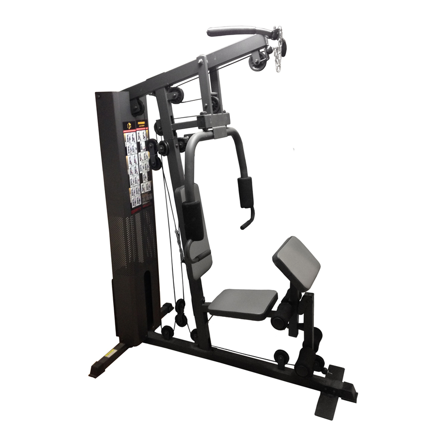
MARCY HOME GYM
14777 DON JULIAN RD., CITY OF INDUSTRY, CA 91746
Tel: (800) 999-8899 Fax: (626) 961-9966
www.impex-fitness.com
info@impex-fitness.com
WM-1501
IMPEX INC.
Advertisement
Table of Contents

Subscribe to Our Youtube Channel
Related Manuals for Impex WM-1501


Summary of Contents for Impex WM-1501
- Page 1 NOTE: Please read all instructions carefully before using this product Table of Contents MARCY HOME GYM Safety Notice WM-1501 Hardware Identifier Assembly Instruction Parts List Resistance Chart Warranty Ordering Parts Model WM-1501 Retain This Manual for Reference 10-24-05 IMPEX INC.
-
Page 2: Table Of Contents
ORDERING PARTS..................………… 20 BEFORE YOU BEGIN Thank you for selecting the MARCY WM-1501 HOME GYM by IMPEX INC. For your safety and benefit, read this manual carefully before using the machine. As a manufacturer, we are committed to provide you complete customer satisfaction. -
Page 3: Important Safety Notices
IMPORTANT SAFETY NOTICE PRECAUTIONS This exercise machine is built for optimum safety. However, certain precautions apply whenever you operate a piece of exercise equipment. Be sure to read the entire manual before you assemble or operate your machine. In particular, note the following safety precautions: 1. - Page 4 WARNING LABEL REPLACEMENT The warning labels shown here have been placed on Rear Base and Upper Frame. If the labels are missing or illegible call customer service at 1-800-888-8899 for replacement. Apply the labels in the location shown...
-
Page 5: Hardware Pack
HARDWARE PACK... - Page 6 HARDWARE PACK...
- Page 7 HARDWARE PACK...
-
Page 8: Assembly Instructions
ASSEMBLY INSTRUCTION Tools Required Assembling the Machine: Two Adjustable Wrenches, two Allen Wrenches, and one Philips Screwdriver. NOTE: It is strongly recommended this machine to be assembled by two or more people to avoid possible injury. STEP 1 (See Diagram 1) A.) Attach the Front Vertical Frame (#3) to the Main Base Frame (#8). - Page 9 STEP 2 (See Diagram 2) A.) Slide the 9 Weight Plates (#29) onto the Guide Rods (#20). Align the holes of the Weight Plates. Insert the Selector Rod (#13) through the center hole. Use a L-shaped Pin (#30) to select the number of plates. B.) Slide the Selector Stem (#28) onto the Guide Rods.
- Page 10 STEP 3 (See Diagram 3) A.) Attach the Front Press Base (#11) to the Upper Frame (#4). Secure it with one Long Axle (#43), two Ø ¾” Washers (#80), and two M10 Aircraft Nuts (#82). B.) Attach the Right Butterfly (#6) to the Front Press Base. Secure it with one M6 x 1 5/8” Hex Bolt (#75), Lock Ring (#37), and M6 Aircraft Nut (#83).
- Page 11 STEP 4 (See Diagram 4) A.) Attach the Main Seat Support (#1) to the Front Vertical Frame (#3). Secure it with two M10 x 3 ½” Carriage Bolts (#76), one 4 ¾” x 2” Bracket (#24), two ¾” Washers (#80), and two M10 Aircraft Nuts (#82).
- Page 12 CABLE LOOP DIAGRAM...
- Page 13 STEP 5 (See Diagram 5 & Cable Loop Diagram) A.) Attach the 131” Upper Cable (#31) to the opening at the front of the Upper Frame (#4). Note: The Ball Stopper on the cable should be underneath the Frame. B.) Attach a Pulley (#60) to the open bracket. Secure it with one M10 x 1 ¾” Allen Bolt (#69), two Ø...
- Page 14 DIAGRAM 5...
- Page 15 STEP 6 (See Diagram 6 & Cable Loop Diagram) A.) Attach one end of the 119” Butterfly Cable (#33) to the hook on the Right Butterfly (#6). B.) Draw the Cable to the right Swivel Pulley Bracket (#18). C.) Attach a Pulley to the bracket. Secure it with one M10 x 1 ¾” Allen Bolt (#69), two Ø ¾” Washers (#80), and one M10 Aircraft Nut (#82).
- Page 16 STEP 7 (See Diagram 7 & Cable Loop Diagram) A.) Attach the 128” Lower Cable (#32) to the open bracket on the bottom of the Leg Developer (#7). B.) Attach a Pulley to the bracket. Secure it with one M10 x 1 ¾” Allen Bolt (#69), two Ø ¾”...
- Page 17 DIAGRAM 7...
- Page 18 STEP 8 (See Diagram 8) A.) Attach a Short Chain (#46) to the Upper Cable (#31) by using a C-clip (#50). Attach the Lat Bar (#14) to the Chain by using another C-clip. Adjust the length of the Chain to obtain desired Lat Bar exercise. B.) Attach a Long Chain (#45) to the Lower Cable (#32) by using a C-clip (#50).
-
Page 19: Parts List
PARTS LIST KEY NO. DESCRIPTION Q’ty Front Base Frame End Cap Main Seat Support Rear Base Frame End Cap Rear Base Frame 2” x 1” End Cap Front Vertical Frame 2 ¾” x 2” End Cap Upper Frame 2” Square End Cap Left Butterfly Ø... -
Page 21: Warranty
IMPEX INC. LIMITED WARRANTY IMPEX Inc. ("IMPEX") warrants this product to be free from defects in workmanship and material, under normal use and service conditions, for a period of two years on the Frame from the date of purchase. This warranty extends only to the original purchaser. IMPEX's obligation under this Warranty is limited to replacing or repairing, at IMPEX's option.
Need help?
Do you have a question about the WM-1501 and is the answer not in the manual?
Questions and answers
My wm1501 is very noisy (squeaky). How can I lubricate.
To lubricate the Impex WM-1501 and reduce noise, apply WD-40 or light oil to the moving parts periodically.
This answer is automatically generated