Advertisement
Quick Links
NOTE:
Please read all instructions
carefully before using this
product
Table of Contents
Safety Notice
Hardware Identifier
Assembly Instruction
Parts List
Resistance Chart
Warranty
Ordering Parts
Model
WM 1403
Retain This
Manual for
Reference
06-19-02
OWNER'S
MANUAL
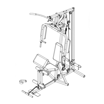
POWERHOUSE HOME GYM
IMPEX FITNESS PRODUCTS
14777 DON JULIAN RD., CITY OF INDUSTRY, CA 91746
Tel: (800) 999-8899 Fax: (626) 961-9966
www.impex-fitness.com
info@impex-fitness.com
WM 1403
Advertisement

Subscribe to Our Youtube Channel
Related Manuals for Impex WM 1403


Summary of Contents for Impex WM 1403
- Page 1 NOTE: Please read all instructions carefully before using this product Table of Contents Safety Notice POWERHOUSE HOME GYM Hardware Identifier WM 1403 Assembly Instruction Parts List Resistance Chart Warranty Ordering Parts Model WM 1403 Retain This Manual for Reference 06-19-02...
-
Page 2: Table Of Contents
ORDERING PARTS..................………… 21 BEFORE YOU BEGIN Thank you for selecting the POWERHOUSE WM1403 HOME GYM by IMPEX FITNESS PRODUCTS. For your safety and benefit, read this manual carefully before using the machine. As a manufacturer, we are committed to provide you complete customer satisfaction. -
Page 3: Important Safety Notice
PHYSICIAN. THIS IS ESPECIALLY IMPORTANT FOR INDIVIDUALS OVER THE AGE OF 35 OR PERSONS WITH PRE-EXISTING HEALTH PROBLEMS. READ ALL INSTRUCTIONS BEFORE USING ANY FITNESS EQUIPMENT. IMPEX INC. ASSUMES NO RESPONSIBILITY FOR PERSONAL INJURY OR PROPERTY DAMAGE SUSTAINED BY OR THROUGH THE USE OF THIS PRODUCT. -
Page 5: Assembly Instructions
ASSEMBLY INSTRUCTION Tools Required Assembling the Machine: Two Adjustable Wrenches, two Allen Wrenches, and one Flat Head Screwdriver. NOTE: It is strongly recommended this machine to be assembled by two or more people to avoid possible injury. STEP 1 (See Diagram 1) A.) Connect the Main Base Frame (#6) and Rear Lower Vertical Beam (#81) to the Rear Stabilizer (#3). - Page 6 STEP 2 (See Diagram 2) A.) Attach the Front Upper Vertical Beam (#5) to the Front Lower Vertical Beam (#82). Secure it with two M10 x 2 ½” Carriage Bolts (#42), ∅ ¾” Washers (#53), and M10 Aircraft Nuts (#55). DIAGRAM 2...
- Page 7 STEP 3 (See Diagram 3) A.) Attach the Front Lower Vertical Beam (#82), both Left and Right Storage Posts (#15) & (#16) to the Main Base Frame (#6). Secure them together with two M10 x 3” Carriage Bolts (#73), ∅ ¾” Washers (#53) and M10 Aircraft Nuts (#55). Do not tighten the nuts and bolts yet. B.) Secure the upper portion of Left &...
- Page 8 STEP 4 (See Diagram 4) A.) Slide the Weight Holder (#2) onto the Rear Vertical Beam (#1) from the top. B.) Attach the rear end of Upper Frame (#4) to the Rear Upper Vertical Beam (#1). Secure the upper hole with a Small Bracket (#20), M10 x 2 3/8” Allen Bolt (#46), and ∅ ¾” Washer (#53).
- Page 9 STEP 5 (See Diagram 5) A.) Attach the Front Press Base (#12) to the Upper Frame (#4). Secure it with one 5 7/8” Axle (#60), two ∅ 1” Axle Washers (#64), and two M10 Aircraft Nuts (#55). Do not over tighten the nuts.
- Page 10 STEP 6 (See Diagram 6) A.) Attach a Rubber Bumper (#38) to the Leg Developer (#11). Secure it with one M6 x 5/8” Philips Screw (#41). Attach the Leg Developer to the bracket on the Main Seat Support (#7). Secure it with one M10 x 3” Allen Bolt (#44), two ∅ ¾” Washers (#53), and one M10 Aircraft Nut (#55).
- Page 11 STEP 7 (See Diagram 7) A.) Insert the axle on the Right Butterfly Arm (#14) through the right pivot hole on the Front Press Base (#12). Slide a ∅ 1 ½” Washer (#54) and Ring Cap (#68) onto the axle. Secure the Cap with a M6 x 1 5/8”...
- Page 12 Cable Loop Diagram...
- Page 13 STEP 8 (See Cable Loop Diagram & Diagram 8) A.) Attach the 129.9” Upper Cable (#31) to the open bracket in the front of Upper Frame (#4). Attach a Pulley (#28) to the open bracket. Secure it with one M10 x 1 ¾” Allen Bolt (#45), two ∅...
- Page 14 Diagram 8...
- Page 15 STEP 9 (See Cable Loop Diagram & Diagram 9) A.) Attach one end of the 116” Butterfly Cable (#29) to the Hook on the Right Butterfly Arm (#14). Pull the Cable to the Butterfly Pulley Bracket (#10). Attach a Pulley (#28) to the Bracket (#10).
- Page 16 STEP 10 (See Cable Loop Diagram & Diagram 10) A.) Insert the 110.2” Lower Cable (#30) through the opening on bottom of the Leg Developer (#11). Attach a Pulley (#28) to the opening. Secure it with one M10 x 2 3/8” Allen Bolt (#46), two ∅ 7/8” Pulley Bushings (#51), and one M10 Aircraft Nut (#55).
- Page 17 DIAGRAM 10 STEP 11 (See Diagram 11)
- Page 18 A.) Attach a Butterfly Arm Pad (#24) to the Right Butterfly Arm (#14). Secure it with two M8 x 2” Allen Bolts (#74) and ∅ 5/8” Washers (#52). Repeat the same procedure to install the other side. B.) Attach the Backrest Board (#23) to the Front Upper Vertical Frame (#5). Secure it with two M8 x 2 1/8”...
- Page 19 STEP 12 (See Diagram 12) A.) Insert two Foam Roll Tubes (#27) halfway through the holes on the Main Seat Support (#7) and Leg Developer (#11). Push four Foam Rolls (#26) onto the tubes. B.) Connect the Arm Curl Handle (#70) to the Lower Cable with two C-clips (#57) and one Long Chain (#79).
-
Page 20: Parts List
PARTS LIST KEY NO. DESCRIPTION Q’ty ∅ 7/8” Pulley Bushing Rear Upper Vertical Beam ∅ 5/8” Washer Weight Holder ∅ ¾” Washer Rear Stabilizer ∅ 1 ½” Washer Upper Frame M10 Aircraft Nut Front Upper Vertical Beam M6 Aircraft Nut Main Base Frame C-clip Main Seat Support... -
Page 21: Weight Resistance Chart
WEIGHT RESISTANCE CHART The following chart shows the approximate weight resistance ratio at each station. Weight resistance shows for the butterfly station is for each butterfly arm. The actual resistance at each station may vary due to friction and differences in each individual plate. Weight Front Butterfly... -
Page 22: Warranty
IMPEX Customer Service Department at 1-800-999-8899. All freights on products returned to IMPEX must be prepaid by the customer. This warranty does not extend to any product or damage to a product caused by or attributable to freight damage, abuse, misuse, improper or abnormal usage or repairs not provided by an IMPEX authorized service center or for products used for commercial or rental purposes.
Need help?
Do you have a question about the WM 1403 and is the answer not in the manual?
Questions and answers