Table of Contents
Advertisement
Quick Links
Advertisement
Table of Contents

Related Manuals for AOpen DEX4500 series


Summary of Contents for AOpen DEX4500 series
- Page 1 Assembly Guide for DEX4500 series V2.0 2008/12/17...
-
Page 2: Table Of Contents
Index 1. Outlook …………..……………………………………………………..2 2. Install Key components ( Except Mini card module installation)…….4 3. Install Key components ( Including Mini card module installation)...16 4. Connector & PINs definitions……………………..…………………..39 5. Appendix 1 Packing List……………………………………………….41 6. Appendix 2 Table of Screw and Torque…………….……………….42 7. -
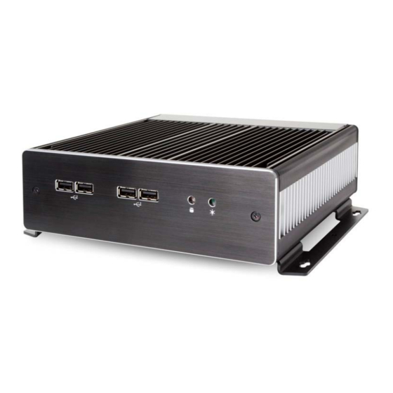
Page 3: Outlook
1. Outlook Front IO HDD Power... - Page 4 Rear IO Antenna Hole TV-Tuner WLAN COM 1 Power SW HDMI USB Audio input e-SATA...
-
Page 5: Install Key Components (Except Mini Card Module Installation)
2. Install Key components (Except Mini card module installation) 2-1. 2-2. Loosen 2 pcs of front panel screw (FPH M3 Loosen 4 pcs of Top cover screw (FPH M3 screw) by the screw driver and remove it. screw) by the screw driver and remove it. Unscrew 2 x FPH M3 screw Unscrew 4 x M3 screw... - Page 6 2-3. You will see the kernel of Digital Engine. Heatsink Cooler DIMM Heatsink Heatsink...
- Page 7 2-4 Install Memory 2-4-1. 2-4-2. Loosen 2 pcs of DIMM heatsink screw (FPH Insert the memory on the upper socket as this M3 screw) by the screw driver and remove it. angle. Upper socket Unscrew Insert DIMM as this angle 30°...
- Page 8 2-4-3. 2-4-4. Then press the DIMM as flat on the Take off the protect Mylar of thermal pad of Motherboard, and you will hear the click voice. DIMM heatsink and place it back to ICH heatsink. Make sure it clicks...
- Page 9 2-4-5. Screw it tightly with 2 pcs of FPH M3 screws by the screw driver (Screwdriver torque : 3.0 ±0.5 kgf. cm ) Screw...
- Page 10 2-5 Install CPU 2-5-1. 2-5-2. Loosen 4 pcs of CPU cooler screw by the Unlock the CPU socket screw screw driver and remove it. Counterclockwise Unscrew...
- Page 11 2-5-3 2-5-4. Put the CPU into the socket, and check the Lock the CPU socket screw direction. clockwise...
- Page 12 2-5-5. 2-5-6. Place the CPU cooler back and follow up the Place the Top Cover back and screw it tightl sequence to screw it tightly with 4 pcs of FPH M3 screws by the screw (Screwdriver torque : 3.0 ±0.5 kgf. cm ) river.
- Page 13 2-6 Install HDD 2-6-1 2-6-2 Turn over the system and loosen 4 pcs of Bottom emove the Bottom Cover. over screw ( FPH M3 screw ) by the screw driver and remove it HDD Bracket Power & SATA cable...
- Page 14 2-6-3. 2-6-4. Connect HDD to SATA and Power cable, then Tighten HDD with 4pcs of FPH M3 screw put HDD on the HDD bracket. (on both flanks) (Screwdriver torque : 2.5 ±0.1 kgf. cm )
- Page 15 2-6-5. 2-6-6. ake off the protect Mylar of thermal pad on Place Bo ttom Cover back and screw it tightly ottom Cover before place it back. with 4 pcs of FPH M3 screws by the scre river. (Screwdriver torque : 3.0 ±0.5 kgf. cm )
- Page 16 2-7. Place Front Panel back and screw it tightly with 2 cs of FPH M3 screws by the screw driver. Screwdriver torque : 3.0 ±0.5 kgf. cm ) FPH M3xL5 Screw...
-
Page 17: Install Key Components (Including Mini Card Module Installation)
3. Install Key components (Including Mini card module installation) 3-1. 3-2. Loosen 2 pcs of front panel screw (FPH M3 Loosen 4 pcs of Top cover screw (FPH M3 screw) by the screw driver and remove it. screw) by the screw driver and remove it. Unscrew 2 x FPH M3 screw Unscrew 4 x M3 screw... - Page 18 3-3. You will see the kernel of Digital Engine. Top Cover - Back Heat sink cooler DIMM Heat sink Heat sink DIMM MCH Heat Heat sink sink-AL Cover - AL Cover...
- Page 19 3-4 Install WLAN & TV-Tuner Module . 3-4-1. 3-4-2. Loosen 2 pcs of DIMM heat sink – AL cover Loosen 1 pcs of Top-Back cover screw (FPH M3 screw (FPH M3 screw) by the screw driver screw) by the screw driver and remove it. and remove it.
- Page 20 3-4-3. 3-4-4. Loosen 2 pcs of MCH heat sink – AL cover Loosen 1 pcs of Top-Back Cover screw (FPH M3 screw (FPH M3 screw) by the screw driver screw) by the screw driver and remove it. and remove it. Unscrew Unscrew...
- Page 21 3-4-5. 3-4-6. Remove Top -Back Cover. Loosen 4 pcs of DIMM & ICH heat sink screw (FPH M3 screw) by the screw driver and remove Unscrew...
- Page 22 3-4-7. 3-4-8. WLAN Mini card module List. Loosen 1 pcs of Mini Card screw by the screw driver and remove it. Unscrew...
- Page 23 3-4-9. 3-4-10. Install WLAN Mini card and fix 1 pcs of Mini Remove the metal cover of the WLAN antenna Card screw by the screw driver. hole by the screw driver. (Screwdriver torque : 1.0 ±0.1 kgf. cm ) WLAN Antenna Hole Screw...
- Page 24 3-4-11. 3-4-12. Insert WLAN Antenna into the hole. Buckle the mini card with the Antenna wire Tighten the nut by the screw sleeve. (CON1) and arrange the wire according the (The diameter of the nut is 8mm). photo. . Buckle Arrange the wire Screw...
- Page 25 3-4-13. 3-4-14. TV-Tuner Mini card module List. Loosen 1 pcs of Mini Card screw by the screw driver and remove it. Unscrew...
- Page 26 3-4-15. 3-4-16. Install TV-Tuner Mini card and fix 1 pcs of Remove the metal cover of the TV-Tuner antenna Mini Card screw by the screw driver. hole by the screw driver. (Screwdriver torque : 1.0 ±0.1 kgf. cm ) Screw TV-Tuner Antenna Hole...
- Page 27 3-4-17. 3-4-18. Insert TV-Tuner Antenna into the hole. Buckle the mini card with the Antenna wire and Tighten the nut by the screw sleeve. arrange the wire according the photo. . (The diameter of the nut is 8mm). Buckle Arrange the wire Screw...
- Page 28 3-4-19. 3-4-20. Install ICH heat sink vertically and tighten 2 Install Top -Back Cover. pcs of screw (FPH M3 screw) by the screw driver. (Screwdriver torque : 3.0 ±0.5 kgf. cm ) Screw...
- Page 29 3-4-21. 3-4-22. Tighten 2 pcs of Top -Back Cover screw Tighten 4 pcs of DIMM & MCH heat sink – AL (FPH M3 screw) by the screw driver. covers screw (FPH M3 screw) by the screw (Screwdriver torque : 3.0 ±0.5 kgf. cm ) driver.
- Page 30 3-4-23. 3-4-24. Note that DIMM & MCH heat sink – AL cover Note that detach ICH heat sink after DIMM heat have to be installed in the correct position to sink – AL cover has already to be detached to avoid influence the thermal efficiency.
- Page 31 3-5-1. 3-5-2. Insert the memory on the upper socket as Press the DIMM as flat on the Motherboard, and this angle. you will hear the click voice. Upper socket Insert DIMM as this angle 30° Make sure it clicks...
- Page 32 3-5-3. 3-5-4. Take off the protect Mylar of thermal pad of Screw it tightly with 2 pcs of FPH M3 screws by DIMM heatsink and place it back to ICH the screw driver (Screwdriver torque : 3.0 ±0.5 kgf. cm ) heatsink.
- Page 33 3-6 Install CPU 3-6-1. 3-6-2. Loosen 4 pcs of CPU cooler screw by the Unlock the CPU socket screw. screw driver and remove it. Counterclockwise. Unscrew...
- Page 34 3-6-3 3-6-4. Put the CPU into the socket, and check the Lock the CPU socket screw direction. lockwise...
- Page 35 3-6-5. 3-6-6. Place the CPU cooler back a nd follow up the Place the Top Cover back and screw it tightl sequence to screw it tightly with 4 pc s of FPH M3 screws by the screw (Screwdriver torque : 3.0 ±0.5 kgf. cm ) driver.
- Page 36 3-7 Install HDD 3-7-1 3-7-2 Turn over the system and loosen 4 pcs of emove Bottom Cover. ottom cover screw (FPH M3 screw) by the screw driver and remove it. HDD Bracket Power & SATA cable...
- Page 37 3-7-3. 3-7-4. Connect HDD to SATA and Power cable, then Tighten HDD with 4pcs of FPH M3 screw (on put HDD to HDD bracket both flanks) (Screwdriver torque : 2.5 ±0.1 kgf. cm )
- Page 38 3-7-5. 3-7-6. ake off the protect Mylar of thermal pad on Place Bo ttom Cover back and screw it tightly ottom Cover before place it back. with 4 pcs of FPH M3 screws by the scre driver. (Screwdriver torque : 3.0 ±0.5 kgf. cm )
- Page 39 3-8. Place Front Panel back and screw it tightly with pcs of FPH M3 screws by the screw driver. rewdriver torque : 3.0 ± 0.5 kgf. cm ) FPH M3xL5 Screw...
-
Page 40: Connector & Pins Definitions
4. Connector & PINs definitions 4-1. COM1 connector Front Panel connector... - Page 41 4-3. 4-4. USB 2.0 connector Front Audio connector...
-
Page 42: Appendix 1 Packing List
Appendix 1 Packing List 1 x DEX4500 system 1 x Easy Assembly Guide 1 x Driver CD 1 x 90W Adapter and Power Cord 4 x M3 - L5 screws 2 x Cable clamp 1 x DVI to VGA adapter □... -
Page 43: Appendix 2 Table Of Screw And Torque
Appendix 2 Table of Screw and Torque Screw Photo Position Q’ty Screw spec. Torque Screw driver spec. ♁ FPH M3- L5 3.0±0. 5 Phillips #2 kgf-cm... -
Page 44: Appendix 3 Watch Dog Timer Configuration
Appendix 3 Watch Dog Timer Configuration The WDT is used to generate a variety of output signals after a user programmable count. The WDT is suitable for use in the prevention of system lock-up, such as when software becomes trapped in a deadlock. Under these sort of circumstances, the timer will count to zero and the selected outputs will be driven. - Page 45 CODE FLOW-CHART 1. Initial Watchdog Pin (1)set -> Logical Device: Global CR: 0x2D Bit: 0 = 0 WDTO. (2)set -> Logical Device: 0x09 CR: 0X30 Start Bit:3 = 1 activate GPIO5 CR: 0xE0, 0xE1, 0xE2 Bit: 6, Bit: 7, Bit: 6 = 0 GPIO port is programmed as an output port.
- Page 46 1. Set Mode (1)set -> Logical Device: 0x08 CR: 0xF5 Set Min/Sec Mode Bit: 3 = 0 By second = 1 By minute Start Timer 1. Set Mode (1)set -> Logical Device: 0x08 CR: 0xF6 Bit: 7~0 = 0x01 Time- out occur after 1 second/minute = 0xFF Time- out occur after 255 second/minute...
-
Page 47: Sample Code
SAMPLE CODE: This code and information is provided "as is" without warranty of any kind, either expressed or implied, including but not limited to the implied warranties of merchantability and/or fitness for a particular purpose. This program just for MB with Winbond W83267DHG LPC I/O 1. - Page 48 2. Stop Timer 3. Set Min/Sec Mode outportb(0x2E,0x87); outportb(0x2E,0x87); outportb(0x2E,0x87); outportb(0x2E,0x87); outportb(0x2E,0x87); outportb(0x2E,0x87); outportb(0x2E,0x07); outportb(0x2E,0x07); outportb(0x2E,0x07); outportb(0x2F,0x08); outportb(0x2F,0x08); outportb(0x2F,0x08); outportb(0x2E,0xF5); outportb(0x2E,0xF6); outportb(0x2E,0xF7); outportb(0x2F,byBit); outportb(0x2F,byBit); outportb(0x2F,byBit); outportb(0x2E,0xAA); outportb(0x2E,0xAA); outportb(0x2E,0xAA); 4. Start Timer outportb(0x2E,0x87); outportb(0x2E,0x87); outportb(0x2E,0x87); outportb(0x2E,0x87); outportb(0x2E,0x07); outportb(0x2E,0x07); outportb(0x2F,0x08); outportb(0x2F,0x08); outportb(0x2E,0x30); outportb(0x2E,0xF6);...
-
Page 49: Appendix 4 Outline Drawing
Appendix 4 Outline Drawing... - Page 50 P/N:49.DE201.0010 S/N:088-099-118...
Need help?
Do you have a question about the DEX4500 series and is the answer not in the manual?
Questions and answers