
Related Manuals for Northern Lights Lugger ONL753W2


Summary of Contents for Northern Lights Lugger ONL753W2
- Page 1 ONL753W2 For Models: NL753W and NL753W2 OPERATOR’S MANUAL Marine Generators | Marine Diesel Engines | Land-Based Generators...
- Page 2 4420 14th Avenue N.W. Seattle, WA 98107 Tel: (206) 789-3880 Fax: (206) 782-5455 Copyright ©2009 Northern Lights, Inc. All rights reserved. Northern Lights™, and the Northern Lights logo are trademarks of Northern Lights, Inc. Printed in U.S.A. PART NO.: ONL753W2 10/09...
-
Page 3: Table Of Contents
This publication is the property of Northern Lights, Inc. It may not be reproduced in whole or in part without the written permission of Northern Lights, Inc. © Northern Lights, Inc. All rights reserved. Litho U.S.A. Publication number ONL753W2 10/09... -
Page 4: Introduction
Bore Cylinders generator set 75 mm Northern Lights industrial generator set with a Northern Lights industrial generator set with a 753 NL753W NL753W2 753 engine, PXK2 series generator end, and AVR. engine, PXK2 series generator end, AVR, Tier II. Serial Numbers Your set has three serial numbers: ... -
Page 5: Warranty
Warranty A warranty registration certifi cate is supplied NOTE: If the warranty is to apply, the servicing with your set. It entitles the original purchaser of instructions outlined in this manual must be our equipment to a warranty covering material followed. -
Page 6: Industrial Generator
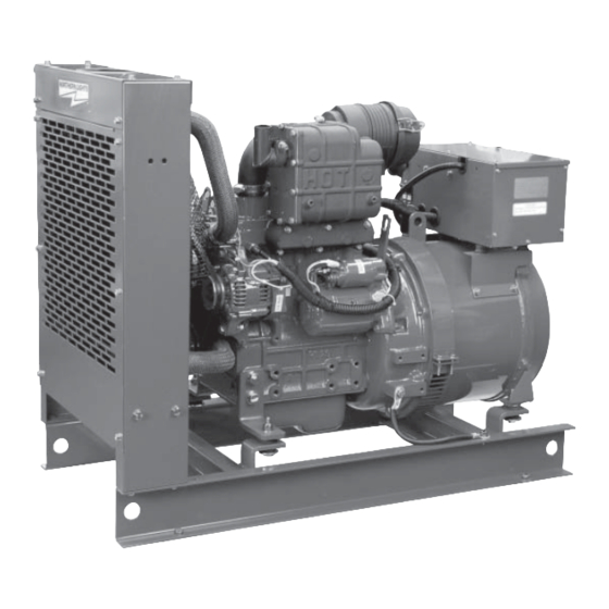
Industrial Generator Component Locations Figures 2-A and B: NL753W 1. Junction Box 8. Fuel Inlet & Return 2. Air Filter 9. Block Water Drain 3. Crankcase Vent 10. Oil Filter 4. Lube Oil Fill 11. Fuel Lift Pump 15. Exhaust Outlet 18. -
Page 7: Control Panel
Control Panel Figure 3: Series 1-B Generator Control Panel 1. SHUTDOWN BYPASS-PREHEAT SWITCH There are two functions built into this switch: preheating the engine and bypassing the engine safety shutdown circuit, enabling a quicker start. Hold the switch in the ON position for approximately 10 to 20 seconds before starting a cold engine. -
Page 8: Operating Procedures
Operating Procedures STARTING BREAK-IN PERIOD 1. Hold the Shutdown Bypass-Preheat switch in the ON 1. The fi rst 100 hours on a new or reconditioned position for 10 to 20 seconds before starting a cold engine are critical to its life and performance. engine. -
Page 9: Shutdowns And Alarms
Operating Procedures SPARE PARTS SHUTDOWNS AND ALARMS 1. Northern Lights, Inc. recommends that you keep the 1. Generator sets have shutdown systems to stop the following spare parts on hand for fi eld service. The engine in the event of high water temperature or low parts are available from your local Northern Lights oil pressure. -
Page 10: Servicing Schedule Chart
Servicing Schedule Chart The Servicing Schedule Chart below shows the service schedule required for proper maintenance of your generator set. More detailed coverage of each Service Point (SP) is listed on the page noted in the ‘page’ column. DAILY: EVERY 250 HOURS: SP2/3 Change engine oil and fi... - Page 11 Service Record Notes ONL753W2 10/09...
-
Page 12: Servicing
Servicing SP2. OIL CHANGES LUBRICATION - GENERAL 1. The set is delivered with special break-in oil. 1. Use only clean, high quality lubricants stored in Change the engine oil and oil fi lter after 50 hours clean containers in a protected area. of operation. -
Page 13: Air Filter
Servicing SP4. AIR CLEANER 1. Inspect air cleaner every 250 hours. In dusty condi- tions, check more often. 2. Industrial sets: the element cannot be cleaned. Replace it when necessary. Part numbers are: NL753W & W2 – #24-27301 4. NOTE: Make absolutely sure no impurities enter the engine while changing the element. -
Page 14: Fuels - General
Servicing FUELS - GENERAL SP7-9. FUEL FILTERS 1. Use only clean, high quality fuels of the following 1. Your generator set should have a primary fuel fi lter specifi cations, as defi ned by ASTM designation installed. We recommend the Racor brand of fuel D975 for diesel fuels: fi... -
Page 15: Bleeding The Fuel System
Servicing SP10. BLEEDING THE FUEL SYSTEM CAUTION: Escaping diesel fuel under pressure can penetrate skin causing serious personal injury. Before disconnecting lines be sure to relieve all pressure. Before applying pressure, be sure all connections are tight and lines, pipes and hoses aren't damaged. - Page 16 Servicing Figure 7: Remove delivery line fl are nuts. Figure 11: Unscrew injector. Figure 8: Remove delivery lines. Figure 12: Remove and replace copper sealing washer. Figure 9: Remove return line nuts. Figure 13: Reinstall injector. Torque to proper tightness. Figure 10: Remove return line.
-
Page 17: Injector Service
1. Since operating conditions may vary considerably, it 1. Injectors should be checked every 1000 hours or as needed. Check should be made by a Northern Lights is diffi cult to give a defi nite interval for checking the injection pump. But as a rule, pump settings, dealer or local injection repair station. -
Page 18: Cooling System Flushing
Manual. If you do not have one of these manuals, Remove radiator cap and open drain cocks on radiator contact your local Northern Lights dealer. and engine block. Pour clean water into radiator until water coming from radiator is clear of discoloration. -
Page 19: Glow Plugs
Servicing GLOW PLUGS SP 18-19. BATTERY CARE 1. Each cylinder is supplied with a glow plug which 1. Check electrolyte level every 50 hours or once per serves to heat the combustion chamber. month. Add distilled water to manufacturer’s 2. To check the glow plugs, loosen the current recommended level. -
Page 20: Troubleshooting
• Clean and tighten battery and harness plug connections. Sulfated or worn out batteries • Check specifi c gravity and electrolyte level of each battery. If you cannot correct problems with these procedures, see your Northern Lights dealer. ONL753W2 10/09... -
Page 21: Engine
Troubleshooting ENGINE PROBLEM POSSIBLE CAUSE RECOMMENDATION(S) Engine Hard to Start Improper starting procedure • See starting section of this manual. Take or Will Not Start special note of Bypass Switch operation. No fuel • Check level of fuel in fuel tank. Low battery output •... - Page 22 Injection pump timing off • See your dealer. Engine not at proper temperature • Check your thermostats. • Check water temperature with thermometer and replace gauge if necessary. If you cannot correct problems with these procedures, see your Northern Lights dealer. ONL753W2 10/09...
- Page 23 White Smoke Cold engine • Warm up engine to normal operating temperature. Defective thermostat • Remove and check thermostat. Engine timing off • See your dealer. If you cannot correct problems with these procedures, see your Northern Lights dealer. ONL753W2 10/09...
-
Page 24: Wiring Diagrams
Wiring Diagrams ONL753W2 10/09... -
Page 25: Ac Electrical
Wiring Diagrams ONL753W2 10/09... - Page 26 ONL753W2 10/09...
- Page 27 4420 14th Ave. NW., Seattle WA 98107 Tel: (206) 789-3880 • 1-800-762-0165 • Fax: (206) 782-5455 Northern Lights and Lugger are registered trademarks of Northern Lights, Inc. www.northern-lights.com © 2009 All rights reserved. Litho USA.
Need help?
Do you have a question about the Lugger ONL753W2 and is the answer not in the manual?
Questions and answers