
Related Manuals for Northern Lights Lugger OM673


Summary of Contents for Northern Lights Lugger OM673
- Page 1 OM673 For Models: M673M, M673D, and M673L OPERATOR’S MANUAL Marine Generators | Marine Diesel Engines | Land-Based Generators...
- Page 2 4420 14th Avenue N.W. Seattle, WA 98107 Tel: (206) 789-3880 Fax: (206) 782-5455 Copyright ©2009 Northern Lights, Inc. All rights reserved. Northern Lights™, and the Northern Lights logo are trademarks of Northern Lights, Inc. Printed in U.S.A. PART NO.: OM673 09/09...
-
Page 3: Table Of Contents
This publication is the property of Northern Lights, Inc. It may not be reproduced in whole or in part without the written permission of Northern Lights, Inc. © Northern Lights, Inc. All rights reserved. Litho U.S.A. Publication number OM673 09/09... -
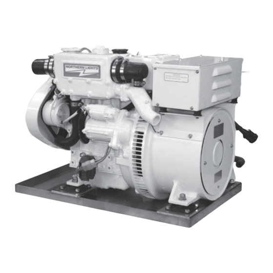
Page 4: Introduction
M - Northern Lights marine generator set Bore Cylinders 67 mm Northern Lights marine diesel generator set with a 673 engine, TF-276M generator end, M673M and an automatic voltage regulator. Northern Lights marine diesel generator set with a 673 engine, TF-276D generator end, M673L and an automatic voltage regulator. -
Page 5: Warranty
• Do not oil or grease engine while it is running. • Provide fi rst aid kits. CAUTION: This symbol is used throughout this book to alert you to possible danger areas. Please take special notice of these sections. OM673 09/09... -
Page 6: Component Locations M673 Marine Generator
13. Generator Control Box 20. Sea Water Pump 27. Fuel Inlet and Return 5. Wet Exhaust Elbow 14. AC Circuit Breaker 21. Lube Oil Fill- Side 28. AVR Circuit Breaker 6. Generator End Cover 7. Base and Drip Pan OM673 09/09... -
Page 7: Northern Lights Generator Sets
NOTE: Always leave this switch in the ON position while the unit is running. 10. A.C. AMMETER Shows the generator load on each phase. The phase is Figure 6-C: Series 4 Generator Control Panel selected with the Ammeter Selector switch (Item 9). OM673 09/09... - Page 8 Shows the generator output voltage. 12. A.C. AMMETER Shows the generator load on each phase. The phase is Figure 7-B: Status Indicators for Series 7.3 through selected with the Ammeter Selector switch ( Item 9 Series 7.6 Generator Control Panels. OM673 09/09...
-
Page 9: Operating Procedures
1. Remove electrical load from the generator set. 2. Run the engine for a 3 to 5 minute cool down period. 2. Move the Engine Control switch to the STOP posi- tion momentarily. 3. Marine Sets: shut off the seacock, fuel valve, and battery switch. OM673 09/09... -
Page 10: Shutdowns And Alarms
fi eld service. The parts are pressure. available from your local Northern Lights dealer. a. Generator sets have shutdown systems to stop the Some marine models already have “On-Board-Kits,”... -
Page 11: Servicing Schedule Chart
5) After fi rst 50 hours, and again after fi rst 100 hours, then every 2) Consult manufacturer's maintenance schedule, note on chart. 250 hours. 3) Whenever necessary. 6) Change air cleaner element at 1000 hours. 4) More often if necessary. OM673 09/09... - Page 12 Notes OM673 09/09...
-
Page 13: Lubrication - General
6. Fill engine with recommended oil. Start engine and check for leakage. Stop engine, wait 3 minutes, and check oil level. Add additional oil if necessary. 7. Oil fi lter part numbers are: 673M – #24-02001 673L – #24-08001 OM673 09/09... -
Page 14: Air Filter
7.2 - 8.7 ft/lbs (1.0 - 1.2 kg/m). 6. Re-install injectors and tubes and rocker cover. Torque injectors to: 43 - 51 ft/lbs (6 - 7 kg/m) Use new injector sealing washers. Figure 9: 673M Head Torque Sequence OM673 09/09... -
Page 15: Fuels - General
Keep dirt, scale, water, and other foreign matter #24-52020 out of fuel. b. Avoid storing fuel for long periods of time. c. Fill the fuel tank at the end of each day’s operation. This will reduce condensation. Found on all M673M, D, & L units OM673 09/09... -
Page 16: Bleeding The Fuel System
4. If the engine does not start after the above bleeding process, loosen a fuel line at the injector. Crank the engine until fuel escapes, then tighten the connec- tion. Do each line one at a time. 5. After the engine has started, check for fuel leaks. OM673 09/09... -
Page 17: Injector Service
1. Injectors should be checked every 600 hours. Check 1. Since operating conditions may vary considerably, it should be made by a Northern Lights dealer or local is diffi cult to give a defi nite interval for checking the injection repair station. -
Page 18: Injection Pump
Figure 13: Remove delivery lines. Figure 17: Unscrew injector. Figure 14: Cover lines, inlets and injection pump outlets. Figure 18: Remove and replace copper sealing washer. Figure 15: Remove return line nuts. Figure 19: Reinstall injector. Torque to proper tightness. OM673 09/09... -
Page 19: Cooling System Flushing
It is located in the side of the a metal rod. Flush, inspect and clean again if neces- generator junction box. sary. 5. Reassemble. Fill the cooling system, start the engine and check for leaks. OM673 09/09... -
Page 20: Glow Plugs
(+) terminal of main battery. Then, connect negative (-) terminal of booster battery to ground on the engine block ( see Figure 21 4. Remove booster battery after starting engine. 5. Sealed batteries: See manufacturer charging and booster instructions. Figure 21: Battery connections. OM673 09/09... -
Page 21: Electrical System - General
11. Shaft 12. Ventilation Cover CONTROL BOX (Figure 24) Control Terminal Board Automatic Voltage Regulator (AVR) 12 Volt DC Circuit Breaker AC Circuit Breaker AVR Circuit Breaker Output Terminal Board Figure 23: Generator Components. Figure 24: Control Box Components. OM673 09/09... -
Page 22: Connections
240 Figure 27 Figure 27: Control Terminal Board, 240 Volt Output b. Connect U2 to V1 on the output terminal board Figure 30: Output Terminal Board, 120/240 Volt Output Figure 28 OM673 09/09... -
Page 23: Operation
Dust and foreign material may reduce the fl ow of d. Generator bearing should be replaced by your cooling air, reducing heat dissipation and causing Northern Lights dealer at 10,000 hours. the generator to overheat. 6. Check the brushes b. - Page 24 8. Generator Protection To protect the generator and AVR from unbalanced loads and over loads, two 20 amp breakers are placed in the output circuit and one 3 amp breaker is placed in the AVR sensing circuit ( Figure 34 OM673 09/09...
-
Page 25: Troubleshooting
• Clean and tighten battery and harness plug connections. Sulfated or worn out batteries • Check specifi c gravity and electrolyte level of each battery. Dead Battery • Charge battery. If you cannot correct problems with these procedures, see your Northern Lights dealer. OM673 09/09... -
Page 26: Engine
• See “Engine Overheats” in next category. Below normal engine temperature • Remove and check thermostat. Improper valve clearance • Reset valves. Best done by dealer. Dirty or faulty injection nozzles • Replace injectors. Best done by dealer. • See your local dealer. OM673 09/09... - Page 27 • Fill crankcase to proper level. Improper type of oil • Drain and fi ll crankcase with correct oil. Partially plugged oil fi lter • Replace fi lter. If you cannot correct problems with these procedures, see your Northern Lights dealer. OM673 09/09...
-
Page 28: Engine
Cold engine • Warm up engine to normal operating temperature. Defective thermostat • Remove and check thermostat. Engine out of time • See your dealer. If you cannot correct problems with these procedures, see your Northern Lights dealer. OM673 09/09... -
Page 29: Data Sheets Marine
Northern Lights Marine Data M673D M673M M673L Model: 1800 1500 1800 1500 1800 1500 kW Rating Frequency (Hz) GENERAL INFORMATION Cylinders Displacement 41.1 in 41.1 in 41.1 in 41.1 in 46.4 in 46.4 in (0.676 ltr) (0.676 ltr) (0.676 ltr) (0.676 ltr) -
Page 30: Marine
Northern Lights Marine Data M673D M673M M673L Model: 1800 1500 1800 1500 1800 1500 kW Rating Frequency (Hz) ELECTRICAL Minimum Battery Capacity (Amp/hr) Battery Cable Size #1 up to 10 ft #1 up to 10 ft #1 up to 10 ft... - Page 31 DC Wiring Diagrams OM673 09/09...
-
Page 32: Wiring Diagrams
AC Wiring Diagrams AC Wiring Diagram Drawing #B-6103G Wiring diagrams are subject to change without notice. OM673 09/09... - Page 33 AC Wiring Diagrams AC Wiring Diagram Drawing #B-6104E Wiring diagrams are subject to change without notice. OM673 09/09...
- Page 34 AC Wiring Diagrams AC Wiring Diagram Drawing #B-6105D Wiring diagrams are subject to change without notice. OM673 09/09...
- Page 35 4420 14th Ave. NW., Seattle WA 98107 Tel: (206) 789-3880 • 1-800-762-0165 • Fax: (206) 782-5455 Northern Lights and Lugger are registered trademarks of Northern Lights, Inc. www.northern-lights.com © 2009 All rights reserved. Litho USA.
Need help?
Do you have a question about the Lugger OM673 and is the answer not in the manual?
Questions and answers